Use of the Seeed Studio Round Display extension
This tutorial will explain in detail how to use the extended functions on the Round Display, including the use of the RTC function, SD card function, and screen function.
Getting Started
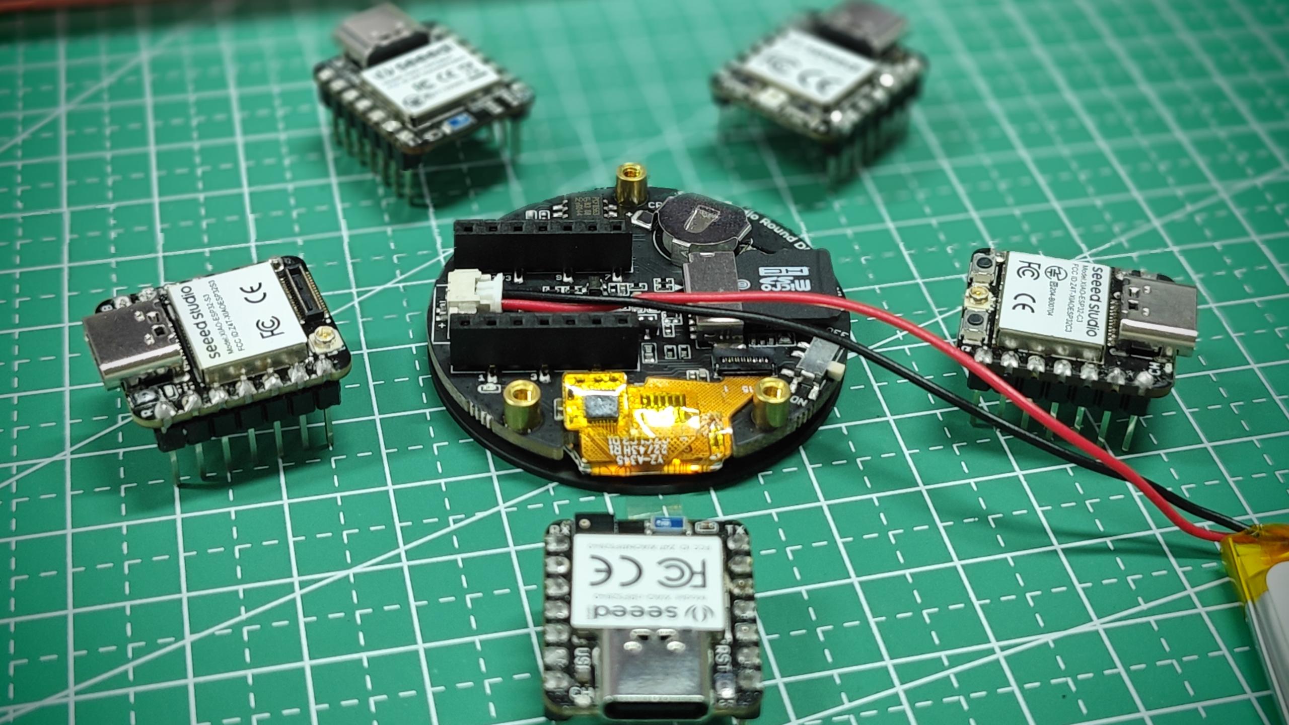
The content of this tutorial supports all XIAO series products. So you can use any XIAO to complete the content of this Wiki.
If you are using Round Display for the first time, you may want to read the prep content we wrote for it earlier and configure the library's environment according to this content to make sure you can use Round Display smoothly.
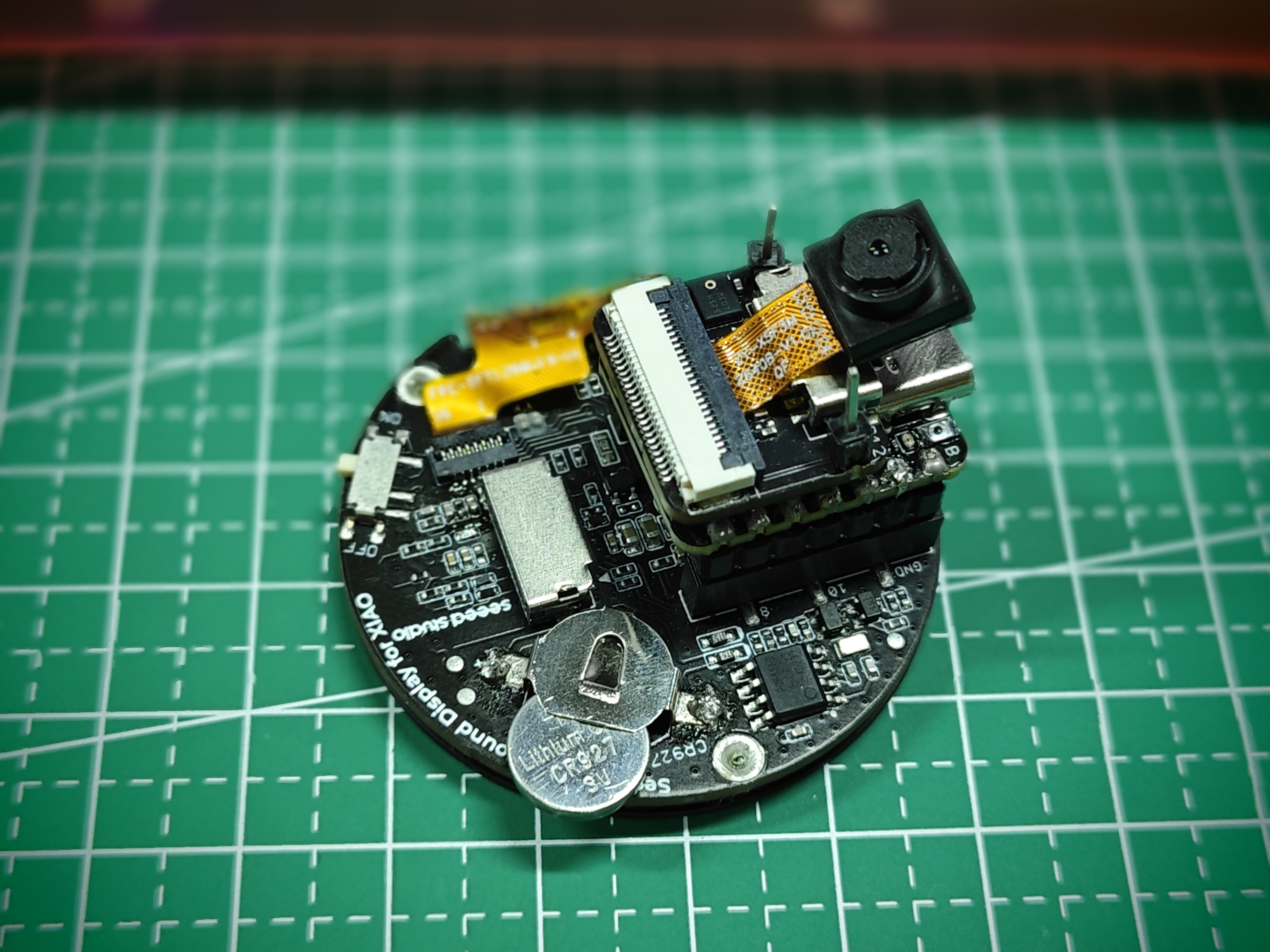
Install a microSD card
Round Display supports the use of microSD cards with FAT32 format no larger than 32GB. When installing a microSD card, the gold finger of the microSD card should be inserted towards the inside of the board.
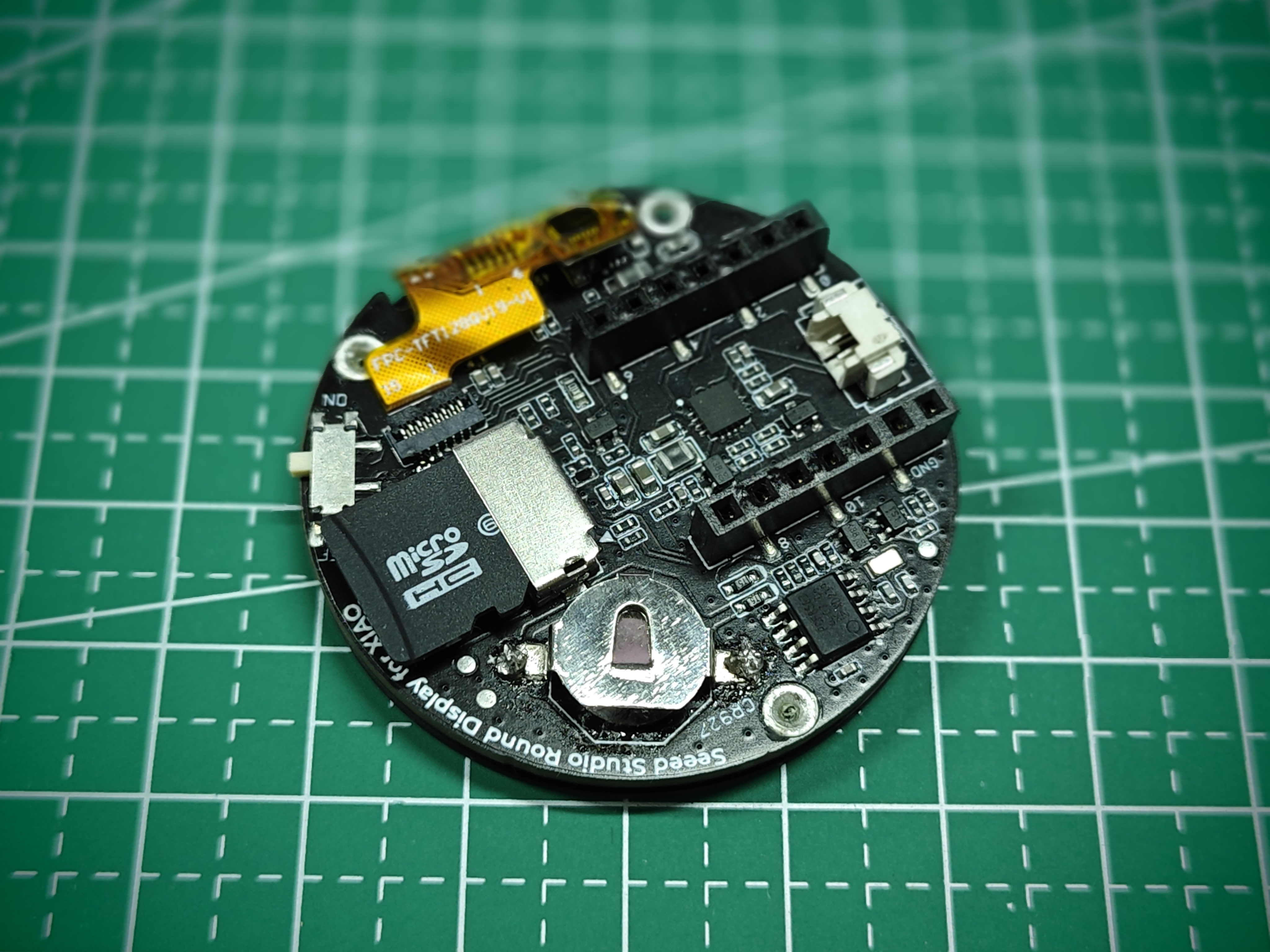
Install the RTC battery
Round Display supports RTC function, and it has a built-in PCF8563T chip. If you need to use the RTC function, you may need a coin cell battery to keep the RTC working.
We recommend using CR927 series button cell batteries with the positive (flat) terminal facing outward and the negative (slightly protruding surface) facing inward when installed.
The above picture only shows the battery installation direction, not fully installed battery. The correct installation of the battery should be fully inserted into the battery holder.
Install power supply battery
Round Display supports external 3.7V lithium battery. And with a built-in power management chip, the battery can be charged through XIAO's USB port.
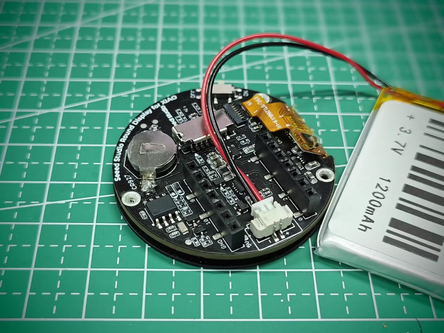
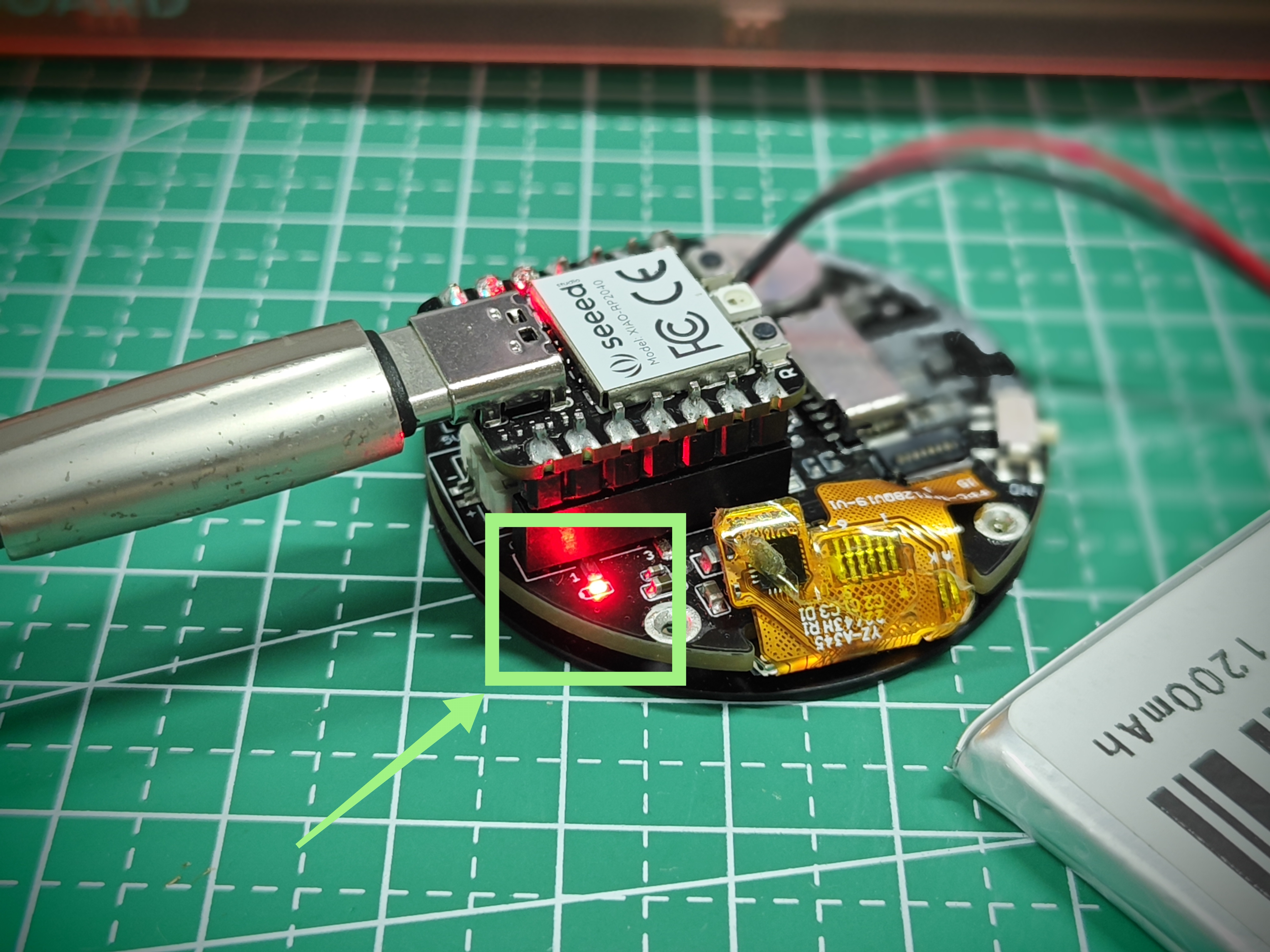
The Round Display also has a charging indicator. It has three states:
- The indicator light is always on at low brightness when the lithium battery is not connected.
- Connect the lithium battery and the red light is always on at high brightness when charging the lithium battery.
- Lithium battery is connected and the light goes off when the battery is fully charged.
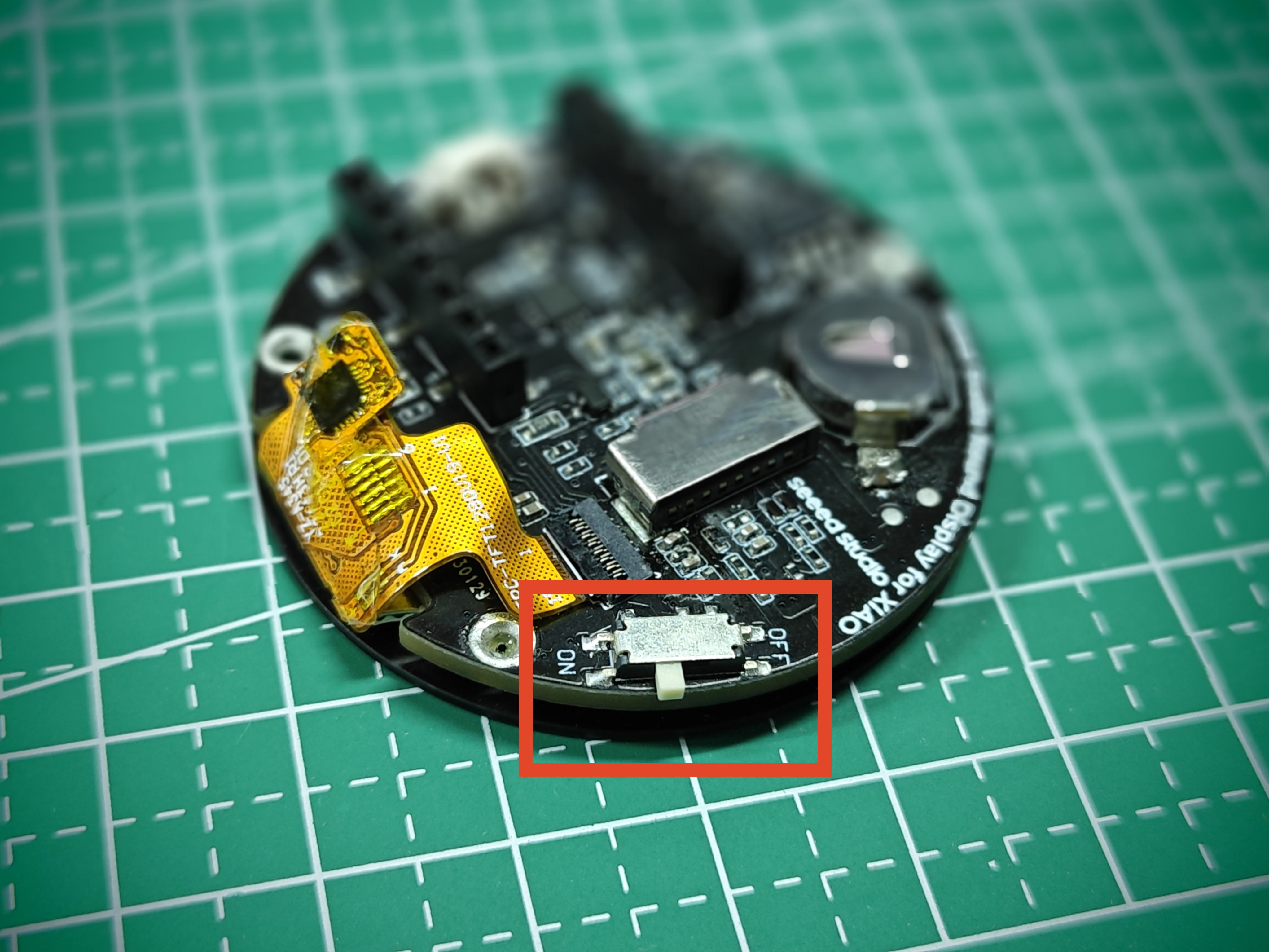
Round Display switch
There is also a switch on the Round Display. The switch is used to control the on/off of the display and the power supply to the XIAO. When you flip the switch to OFF, the battery will not power the XIAO and the display screen will turn off. When you turn the switch to ON, the display will light up and the battery will power the XIAO (provided that a power supply battery is installed) to ensure that the program runs.
Powering the XIAO in the description here refers to powering the XIAO through the Round Display. If you are powering the XIAO directly, then the switch on the Round Display cannot disconnect the power to the XIAO. If you want to control the whole device through the switch on the Round Display, you need to install the power supply battery on the Round Display.
Also note that some XIAOs (such as the XIAO ESP32C3) may require a press of the Reset button on the XIAO to start working when powering down and powering up again to run a program.
Round Display circuit design
In this section, we will intercept the circuit schematic of the hardware of Round Display and inform users which IO pins on XIAO are used in the hardware of Round Display to avoid conflicts in the use of IO.
Measure battery voltage pins
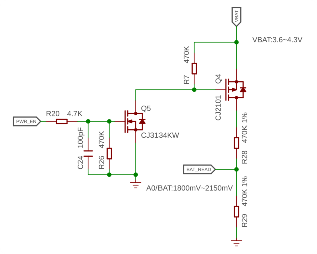
For the design of the Round Display, we used the A0/D0 pins on the XIAO to connect to the circuitry of the on-board battery. The remaining battery charge can be obtained by reading the analog value of this pin.
SD card circuit pins
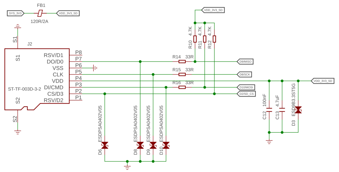
The SD card section uses the four IO ports on the XIAO, which are used as shown in the table below.
| XIAO GPIO | microSD Card Slot |
|---|---|
| D2 | CS |
| D8 | SCK |
| D9 | MISO |
| D10 | MOSI |
RTC circuit pins
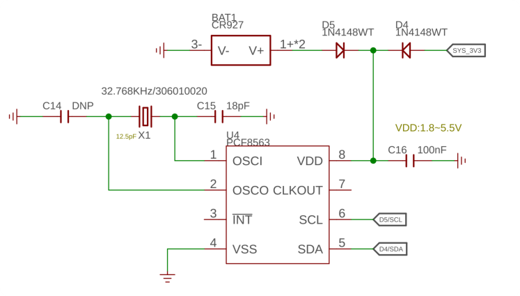
The RTC function uses the IIC protocol, so it occupies the D5 (SCL) and D4 (SDA) pins.
Touch screen circuit pins
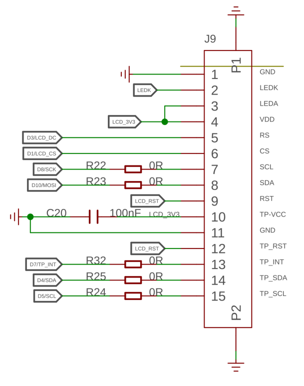
The touch screen section uses the four IO ports on the XIAO, which are used as shown in the table below.
| XIAO GPIO | Touch screen |
|---|---|
| D4 (SDA) | Touch Screen IIC |
| D5 (SCL) | Touch Screen IIC |
| D3 | LCD_DC |
| D1 | LCD_CS |
| D7 | TP_INT |
| D6 | Screen backlight |
Round Display library Overview
The vast majority of Round Display's software development is based on XIAO's own hardware support. The graphics are based on the TFT library, the LVGL library, and the Arduino GFX library.
In order to facilitate users to use the functions on Round Display, we wrote a separate library that mainly calls the interfaces of the above libraries to reduce the threshold of independent development by the users themselves when they arrive at a later stage. In this chapter, we will focus on what are the functions of these libraries that I prepared for Round Display and how to use them respectively.
lv_xiao_round_screen.h
The lv_xiao_round_screen.h file is a header file in the Round Display library, which drives the display and touch functions of the screen.
A macro definition check is made at the beginning of the file and is intended to require that developers using Round Display need to select the graphics library you want to develop when drawing screen patterns. There are two choices, TFT and Arduino GFX. if you choose the TFT library, then it is the one that can support LVGL.
#if defined(USE_TFT_ESPI_LIBRARY) && defined(USE_ARDUINO_GFX_LIBRARY)
#error "More than one graphics library is defined."
#elif defined(USE_TFT_ESPI_LIBRARY)
#include <TFT_eSPI.h>
TFT_eSPI tft = TFT_eSPI(SCREEN_WIDTH, SCREEN_HEIGHT);
#elif defined(USE_ARDUINO_GFX_LIBRARY)
#include <Arduino_GFX_Library.h>
The reason for this design is that certain XIAO has its own advantages in drawing patterns on different graphic libraries. For example if you are using the XIAO nRF52840, then you may be more memory efficient and stable using the Arduino GFX library. For XIAO ESP32S3, a large memory XIAO has an inherent advantage in handling graphics libraries like LVGL, and is also able to draw more complex patterns and UI.
So if you need to draw a pattern using Round Display, don't forget to select the graphics library you want to use and define it at the beginning of your Arduino program.
- If you want to use the TFT library or the LVGL library:
#define USE_TFT_ESPI_LIBRARY
- If you want to use the Arduino GFX library:
#define USE_ARDUINO_GFX_LIBRARY
-
void xiao_disp_init(void): This function is used to initialize the display backlight and rotate the display to its initial position, with the device display backplane color being solid black. This function is generally not used alone, and thelv_xiao_disp_init()function is used instead when initialization is needed. -
void lv_xiao_disp_init(void): Initialize the backlight, and initialize the display driver. Typically used for display initialization. -
bool chsc6x_is_pressed(void): This function is used to check if the screen is touched, and returnsTureif the screen is touched. -
void lv_xiao_touch_init(void): This function is used to initialize the touch screen and its driver. -
void chsc6x_read( lv_indev_drv_t * indev_driver, lv_indev_data_t * data ): This function is used to get the coordinate points of the touch screen.
lv_hardware_test.h
The lv_hardware_test.h file is the header file in the sample HardwareTest in the Round Display library. This header file prepares most of the hardware usage functions for Round Display.
If you want to use the functions inside this header file, you can copy the file directly to the same file directory of your Arduino file.
-
int32_t battery_level_percent(void): By calling this function, you can read and calculate the battery charge percentage to display the battery level in the application. -
void lv_hardware_test(void): This function is used to test all hardware functions, including screen display, screen touch, RTC clock and battery level. You can refer to this function writing method to complete the development of the Round Display function you want.
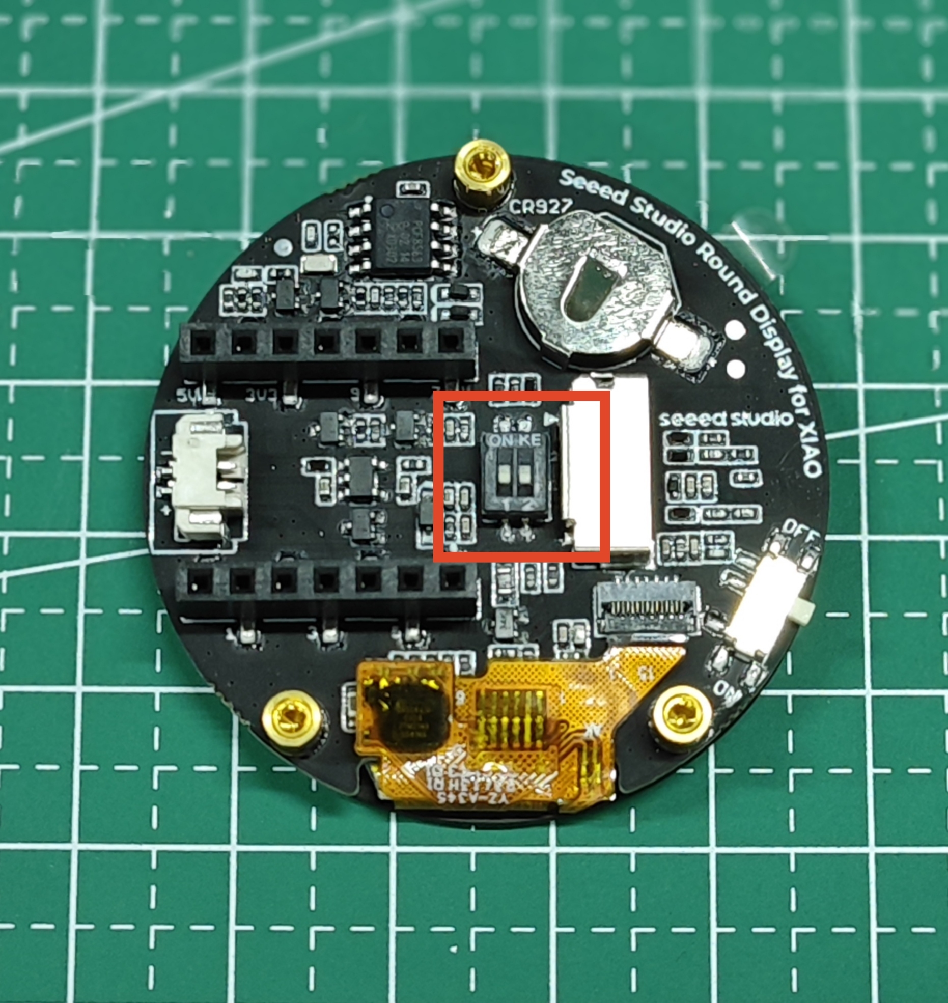
KE Button & GPIO
On the new version of the Round Display, we have designed a KE switch to selectively release certain GPIOs for selective use by the user.
The KE switch is designed in the middle of the microSD card slot and the row of pins that connect to the XIAO.
The circuit design for this switch is shown below.
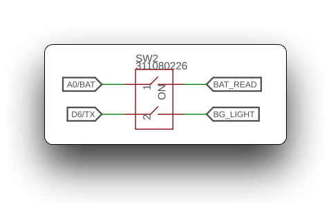
This means that when the switch is closed (toggled to the ON side) then the Round Display's battery voltage reading function and display backlight function become available.
When the switch is disconnected (toggled to the digital side), then pins A0 and D6 on the XIAO are the available states.
Measure battery voltage
Due to the lack of IO pins on the XIAO, the majority of XIAOs are unable to measure battery voltage, although the power management chip is configured on some XIAOs to allow external batteries.
But if you choose to use Round Dislay and power the XIAO through the screen, then measuring the battery voltage will become a reality.
The following is a sample program to measure the battery voltage. The function battery_level_percent() is selected from the lv_hardware_test.h file.
#define NUM_ADC_SAMPLE 20 // Sampling frequency
#define RP2040_VREF 3300 // When you use the XIAO RP2040, you need to measure the actual voltage at the 3.3V pin and modify that value. (unit: mV)
#define BATTERY_DEFICIT_VOL 1850 // Battery voltage value at loss of charge
#define BATTERY_FULL_VOL 2450 // Battery voltage value at full charge
int32_t battery_level_percent(void)
{
int32_t mvolts = 0;
#if defined(CONFIG_IDF_TARGET_ESP32S3) || defined(CONFIG_IDF_TARGET_ESP32C3)
for(int8_t i=0; i<NUM_ADC_SAMPLE; i++){
mvolts += analogReadMilliVolts(D0);
}
mvolts /= NUM_ADC_SAMPLE;
#elif defined(ARDUINO_SEEED_XIAO_NRF52840_SENSE) || defined(ARDUINO_SEEED_XIAO_NRF52840)
analogReference(AR_INTERNAL2V4); // 0.6V ref 1/4 Gain
int32_t adc_raw = 0;
for(int8_t i=0; i<NUM_ADC_SAMPLE; i++){
adc_raw += analogRead(D0);
}
adc_raw /= NUM_ADC_SAMPLE;
mvolts = 2400 * adc_raw / (1<<12);
#elif defined(ARDUINO_SEEED_XIAO_RP2040)
int32_t adc_raw = 0;
for(int8_t i=0; i<NUM_ADC_SAMPLE; i++){
adc_raw += analogRead(D0);
}
adc_raw /= NUM_ADC_SAMPLE;
mvolts = RP2040_VREF * adc_raw / (1<<12);
#endif
int32_t level = (mvolts - BATTERY_DEFICIT_VOL) * 100 / (BATTERY_FULL_VOL-BATTERY_DEFICIT_VOL); // 1850 ~ 2100
level = (level<0) ? 0 : ((level>100) ? 100 : level);
return level;
}
void setup() {
// put your setup code here, to run once:
Serial.begin(115200);
while(!Serial);
analogReadResolution(12);
}
void loop() {
// put your main code here, to run repeatedly:
int32_t batteryVal = battery_level_percent();
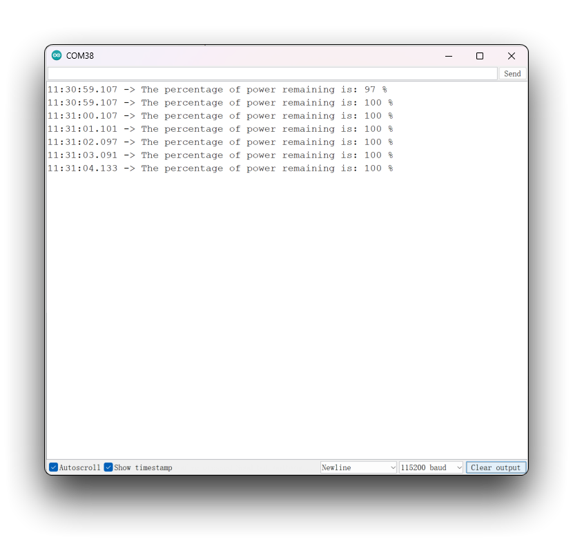
Serial.print("The percentage of power remaining is: ");
Serial.print(batteryVal);
Serial.print(" %");
Serial.println();
delay(1000);
}
This program is not a universal program, and the measured battery percentage may not be accurate. This is because everyone uses different batteries and chips and development boards, so you may need to modify the program according to the actual situation when executing this program. Please refer to the program annotation section of this section for the method of modification.
Select the XIAO board you are using, upload the program, open the serial monitor, and set the baud rate to 115200. If you have the battery connected and powered on, you should be able to see the battery voltage in the serial monitor.
Program annotation
This code uses an ADC to measure the battery voltage and calculate the battery level percentage. The implementation varies depending on the hardware platform:
- For ESP32-S3 and ESP32-C3 platforms, the
analogReadMilliVoltsfunction is used to read the analog voltage values, and then the average value of multiple samples is taken to obtain the average battery voltage. - For Seeeduino XIAO NRF52840 platforms, the
analogReferencefunction is first used to specify the reference voltage as 2.4V, and then the analogRead function is used to read the analog voltage values, and the average battery voltage is calculated. - For the Seeeduino XIAO RP2040 platform, the
analogReadfunction is used to read the analog voltage values, and the average battery voltage is calculated.
In any case, the average battery voltage is calculated, and then the battery level percentage is calculated using the formula (mvolts - BATTERY_DEFICIT_VOL) * 100 / (BATTERY_FULL_VOL - BATTERY_DEFICIT_VOL), where mvolts is the average battery voltage, BATTERY_DEFICIT_VOL is the minimum operating voltage of the battery, and BATTERY_FULL_VOL is the maximum voltage of the battery. Finally, the code limits the battery level percentage to ensure that it is between 0 and 100.
In summary, the following parameters determine the accuracy of the voltage measurement when using this program.
#define RP2040_VREF 3300            // When you use the XIAO RP2040, you need to measure the actual voltage at the 3.3V pin and modify that value. (unit: mV)
#define BATTERY_DEFICIT_VOL 1850    // Battery voltage value at loss of charge
#define BATTERY_FULL_VOL 2450       // Battery voltage value at full charge
The first thing you need to do is to get the analog value of the battery you purchased when it is at a loss of charge/full charge.
You can get the analog value of the battery by using this function. You need to get the value once in both full and deficit battery states.
int32_t battery_test(void)
{
  int32_t mvolts = 0;
#if defined(CONFIG_IDF_TARGET_ESP32S3) || defined(CONFIG_IDF_TARGET_ESP32C3)
  for(int8_t i=0; i<NUM_ADC_SAMPLE; i++){
    mvolts += analogReadMilliVolts(D0);
  }
  mvolts /= NUM_ADC_SAMPLE;
#elif defined(ARDUINO_SEEED_XIAO_NRF52840_SENSE) || defined(ARDUINO_SEEED_XIAO_NRF52840)
  analogReference(AR_INTERNAL2V4);  // 0.6V ref  1/4 Gain
  int32_t adc_raw = 0;
  for(int8_t i=0; i<NUM_ADC_SAMPLE; i++){
    adc_raw += analogRead(D0);
  }
  adc_raw /= NUM_ADC_SAMPLE;
  mvolts = 2400 * adc_raw / (1<<12);
#elif defined(ARDUINO_SEEED_XIAO_RP2040)
  int32_t adc_raw = 0;
  for(int8_t i=0; i<NUM_ADC_SAMPLE; i++){
    adc_raw += analogRead(D0);
  }
  adc_raw /= NUM_ADC_SAMPLE;
  mvolts = RP2040_VREF * adc_raw / (1<<12);
#endif
  return mvolts;
}
The battery_test() function is actually the battery_level_percent() function with the last two lines of code to calculate the percentage removed.
Then just modify the value of the program corresponding to the value you measured.
If you are using the XIAO RP2040, then one additional step you will need to do is to use a voltmeter to measure the actual voltage on the 3.3V pin of the XIAO RP2040. The measured voltage value is converted into mV units, and the corresponding program is modified.
For example, here are the actual measurements I took using my XIAO RP2040 and battery.
#define RP2040_VREF 3080
#define BATTERY_DEFICIT_VOL 1541
#define BATTERY_FULL_VOL 1791
RTC function
RTC function part, we mainly divided into the following four sections to introduce its application.
- First is for XIAO without network function, you can correct the RTC by manually setting the initial time.
- Then power the RTC with the help of coin cell battery to get the accurate time continuously.
- For XIAO with network function, you can use the network function to correct the time.
- Draw a simple clock dial by combining the RTC function.
Off-line manual calibration of the RTC
The following is a sample program to manually calibrate the RTC time. The settings are placed in the Setup() function to ensure that the setup program is executed only once. This procedure is the most efficient way to set the initial RTC time for XIAO without network capability.
#include "I2C_BM8563.h"

I2C_BM8563 rtc(I2C_BM8563_DEFAULT_ADDRESS, Wire);

void setup() {
  // Init Serial
  Serial.begin(115200);
  while(!Serial);
  delay(50);

  // Init I2C
  Wire.begin();

  // Init RTC
  rtc.begin();

  // Set RTC Date
  I2C_BM8563_DateTypeDef dateStruct;
  dateStruct.weekDay = 3;
  dateStruct.month = 4;
  dateStruct.date = 26;
  dateStruct.year = 2023;
  rtc.setDate(&dateStruct);

  // Set RTC Time
  I2C_BM8563_TimeTypeDef timeStruct;
  timeStruct.hours   = 9;
  timeStruct.minutes = 43;
  timeStruct.seconds = 10;
  rtc.setTime(&timeStruct);

  Serial.println("RTC time calibration complete!");
}

void loop() {

}
After uploading the program and turning on the serial monitor, the RTC time will start to calibrate. When RTC time calibration complete! appears, calibration is complete.
Get RTC time
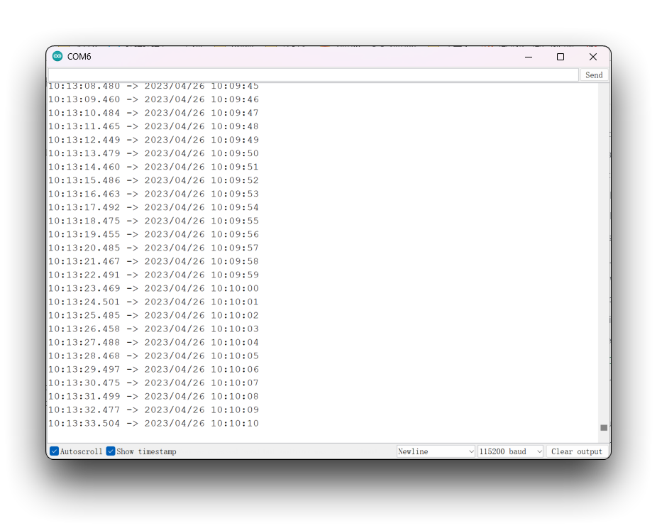
The following program gets the time of the RTC every second and prints it out in the serial monitor.
The procedure to obtain the RTC time can be used after the manual calibration procedure above. The time calibration procedure needs to be performed only once and the RTC clock will be able to work continuously under the power of the coin cell battery, after which you only need to use the procedure for obtaining the time to get the exact time.
We do not recommend to use the program to calibrate the time and get the time together, so that when the XIAO is powered up, both will reset once according to the time you configured, then you will never get the accurate time.
#include "I2C_BM8563.h"

I2C_BM8563 rtc(I2C_BM8563_DEFAULT_ADDRESS, Wire);

void setup() {
  // Init Serial
  Serial.begin(115200);
  delay(50);

  // Init I2C
  Wire.begin();

  // Init RTC
  rtc.begin();
}

void loop() {
  I2C_BM8563_DateTypeDef dateStruct;
  I2C_BM8563_TimeTypeDef timeStruct;

  // Get RTC
  rtc.getDate(&dateStruct);
  rtc.getTime(&timeStruct);

  // Print RTC
#if defined(CONFIG_IDF_TARGET_ESP32S3) || defined(CONFIG_IDF_TARGET_ESP32C3)
  Serial.printf("%04d/%02d/%02d %02d:%02d:%02d\n",
              dateStruct.year,
              dateStruct.month,
              dateStruct.date,
              timeStruct.hours,
              timeStruct.minutes,
              timeStruct.seconds
              );
#else
  Serial.print(dateStruct.year);
  Serial.print(", ");
  Serial.print(dateStruct.month);
  Serial.print(", ");
  Serial.print(dateStruct.date);
  Serial.print(", ");
  Serial.print(timeStruct.hours);
  Serial.print(", ");
  Serial.print(timeStruct.minutes);
  Serial.print(", ");
  Serial.print(timeStruct.seconds);
  Serial.println();
#endif

  // Wait
  delay(1000);
}
Network calibration RTC time
For XIAO, which has network capabilities, things seem to get a lot easier. With a network, you don't even need to use a coin cell battery to keep the RTC working out of the box, you just need to network the timing every time you power it up.
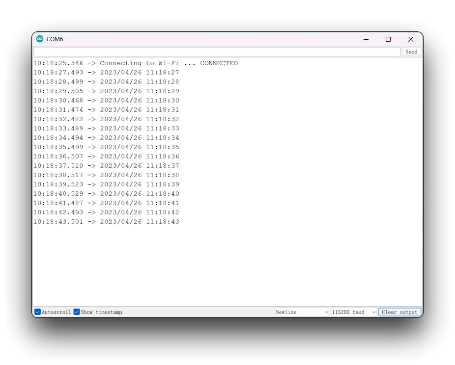
The following is a sample program for network timing and outputting the RTC time reading on the serial monitor.
This program is only applicable to XIAO ESP32 series. Because only this series has network function.
#include "I2C_BM8563.h"
#include <WiFi.h>

I2C_BM8563 rtc(I2C_BM8563_DEFAULT_ADDRESS, Wire);

const char* ntpServer = "time.cloudflare.com";
const char *ssid     = "YOUR_SSID";
const char *password = "YOUR_PASSWORD";

void setup() {
  // Init Serial
  Serial.begin(115200);
  delay(50);

  // Connect to an access point
  WiFi.begin(ssid, password);
  Serial.print("Connecting to Wi-Fi ");
  while (WiFi.status() != WL_CONNECTED) {
    delay(500);
    Serial.print(".");
  }
  Serial.println(" CONNECTED");

  // Set ntp time to local
  configTime(9 * 3600, 0, ntpServer);

  // Init I2C
  Wire.begin();

  // Init RTC
  rtc.begin();

  // Get local time
  struct tm timeInfo;
  if (getLocalTime(&timeInfo)) {
    // Set RTC time
    I2C_BM8563_TimeTypeDef timeStruct;
    timeStruct.hours   = timeInfo.tm_hour;
    timeStruct.minutes = timeInfo.tm_min;
    timeStruct.seconds = timeInfo.tm_sec;
    rtc.setTime(&timeStruct);

    // Set RTC Date
    I2C_BM8563_DateTypeDef dateStruct;
    dateStruct.weekDay = timeInfo.tm_wday;
    dateStruct.month   = timeInfo.tm_mon + 1;
    dateStruct.date    = timeInfo.tm_mday;
    dateStruct.year    = timeInfo.tm_year + 1900;
    rtc.setDate(&dateStruct);
  }
}

void loop() {
  I2C_BM8563_DateTypeDef dateStruct;
  I2C_BM8563_TimeTypeDef timeStruct;

  // Get RTC
  rtc.getDate(&dateStruct);
  rtc.getTime(&timeStruct);

  // Print RTC
#if defined(CONFIG_IDF_TARGET_ESP32S3) || defined(CONFIG_IDF_TARGET_ESP32C3)
    Serial.printf("%04d/%02d/%02d %02d:%02d:%02d\n",
                dateStruct.year,
                dateStruct.month,
                dateStruct.date,
                timeStruct.hours,
                timeStruct.minutes,
                timeStruct.seconds
               );
#else
     Serial.print(dateStruct.year);
     Serial.print(", ");
     Serial.print(dateStruct.month);
     Serial.print(", ");
     Serial.print(dateStruct.date);
     Serial.print(", ");
     Serial.print(timeStruct.hours);
     Serial.print(", ");
     Serial.print(timeStruct.minutes);
     Serial.print(", ");
     Serial.print(timeStruct.seconds);
     Serial.println();
#endif

  // Wait
  delay(1000);
}
When you use this program, please fill in the name and password of the network according to your actual situation. After uploading the program, open the serial monitor and set the baud rate to 115200, then you can see the exact time.
Simple dial based on RTC time
The following program is a dial program based on RTC clock drawing.
The following program is only compatible with XIAO except for XIAO nRF52840. XIAO nRF52840 currently has problems with TFT compatibility. But you may consider using the Arduino GFX library or LVGL to draw the dials.
#include <Arduino.h>
#include <TFT_eSPI.h>
#include <SPI.h>
#include "I2C_BM8563.h"
#include <Wire.h>

#define USE_TFT_ESPI_LIBRARY

#include "lv_xiao_round_screen.h"

I2C_BM8563 rtc(I2C_BM8563_DEFAULT_ADDRESS, Wire);

#if defined(CONFIG_IDF_TARGET_ESP32S3) || defined(CONFIG_IDF_TARGET_ESP32C3)
#include "esp_wifi.h"
#include "WiFi.h"

  const char *ntpServer = "time.cloudflare.com";
  const char *ssid     = "YOUR_SSID";
  const char *password = "YOUR_PASSWORD";
#elif defined(ARDUINO_SEEED_XIAO_NRF52840_SENSE) || defined(ARDUINO_SEEED_XIAO_NRF52840)
#error "This procedure is not applicable to XIAO nRF52840 series, please replace other XIAO and try again."
#endif


//TFT_eSPI tft = TFT_eSPI();  // Invoke library, pins defined in User_Setup.h
TFT_eSprite face = TFT_eSprite(&tft);

#define CLOCK_X_POS 0
#define CLOCK_Y_POS 0

#define CLOCK_FG   TFT_SKYBLUE
#define CLOCK_BG   TFT_NAVY
#define SECCOND_FG TFT_RED
#define LABEL_FG   TFT_GOLD

#define CLOCK_R       240.0f / 2.0f // Clock face radius (float type)
#define H_HAND_LENGTH CLOCK_R/2.0f
#define M_HAND_LENGTH CLOCK_R/1.4f
#define S_HAND_LENGTH CLOCK_R/1.3f

// Calculate 1 second increment angles. Hours and minute hand angles
// change every second so we see smooth sub-pixel movement
#define SECOND_ANGLE 360.0 / 60.0
#define MINUTE_ANGLE SECOND_ANGLE / 60.0
#define HOUR_ANGLE   MINUTE_ANGLE / 12.0

// Sprite width and height
#define FACE_W CLOCK_R * 2 + 1
#define FACE_H CLOCK_R * 2 + 1

// Time h:m:s
uint8_t h = 0, m = 0, s = 0;

float time_secs = h * 3600 + m * 60 + s;

// Time for next tick
uint32_t targetTime = 0;

// =========================================================================
// Setup
// =========================================================================
void setup() {
  Serial.begin(115200);
  Serial.println("Booting...");

  // Initialise the screen
  tft.init();

  // Ideally set orientation for good viewing angle range because
  // the anti-aliasing effectiveness varies with screen viewing angle
  // Usually this is when screen ribbon connector is at the bottom
  tft.setRotation(0);
  tft.fillScreen(TFT_BLACK);

  // Create the clock face sprite
  //face.setColorDepth(8); // 8 bit will work, but reduces effectiveness of anti-aliasing
  face.createSprite(FACE_W, FACE_H);

  // Draw the whole clock - NTP time not available yet
  renderFace(time_secs);

#if defined(CONFIG_IDF_TARGET_ESP32S3) || defined(CONFIG_IDF_TARGET_ESP32C3)
  WiFi.begin(ssid, password);
  while ( WiFi.status() != WL_CONNECTED )
  {
    delay ( 500 );
    Serial.print ( "." );
  }
  configTime(8 * 3600, 0, ntpServer);
#endif

  Wire.begin();
  rtc.begin();

//  struct tm timeInfo;
  I2C_BM8563_TimeTypeDef timeStruct;
  I2C_BM8563_DateTypeDef dateStruct;

// In case of XIAO ESP32 series, use network timing.
#if defined(CONFIG_IDF_TARGET_ESP32S3) || defined(CONFIG_IDF_TARGET_ESP32C3)
  struct tm timeInfo;
  if (getLocalTime(&timeInfo)) {
    timeStruct.hours   = timeInfo.tm_hour;
    timeStruct.minutes = timeInfo.tm_min;
    timeStruct.seconds = timeInfo.tm_sec;
    rtc.setTime(&timeStruct);
  }
#else
  // Set RTC time, Other XIAOs do not have network functions and require manual time alignment.
  // Please note that the setting time should be set only once.
  timeStruct.hours   = 9;
  timeStruct.minutes = 43;
  timeStruct.seconds = 10;
  rtc.setTime(&timeStruct);
#endif

  targetTime = millis() + 100;
  rtc.getTime(&timeStruct);
  time_secs = timeStruct.hours * 3600 + timeStruct.minutes * 60 + timeStruct.seconds;
}

// =========================================================================
// Loop
// =========================================================================
void loop() {
  // Update time periodically
  if (targetTime < millis()) {

    // Update next tick time in 100 milliseconds for smooth movement
    targetTime = millis() + 100;

    // Increment time by 100 milliseconds
    time_secs += 0.100;

    // Midnight roll-over
    if (time_secs >= (60 * 60 * 24)) time_secs = 0;

    // All graphics are drawn in sprite to stop flicker
    renderFace(time_secs);

    I2C_BM8563_DateTypeDef dateStruct;
    I2C_BM8563_TimeTypeDef timeStruct;

    // Get RTC
    rtc.getTime(&timeStruct);

    // Print RTC
#if defined(CONFIG_IDF_TARGET_ESP32S3) || defined(CONFIG_IDF_TARGET_ESP32C3)
    Serial.printf("%02d:%02d:%02d\n",
                timeStruct.hours,
                timeStruct.minutes,
                timeStruct.seconds
               );
#else
     Serial.print(timeStruct.hours);
     Serial.print(", ");
     Serial.print(timeStruct.minutes);
     Serial.print(", ");
     Serial.print(timeStruct.seconds);
     Serial.println();
#endif
  }
}

// =========================================================================
// Draw the clock face in the sprite
// =========================================================================
static void renderFace(float t) {
  float h_angle = t * HOUR_ANGLE;
  float m_angle = t * MINUTE_ANGLE;
  float s_angle = t * SECOND_ANGLE;

  // The face is completely redrawn - this can be done quickly
  face.fillSprite(TFT_BLACK);

  // Draw the face circle
  face.fillSmoothCircle( CLOCK_R, CLOCK_R, CLOCK_R, CLOCK_BG );

  // Set text datum to middle centre and the colour
  face.setTextDatum(MC_DATUM);

  // The background colour will be read during the character rendering
  face.setTextColor(CLOCK_FG, CLOCK_BG);

  // Text offset adjustment
  constexpr uint32_t dialOffset = CLOCK_R - 10;

  float xp = 0.0, yp = 0.0; // Use float pixel position for smooth AA motion

  // Draw digits around clock perimeter
  for (uint32_t h = 1; h <= 12; h++) {
    getCoord(CLOCK_R, CLOCK_R, &xp, &yp, dialOffset, h * 360.0 / 12);
    face.drawNumber(h, xp, 2 + yp);
  }

  // Add text (could be digital time...)
  face.setTextColor(LABEL_FG, CLOCK_BG);
  face.drawString("TFT_eSPI", CLOCK_R, CLOCK_R * 0.75);

  // Draw minute hand
  getCoord(CLOCK_R, CLOCK_R, &xp, &yp, M_HAND_LENGTH, m_angle);
  face.drawWideLine(CLOCK_R, CLOCK_R, xp, yp, 6.0f, CLOCK_FG);
  face.drawWideLine(CLOCK_R, CLOCK_R, xp, yp, 2.0f, CLOCK_BG);

  // Draw hour hand
  getCoord(CLOCK_R, CLOCK_R, &xp, &yp, H_HAND_LENGTH, h_angle);
  face.drawWideLine(CLOCK_R, CLOCK_R, xp, yp, 6.0f, CLOCK_FG);
  face.drawWideLine(CLOCK_R, CLOCK_R, xp, yp, 2.0f, CLOCK_BG);

  // Draw the central pivot circle
  face.fillSmoothCircle(CLOCK_R, CLOCK_R, 4, CLOCK_FG);

  // Draw cecond hand
  getCoord(CLOCK_R, CLOCK_R, &xp, &yp, S_HAND_LENGTH, s_angle);
  face.drawWedgeLine(CLOCK_R, CLOCK_R, xp, yp, 2.5, 1.0, SECCOND_FG);
  face.pushSprite(0, 0, TFT_TRANSPARENT);
}

// =========================================================================
// Get coordinates of end of a line, pivot at x,y, length r, angle a
// =========================================================================
// Coordinates are returned to caller via the xp and yp pointers
#define DEG2RAD 0.0174532925
void getCoord(int16_t x, int16_t y, float *xp, float *yp, int16_t r, float a)
{
  float sx1 = cos( (a - 90) * DEG2RAD);
  float sy1 = sin( (a - 90) * DEG2RAD);
  *xp =  sx1 * r + x;
  *yp =  sy1 * r + y;
}
The above code you will need to make some minor modifications depending on the type of development board you are using. If you are using an XIAO with networking capabilities, you will need to configure the WiFi name and password. If not, you need to manually adjust the real time.
Upload the program and you will see the dial that automatically goes according to the set time.
SD card function
The Round Display supports the use of microSD cards to read and write data. Before using the microSD card, please format the microSD card to FAT32 format to make sure it can be recognized and used properly.
All XIAO series (In addition to the XIAO nRF52840 series)
This section applies to all of XIAO (In addition to the XIAO nRF52840 series), which is a simple program for reading and writing files.
#include <SPI.h>
#include <SD.h>
#include <TFT_eSPI.h>

TFT_eSPI tft = TFT_eSPI();

File myFile;

void setup() {
  // Open serial communications and wait for port to open:
  Serial.begin(115200);
  while(!Serial);

  // Display initialization
  tft.init();

  Serial.print("Initializing SD card...");

  pinMode(D2, OUTPUT);
  if (!SD.begin(D2)) {
    Serial.println("initialization failed!");
    return;
  }
  Serial.println("initialization done.");

  // open the file. note that only one file can be open at a time,
  // so you have to close this one before opening another.
  myFile = SD.open("/test.txt", FILE_WRITE);

  // if the file opened okay, write to it:
  if (myFile) {
    Serial.print("Writing to test.txt...");
    myFile.println("testing 1, 2, 3.");
    // close the file:
    myFile.close();
    Serial.println("done.");
  } else {
    // if the file didn't open, print an error:
    Serial.println("error opening test.txt");
  }

  // re-open the file for reading:
  myFile = SD.open("/test.txt");
  if (myFile) {
    Serial.println("test.txt:");

    // read from the file until there's nothing else in it:
    while (myFile.available()) {
      Serial.write(myFile.read());
    }
    // close the file:
    myFile.close();
  } else {
    // if the file didn't open, print an error:
    Serial.println("error opening test.txt");
  }
}

void loop() {
  // nothing happens after setup
}
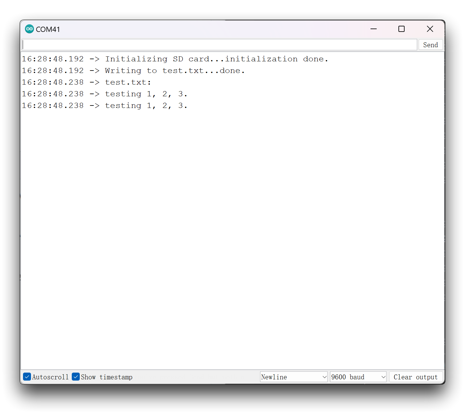
This program will create a new program called test.txt on your microSD card and write the contents of testing 1, 2, 3.. Finally, it reads the file and prints out the contents of the file through the serial monitor.
You will find that the screen TFT initialization is used in the program for the SD card. Please do not think that this is useless and can be removed, but in fact it is necessary to use the SD card, otherwise you will get an error message that the microSD card failed to mount.
Due to the hardware design, some of the pins are low by default, which will cause the microSD mount program to think there is no pull-up resistor causing the mount to fail. So when using the SD card function with Round Display, please make sure to initialize the screen display before initializing the SD card.
XIAO nRF52840
If you are using the XIAO nRF52840 series then you may need to download the SdFat library separately in order to use the SD card function.
#include <SPI.h>
#include "SdFat.h"
#include <TFT_eSPI.h>

TFT_eSPI tft = TFT_eSPI();
SdFat SD;

#define SD_CS_PIN D2
File myFile;

void setup() {
  // Open serial communications and wait for port to open:
  Serial.begin(9600);
  while (!Serial) {
    ; // wait for serial port to connect. Needed for native USB port only
  }

  // Display initialization
  tft.init();

  Serial.print("Initializing SD card...");

  if (!SD.begin(SD_CS_PIN)) {
    Serial.println("initialization failed!");
    return;
  }
  Serial.println("initialization done.");

  // open the file. note that only one file can be open at a time,
  // so you have to close this one before opening another.
  myFile = SD.open("/test.txt", FILE_WRITE);

  // if the file opened okay, write to it:
  if (myFile) {
    Serial.print("Writing to test.txt...");
    myFile.println("testing 1, 2, 3.");
    // close the file:
    myFile.close();
    Serial.println("done.");
  } else {
    // if the file didn't open, print an error:
    Serial.println("error opening test.txt");
  }

  // re-open the file for reading:
  myFile = SD.open("test.txt");
  if (myFile) {
    Serial.println("test.txt:");

    // read from the file until there's nothing else in it:
    while (myFile.available()) {
      Serial.write(myFile.read());
    }
    // close the file:
    myFile.close();
  } else {
    // if the file didn't open, print an error:
    Serial.println("error opening test.txt");
  }
}

void loop() {
  // nothing happens after setup
}
XIAO ESP32S3 & XIAO ESP32S3 Sense & XIAO ESP32C3
Since the ESP32 series has very powerful file system support, we have written a series of examples for the XIAO ESP32 on how to use the file system and save the microSD card, which you can learn to use in the links below.
The tutorials in this Wiki apply to the XIAO ESP32 series, but since you now want to use the Round Display's SD card slot, and the above tutorial focuses on using the SD card slot on the XIAO ESP32S3 Sense, you will need to modify the initialization of the SD card to the line below.
// Display initialization
tft.init();

pinMode(D2, OUTPUT);
SD.begin(D2);
Don't forget that you also need to initialize the TFT screen first to use the SD card function.
Screen function
In the use part of the screen, the two main components are divided into touch and display.
Touch function
Touch function is a special feature of Round Display. You can use the touch function to perform some tap-and-hold display operations.
The following program can be used to output the result of whether the display was touched or not.
#define USE_TFT_ESPI_LIBRARY
#include "lv_xiao_round_screen.h"

void setup() {
  // put your setup code here, to run once:
  Serial.begin(115200);
  pinMode(TOUCH_INT, INPUT_PULLUP);
  Wire.begin();
}

void loop() {
  // put your main code here, to run repeatedly:
  if(chsc6x_is_pressed()){
    Serial.println("The display is touched.");
  }
  else
    Serial.println("The display is not touched.");
  delay(50);
}
The following program is a simple example of a touch function combined with a display function. Upload the following program and then tap the screen, a small circle will be drawn at the location where the screen is tapped.
If you are using XIAO nRF52840, then the following program based on TFT library display may not work properly, you need to modify the program to use Arduino GFX library.
#include <TFT_eSPI.h>
#include <SPI.h>
#define USE_TFT_ESPI_LIBRARY
#include "lv_xiao_round_screen.h"

lv_coord_t touchX, touchY;

void setup() {
  // put your setup code here, to run once:
  Serial.begin(115200);

  pinMode(TOUCH_INT, INPUT_PULLUP);
  Wire.begin();

  // Initialise the screen
  tft.init();

  tft.setRotation(0);
  tft.fillScreen(TFT_BLACK);
}

void loop() {
  // put your main code here, to run repeatedly:
  if(chsc6x_is_pressed())
  {
    Serial.println("The display is touched.");
    chsc6x_get_xy(&touchX, &touchY);
    tft.drawCircle(touchX, touchY, 15, TFT_WHITE);
  }

  delay(50);
}
Display Functions
About the display part, we mainly introduce the use of LVGL library and TFT library. Due to the space issue, we will go into details on how to draw complex dials using the supported graphics libraries in a new Wiki.
Using LVGL and TFT on the Seeed Studio Round Display for XIAO
Of course, if you just want to implement some simple examples, the graphics library also has a very rich set of examples for your reference use.
If you already have these libraries installed, you can easily find the examples inside File->Example->library name on the Arduino IDE.

The examples here are for reference only and not every example will necessarily work. You may need to modify the program to be compatible with the Round Display pinout and hardware definition.
Tech Support & Product Discussion
Q1: Why do I get an error when I use XIAO nRF52840 (Sense)?
When using the content of this tutorial, two different types of problems may occur for the XIAO nRF52840.
- Compatibility issues between nRF52840 and TFT library.
If you are using TFT library, compile and upload without any error, very smooth. But when you are displaying it, you find that there is no image. Then you may have encountered a compatibility issue between nRF52840 and TFT library. This means you can only replace XIAO or use Arduino GFX library to finish the image.
- Compilation error caused by choosing the wrong development board.
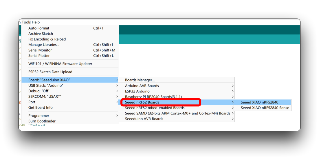
If you are having problems with the compilation process. The error message is usually about an SPI error, for example 'SPI_X' was not declared in this scope. Then it means that you are choosing the wrong type of development board. To use all of this tutorial, you need to use the non-mbed version of the XIAO nRF52840. -->
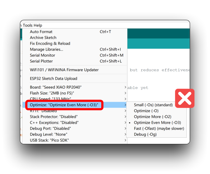
Q2: When uploading a program for XIAO RP2040, an error occurs: unaligned opcodes detected in executable segment?
Please modify the upload options of XIAO RP2040 according to the settings in the image below. All options work fine except the default Small (-Os) (standard).
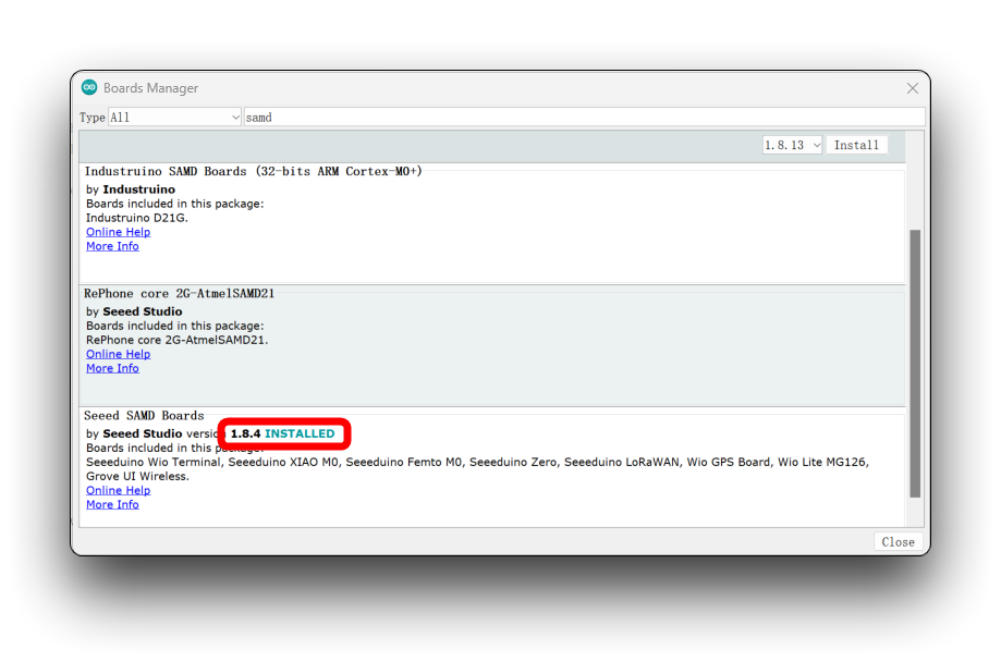
Q3: Why do I get a pin definition error when I compile a circular screen program for the XIAO SAMD21?
When you encounter this error, please update your Seeed SAMD development board on-board package to the latest version.
Q4: Why does the screen not display after I upload the program to XIAO ESP32C3?
If there is no problem with the program and it does not show up after uploading it may be that it needs to be reset. Just press the reset button on the XIAO ESP32C3.
Tech Support & Product Discussion
Thank you for choosing our products! We are here to provide you with different support to ensure that your experience with our products is as smooth as possible. We offer several communication channels to cater to different preferences and needs.