reBot Arm 102 + B601 DM Training Guide
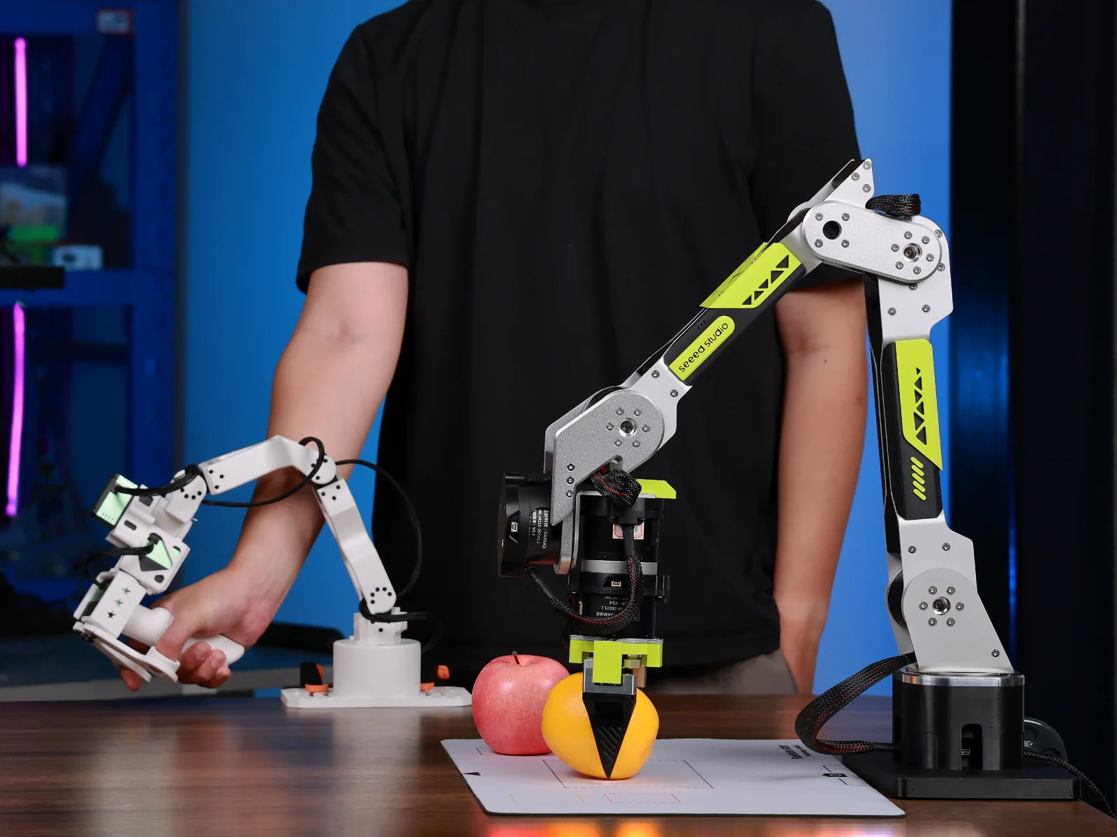
This tutorial uses the reBot Arm 102 (leader arm) and B601 DM (follower arm) with SenseCraft Robotics to present the complete workflow, from project creation and device setup to data collection, model training, and operation. The example task in this guide is to pick up an object at Point A and place it at Point B. It is provided for illustration only; users can design application scenarios according to their needs, such as sorting, handling, boxing, button pressing, or plugging and unplugging.
Version note Interface names, button locations, and training backends may change with SenseCraft Robotics versions. Serial port numbers (such as COM21, COM35, COM3, and COM6) and dataset names in this guide are examples from a video. Always use the devices detected by your current computer.
Tutorial Overview
This tutorial is organized in the order of hardware setup and software operation to help you quickly configure the arms and train a model:
| Chapter | Stage | Key content |
|---|---|---|
| Chapter 1 | Preparation | Hardware list, computer and software requirements, scene and safety checks |
| Chapter 2 | Connect the Arms | Physical mounting and cable connections for the leader and follower arms |
| Chapter 3 | Software Training | Core workflow: device setup ➔ data collection ➔ model training ➔ deployment and operation |
1. Preparation
1.1 Hardware
The arms must be assembled, mounted, powered, and connected to USB. If assembly is not complete, refer to Step 1: Assemble the Arm.
Arms
| Category | Leader: reBot Arm 102 | Follower: B601 DM |
|---|---|---|
| Arm | reBot Arm 102 ×1 🔗Buy now | Assembled reBot Arm B601-DM kit (assembled gripper version with power supply) ×1 🔗Buy now |
| Power supply | 12 V / 2 A power adapter ×1 | 24 V / 15 A power supply and power cable ×1 |
| Data cable | USB-C data cable ×1 | USB-C data cable ×1 |
| Communication and power components | — | USB-CAN driver board ×1 Signal/power separation board ×1 |
| Other cables | — | 2-pin JST cable ×1 3-pin JST cable ×1 XT30 2+2 cable ×1 |
| Mounting tools | G-clamp ×2 | G-clamp ×2 |
Cameras
Two cameras are required: one for the top view, and one for either the side view or the gripper view.
| Camera | Top-view camera | Side-view camera | Gripper camera |
|---|---|---|---|
| Quantity | 1 | Choose either the side-view or gripper camera | |
| Mount | Top-view mount ×1 | Small desktop mount ×1 | 3D-printed mount ×1 |
Camera options: On macOS or Windows, choose any of the following combinations. We recommend connecting the cameras directly to the computer's USB ports instead of using a USB hub or dock.
| Option | Hikvision USB camera | Logitech C270 HD Webcam | Collection performance |
|---|---|---|---|
| Option1 | 1 | 1 | Most stable; supports 120 FPS collection |
| Option2 | ❌ | 2 | Stable; supports all collection frame rates |
| Option3 | 2 | ❌ | Keep the frame rate at or below 60 FPS; 120 FPS collection is not supported and compatibility issues may occur in some cases |
1.2 Computer and Software
- Windows or macOS computer (local training requires a compatible GPU)
- Stable network connection (for downloading, logging in, cloud training, and inference)
- SenseCraft Robotics installed
- A registered SenseCraft account, signed in within SenseCraft Robotics
For detailed instructions, refer to Software Download and Account Setup.
1.3 Scene and Safety
- Mark two fixed positions on the table: Point A for the object's starting position and Point B for its destination.
- Prepare an object that is appropriately sized and easy to grasp, such as a red block or a soft object.
- Make sure Point A, Point B, both arms, and the object are within the camera views and are not obstructed.
- Clear the arm workspace of people, clutter, cables, and fragile objects. Adjust the leader arm so that it does not approach the follower arm or appear in the follower camera view.
2. Connect the Arms
Safety notice: Disconnect the power before connecting or disconnecting JST, XT30, or other cables. Turn the power on only after confirming that all cables are connected correctly. B601 RS and B601 DM look similar. Make sure you distinguish between them.
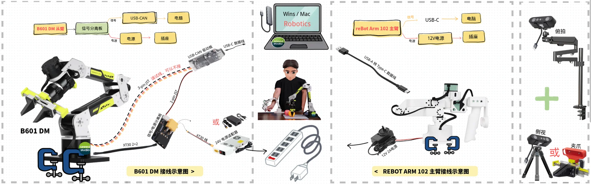
2.1 Mount and Connect the reBot Arm 102 (Leader Arm)
Step 1: Mount the reBot Arm 102
Use woodworking clamps to secure the reBot Arm 102 to a flat tabletop. Gently push the base to confirm that it does not move.
Step 2: Connect the Cables

The connections consist of two paths:
-
Signal path (arm -> USB-C cable -> computer)
- Prepare a USB-C cable to connect the arm to the computer (do not plug it into the computer yet; connect it when you reach serial-port binding and scan for devices).
-
Power path (arm -> 12 V 2 A power adapter -> power strip -> power on)
- Connect the 12 V 2 A power adapter to the arm's power connector.
- Connect the adapter to the power strip to power on the arm.
2.2 Mount and Connect the B601 DM (Follower Arm)

Step 3: Mount the B601 DM
Use G-clamps to secure the B601 DM to a stable, flat tabletop. After securing it, gently rotate the arm left and right to confirm that the base does not move.
Step 4: Connect the Cables
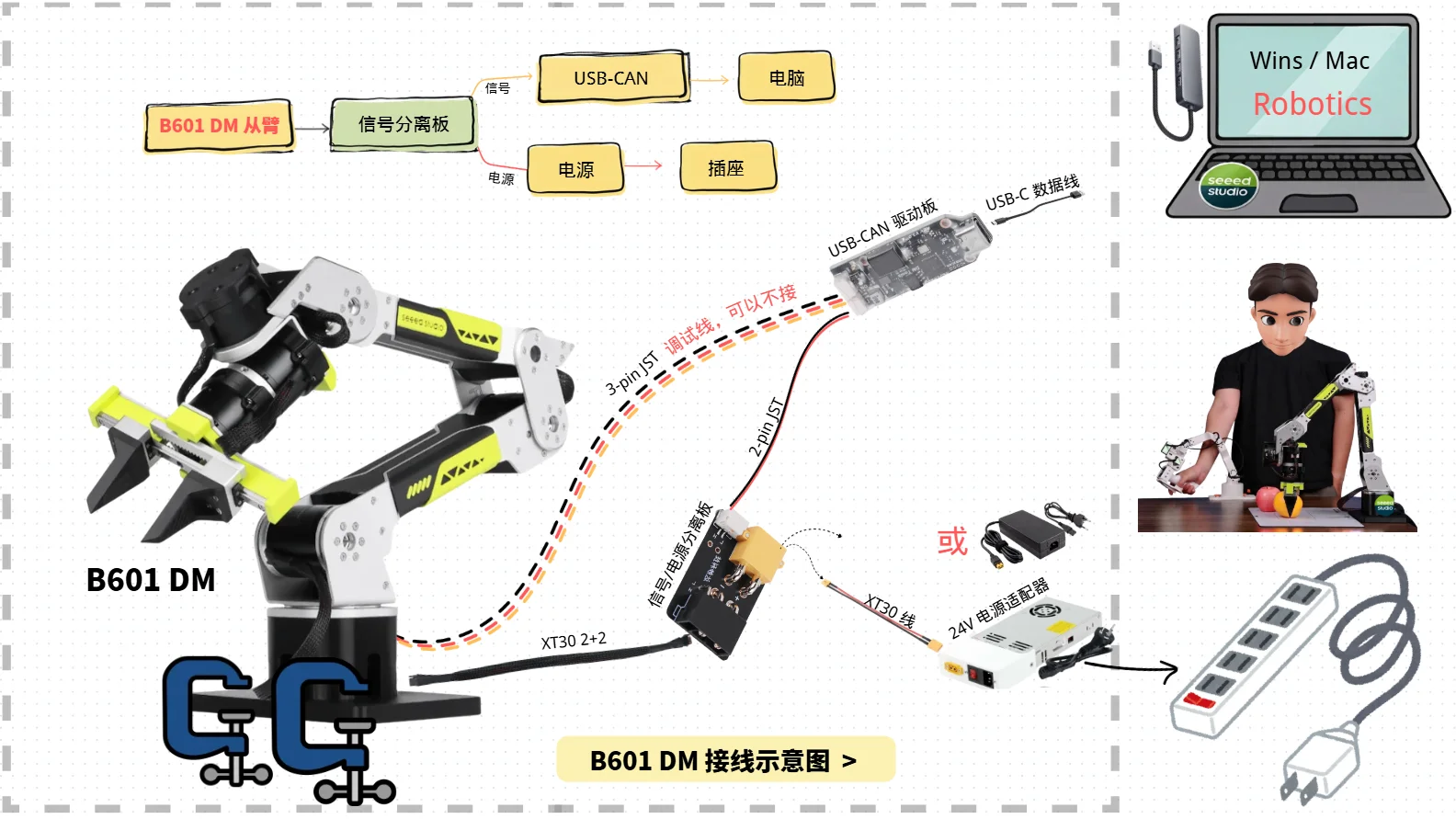
Make sure the power is disconnected before starting. The connections consist of two paths:
-
Signal path (arm -> signal/power separation board -> USB-CAN driver board -> computer)
- Use an XT30 2+2 cable to connect the first motor at the bottom to the signal/power separation board.
- Use the 2-pin JST cable to connect the signal/power separation board to the USB-CAN driver board.
- Use the 3-pin JST cable to connect the first motor at the bottom to the USB-CAN driver board (this is a debug cable and may be left disconnected).
- Prepare a USB-C data cable to connect the USB-CAN driver board to the computer (do not plug it into the computer yet; connect it when you reach serial-port binding and scan for devices).
-
Power path (arm -> signal/power separation board -> 24 V power adapter -> outlet -> power on)
- Use an XT30 2+2 cable to connect the first motor at the bottom to the signal/power separation board.
- Connect the signal/power separation board to the 24 V power adapter.
- Connect the power adapter to the outlet. After confirming that the arm is secured, the cables are correct, and the surrounding area is clear, turn on the power.
3. Project
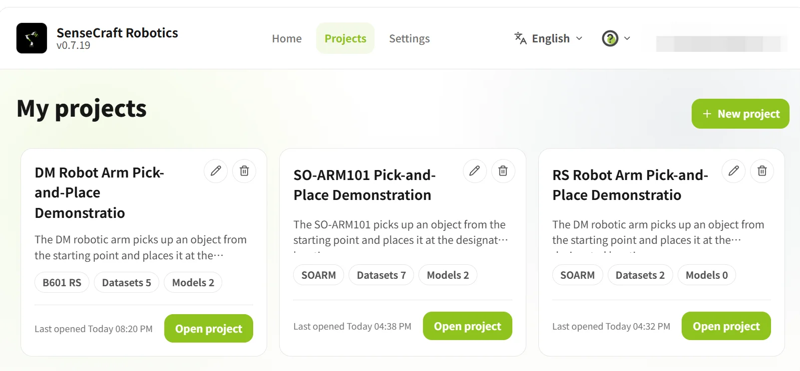
After signing in, open the Projects page. Create a new project for first-time use, or open an existing project. In a project, the Project Overview provides access to device setup, action replay, datasets, training, models, and operation.
| Operation | Steps |
|---|---|
| Create a project | Click New Project → enter the project name and description → click Create and Start |
| Open an existing project | Select a project from the project list → open the project |
3.1 Project Overview
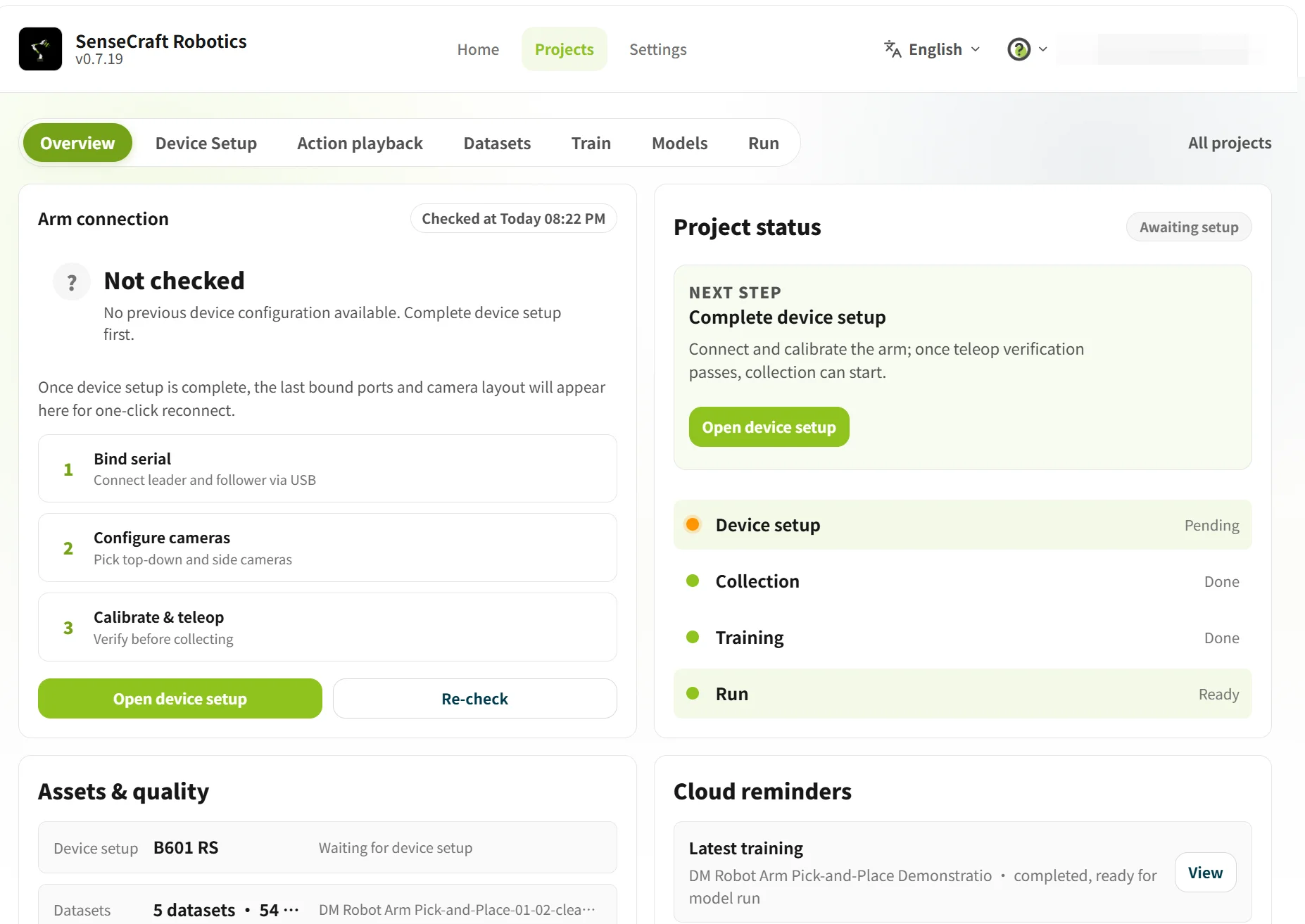
Project Overview displays the current project status, including arm connection, device setup, dataset, training, model, and operation status.
If the page shows Pending configuration or Not connected, click Go to Device Setup to configure the arms.
3.2 Device Setup
Device Setup is used for device selection, serial-port binding, arm calibration, teleoperation verification, and camera configuration.
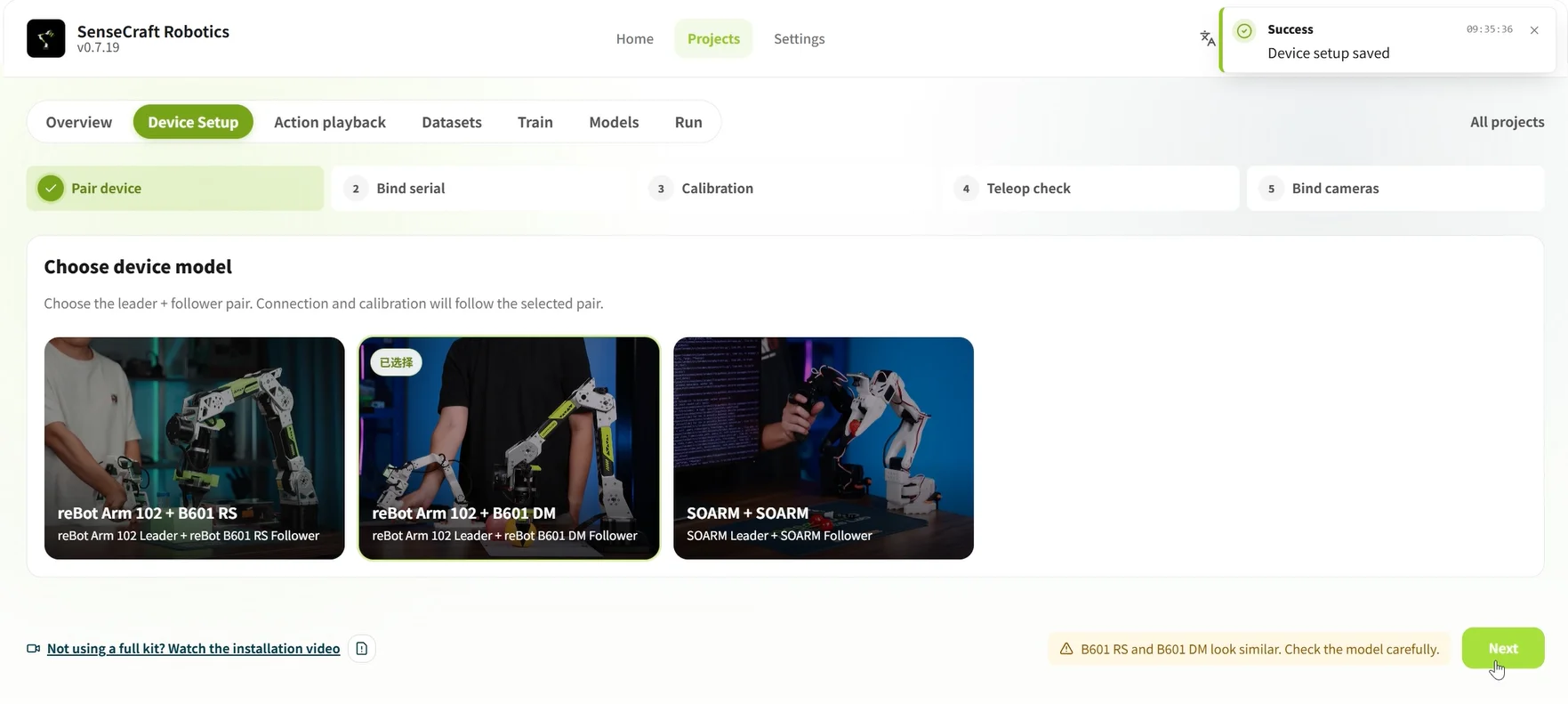
3.2.1 Select the Device Model
In the Device Pairing step, select reBot Arm 102 + B601 DM, then click Next to bind the serial ports.
3.2.2 Bind the USB Serial Ports for the Leader and Follower Arms
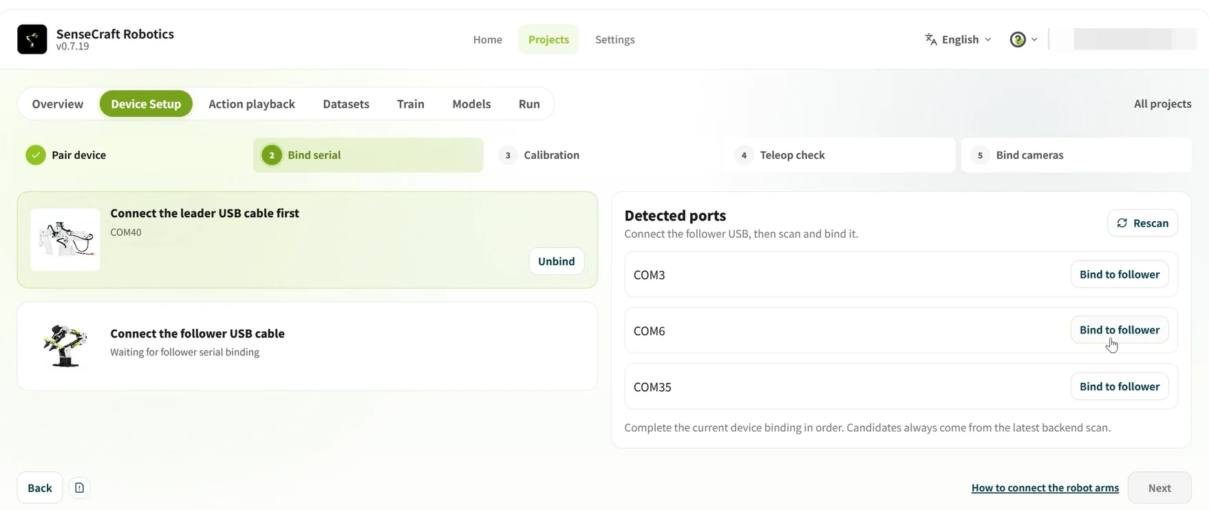
- Initial scan: Disconnect the USB cables from both arms, click Rescan, and note the serial ports currently displayed.
- Bind the leader arm: Connect the reBot Arm 102 (leader arm), click Rescan again, and bind the newly detected serial port to the leader arm.
- Bind the follower arm: Connect the B601 DM (follower arm), click Rescan again, and bind the newly detected serial port to the follower arm.
- Confirm that both arms show Connected, then click Next.
Serial-port binding and troubleshooting:
- After each scan, bind only the newly detected serial port. Do not identify a device only by its COM number.
- If a serial port is not shown, reconnect the USB cable and scan again. If only one serial port is shown, check the other USB cable and the device power.
3.2.3 Arm Calibration Verification

- Follow the on-screen example to place the leader and follower arms in their initial poses, and confirm that the workspace is clear.
- Click Start Calibration, then follow the on-screen instructions to complete leader-arm zeroing, follower-arm zeroing, and calibration completion.
- If the arm poses are inconsistent or calibration fails, click Recalibrate and do not continue to the next steps.
Do not perform teleoperation or data collection before calibration is complete.
3.2.4 Teleoperation Verification
Teleoperation verification confirms that the follower arm correctly follows the leader arm. If the direction is reversed, the delay is excessive, or the motion is discontinuous, check the device roles, serial-port binding, and calibration result.
- Click Start Teleoperation.
- Move the leader arm through a small range and observe whether the follower arm moves synchronously, in the same direction, and smoothly.
- After completing the check, click End Teleoperation, then select an option based on the result:
- Normal: Click Confirm Teleoperation Normal.
- Abnormal: Click Abnormal, Return to Recalibrate.

Gravity compensation (optional) The arm has some weight, so manually adjusting the follower arm may require effort. When gravity compensation is enabled, the system offsets part of the weight and makes the follower arm easier to move. After adjustment, turn gravity compensation off before performing teleoperation verification. Gravity compensation is for adjusting the follower arm; it is not used to control the follower arm during leader-follower operation.
3.2.5 Bind the Cameras
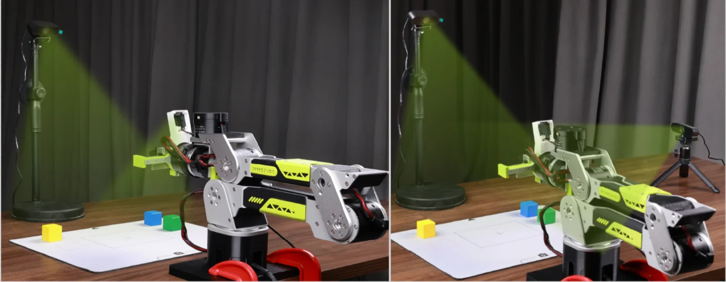
Cameras record visual information while the arm performs a task. The following are two common camera layouts:
| Layout | Installation and purpose | Suitable scenarios | Illustration |
|---|---|---|---|
| Gripper view | Top-view camera: Install it above the front of the worktable to cover the work area. Gripper camera: Install it near the gripper to observe grasping details. | Fine operations that require observing contact between the gripper and the object. | 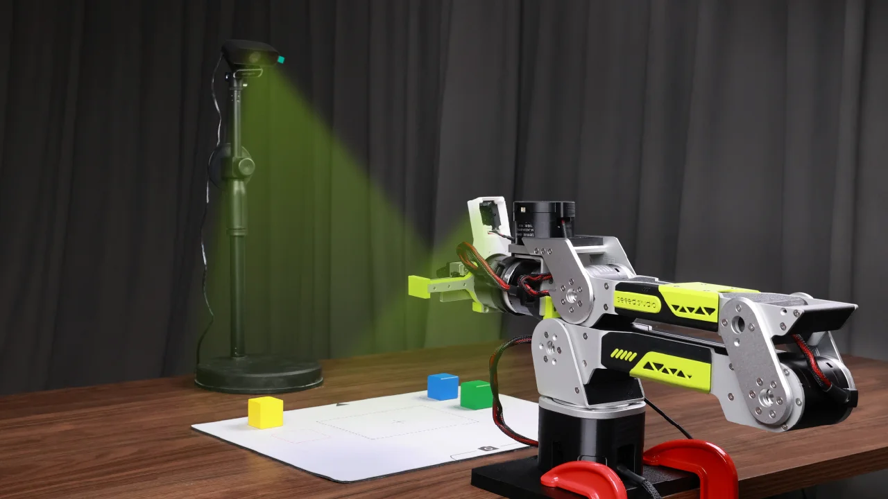 *Note: You may design the 3D camera mount yourself. |
| Side-view assistance | Top-view camera: Install it above the front of the worktable to cover the work area. Side-view camera: Install it at the front side of the worktable to observe the arm height and gripper motion. | Pick-and-place, handling, and placement tasks. | 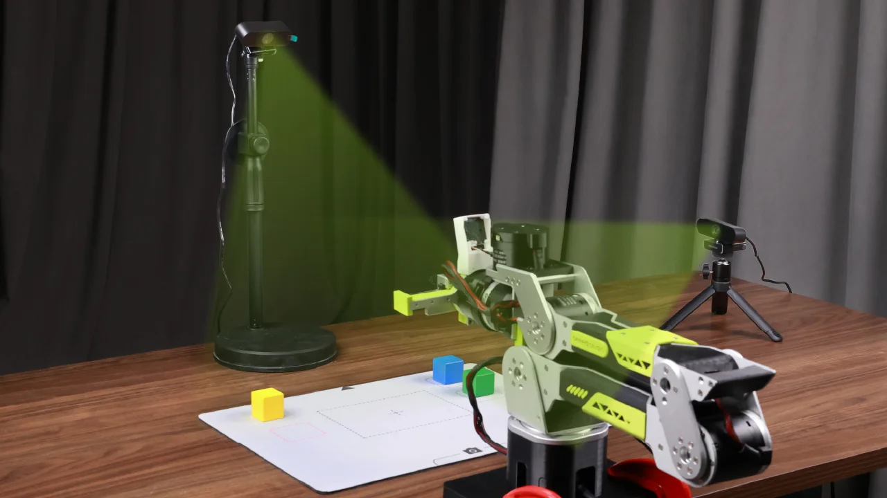 |
This tutorial uses the side-view assistance layout. After installing and positioning the cameras:
- Connect the cameras to the computer and click Rescan.
- Select the corresponding video streams in the Top-view camera and Side-view camera sections.
- Check both preview windows to confirm that the arms, object, and target positions are clearly visible. Click Next after confirming the setup.
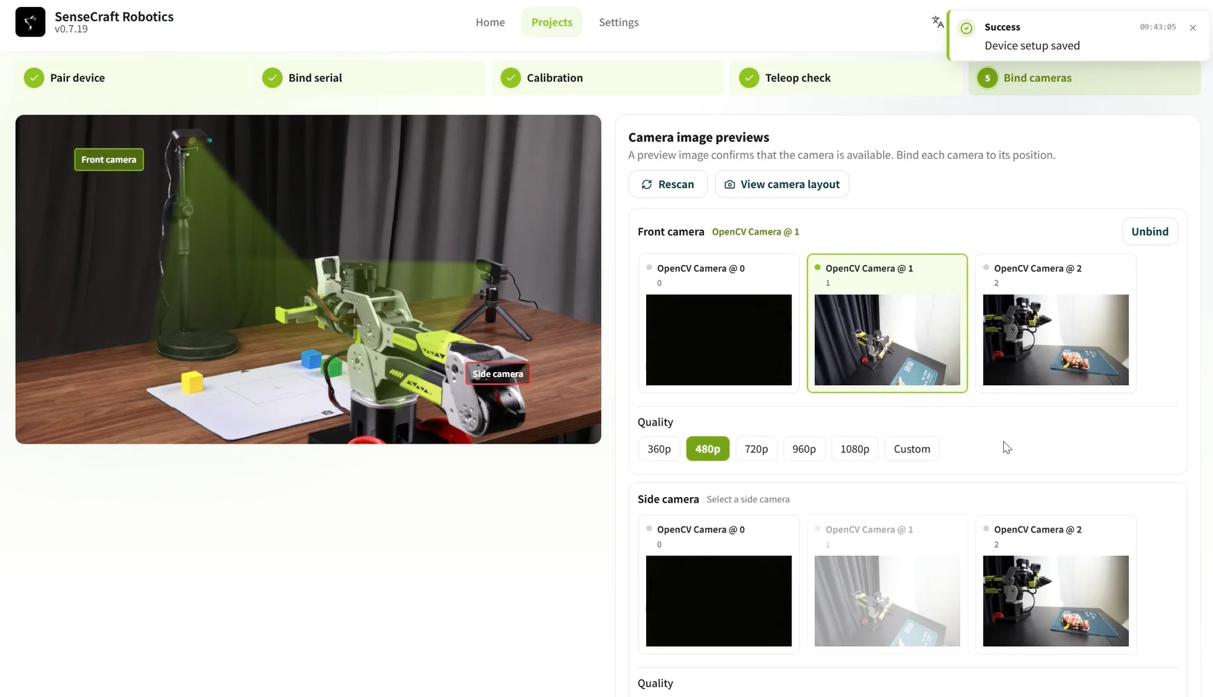
To confirm that each camera matches its installation position, click View Camera Layout. If a preview is black or abnormal, rescan, restart the camera, or use another USB port.
3.3 Action Replay
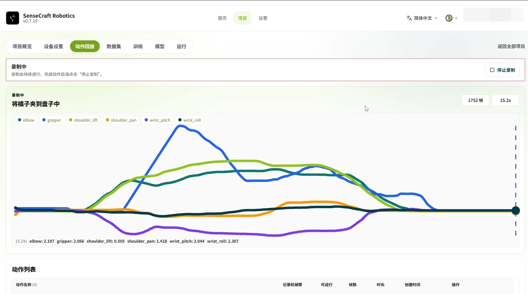
Action Replay records arm motions through leader-arm teaching and saves them in the action list for replay. After recording, check whether the motion is continuous and whether the movement direction and gripper opening and closing are normal.
| Function | Operation | Purpose |
|---|---|---|
| Record an action | Click + to create an action → use the leader arm to control the follower arm and complete the task → click Stop Recording → save | Record target actions such as grasping, moving, and placing |
| Replay an action | Click Replay | Check whether the action is complete and continuous, and confirm the movement direction and gripper opening and closing |
Before recording an action for the first time, complete device connection and teleoperation verification in Device Setup, and click Confirm Teleoperation Normal. If replay is abnormal, delete the action and record it again.
3.4 Dataset
Dataset is used to create collection tasks and record, inspect, clean, and merge task episodes. We recommend collecting data in small batches so that device disconnections, software errors, or video stutter can be found early and the risk of losing all data because of one failure is reduced.
- Record about 10 task episodes per batch first.
- After completing 2–3 batches, keep about 20–30 valid episodes for the first training run.
- Add more data for complex tasks according to the training results.
3.4.1 Configure a Data Collection Task
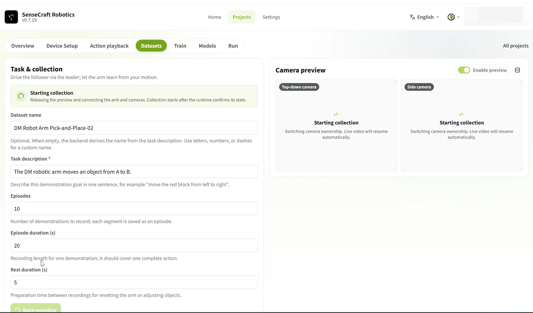
Open Dataset → Collect Data at the top of the page and enter the task information. If multiple datasets will be merged, the task description in each batch must be exactly the same. Before collection, also keep the A and B positions, object category, camera positions, table background, and lighting conditions as stable as possible.
| Field | Example value | Instructions |
|---|---|---|
| Dataset name | DM Arm Pick-and-Place from A to B-01 | Use a “device + task + batch” naming scheme |
| Task description | Move the object from the left to the right | Clearly describe the task objective; descriptions must be exactly the same when batches are merged |
| Number of episodes | 10 | Each episode should contain one complete task |
| Episode duration | 20–30 seconds | Cover the complete action sequence |
| Rest duration | 5 seconds | Allow time to reset the arm and adjust the scene |
3.4.2 Record Task Episodes
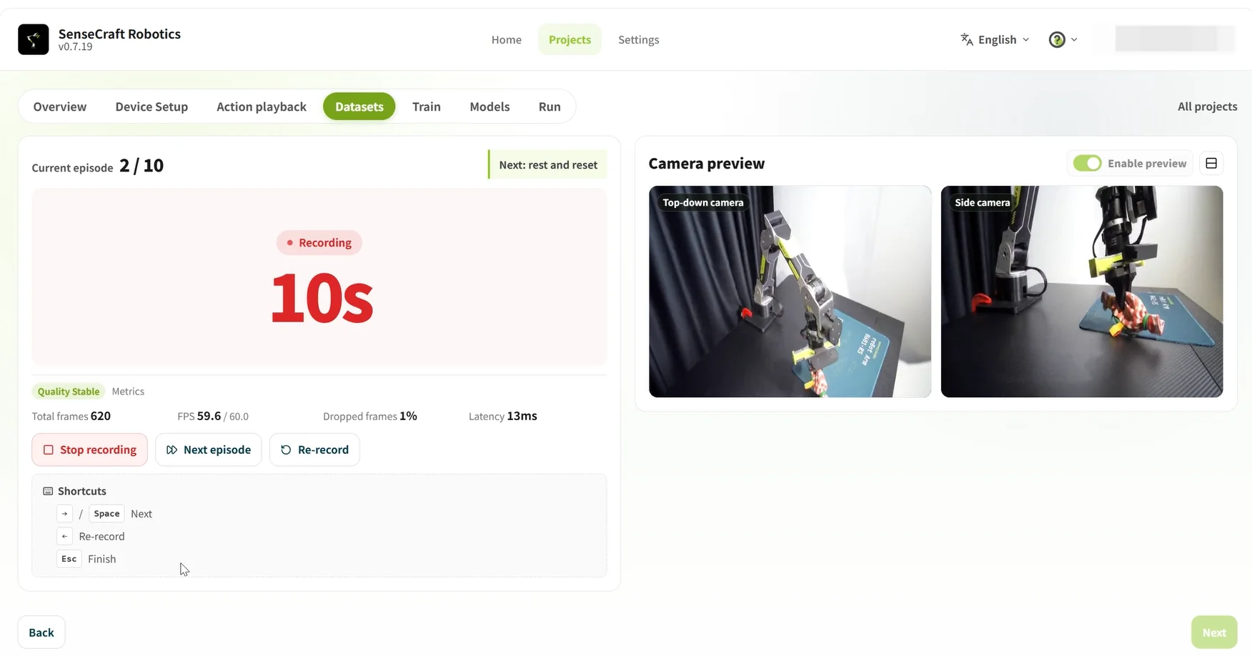
Recording task episodes is the core of the training data. Each episode should completely record picking up the object at Point A, moving it to Point B, and putting it down. To help the model learn quickly, keep the task flow generally consistent. To improve generalization, add data with different positions, angles, and motion variations.
- Place the object at Point A, confirm that the arm is in its initial pose, and click Start Recording.
- Use the leader arm to control the follower arm and complete the task, then return the arm to its initial pose.
- After completing the task, wait for the remaining time to finish, or click the arrow (or press the space bar) to end the current episode early.
- During the rest period, return the object to Point A and confirm that the arm is ready. Start the next episode when the rest period ends.
Important ⚠️
- Before collection, adjust and secure the cameras. Make sure the arms, gripper, object, and Points A and B are all visible in the camera views.
- Key actions must not be 🚫 obstructed or outside the camera views; otherwise, the data may not be usable for training.
- If a task fails, the object is not grasped securely, the video stutters, or a camera is obstructed, click Retake Immediately or press
Escto stop collection.- You can finish the current batch first, then inspect and delete abnormal episodes.
- If there is a risk of loss of control or collision, stop 🛑 immediately.
3.4.3 Inspect, Delete, and Merge Data
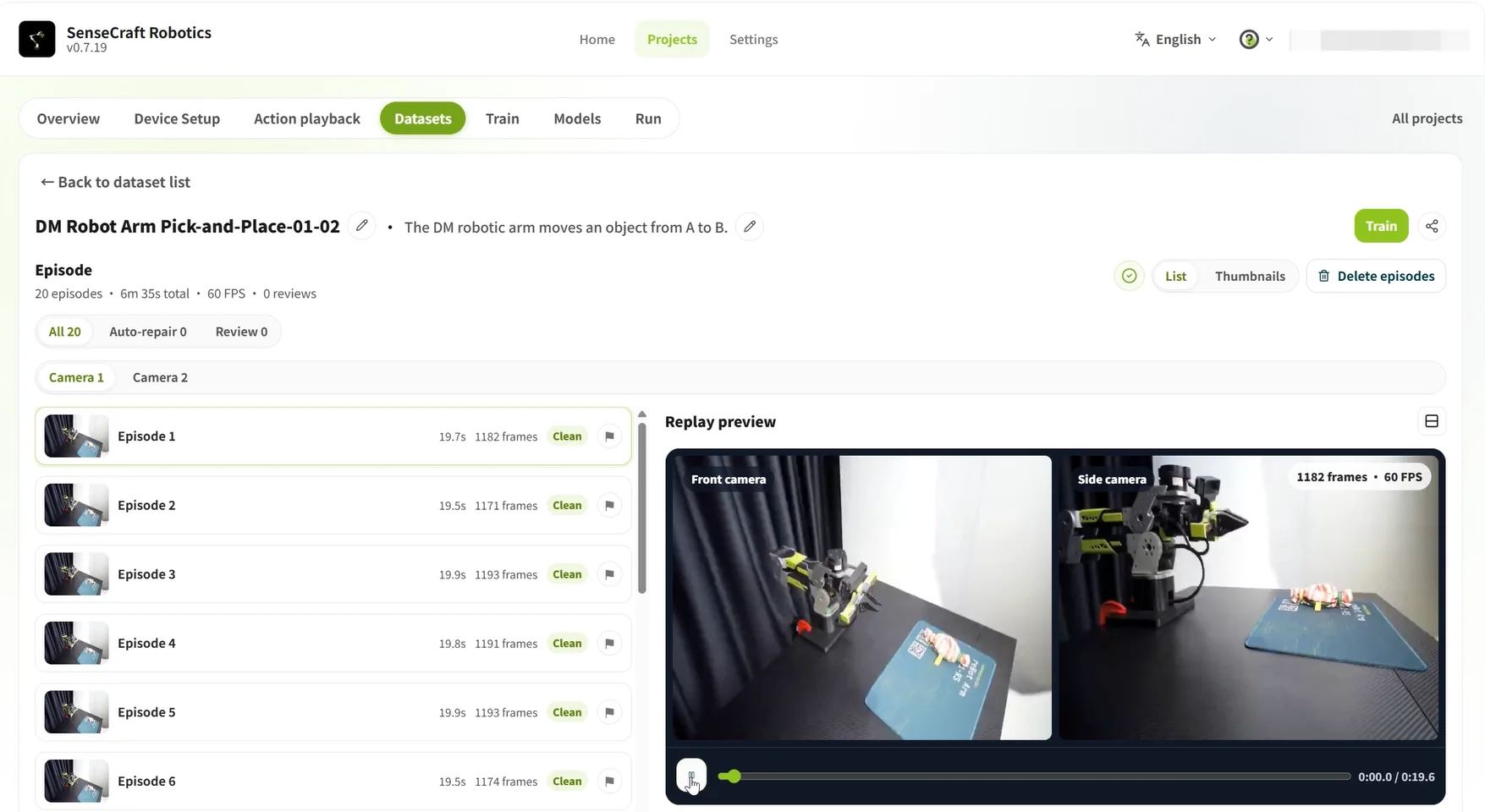
After collection, inspect abnormal episodes, delete invalid data, and merge multiple datasets when needed.
| Operation | How to perform it | Description |
|---|---|---|
| Inspect abnormal episodes | Select an episode and play its video or replay its action | Confirm that the task was completed and the gripper motion was normal. Note abnormal episode numbers during recording so that you can inspect them directly later |
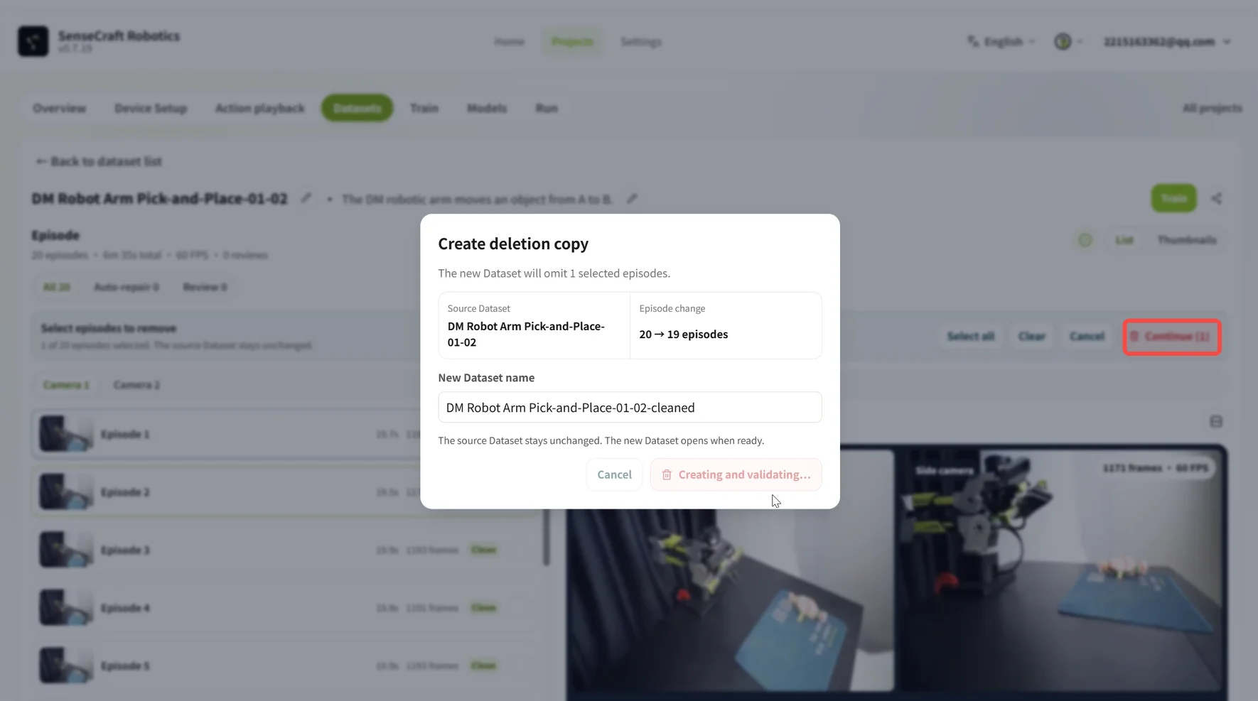
| Delete abnormal episodes | Click Batch Delete Episodes, select the abnormal episodes, and confirm; then click Generate Deleted Copy | Change the new dataset name and confirm. The original dataset will not be overwritten |
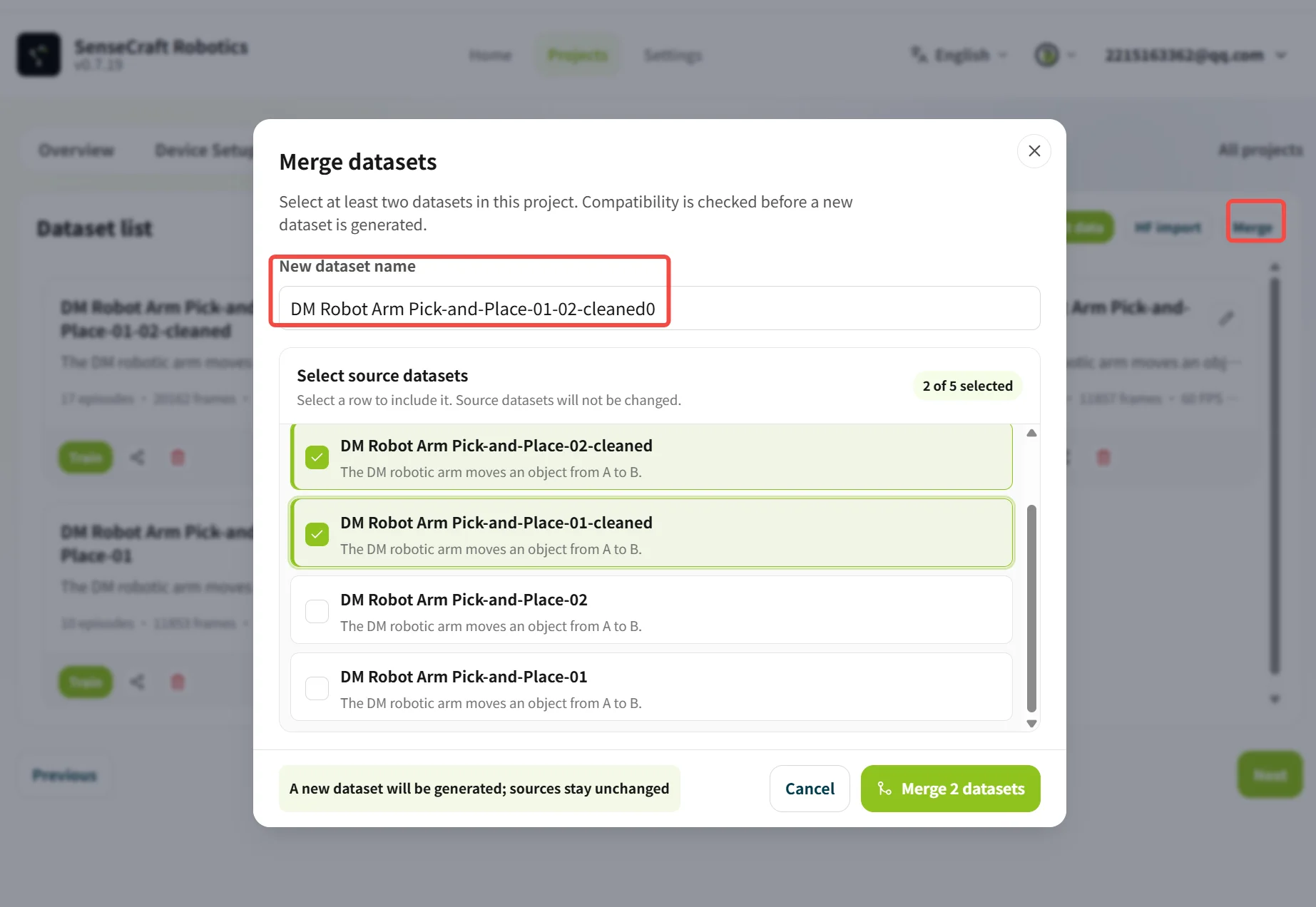
| Merge datasets | Click Merge, select the datasets, and enter a new dataset name | We recommend merging datasets with the same task description, device combination, and camera configuration |
3.5 Training
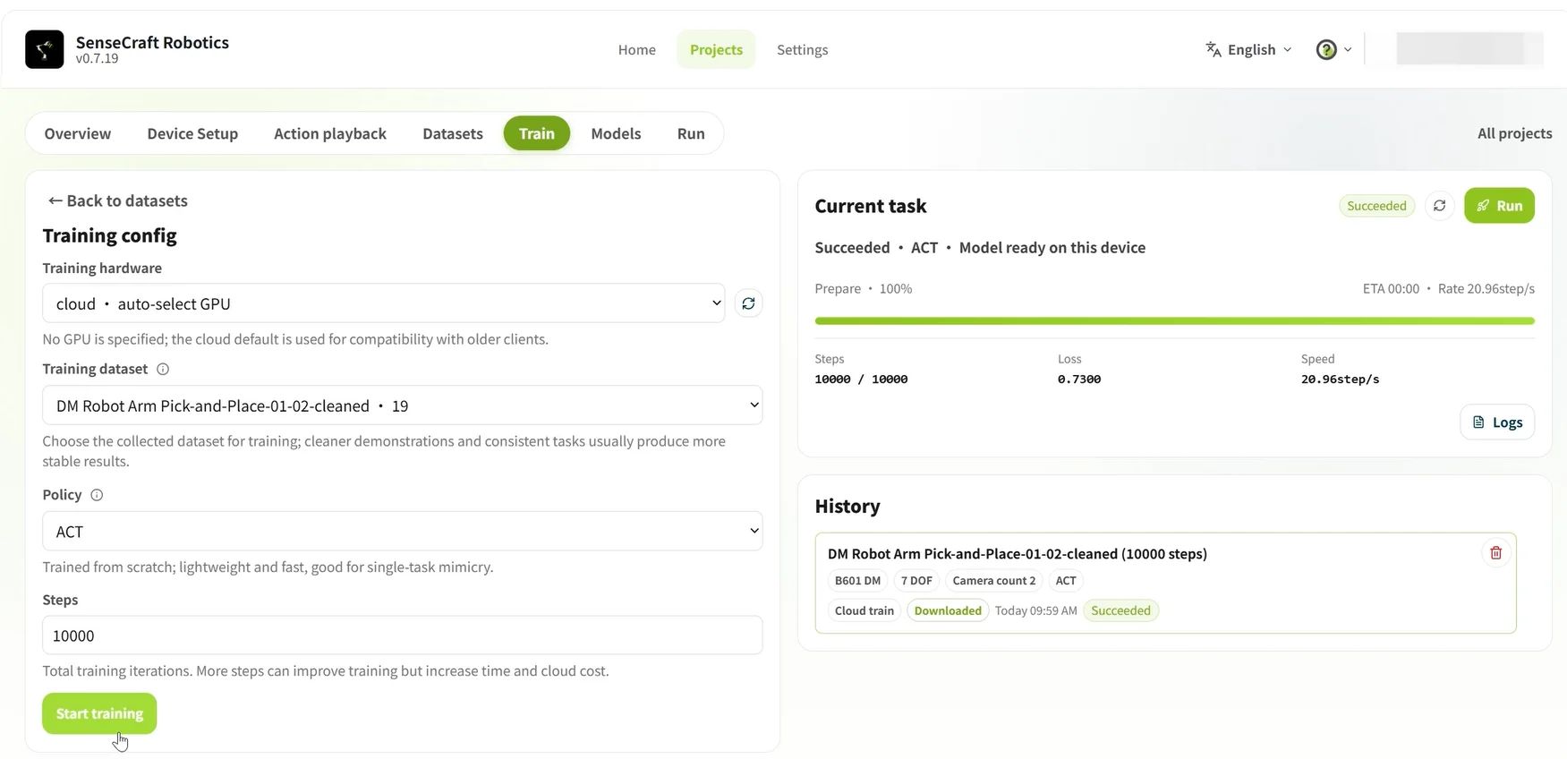
Training generates an action model for the arm (that is, an action-control program formed from the demonstration data). SenseCraft Robotics reads the recorded task data, analyzes how the arm completes the objective, and generates a model that can be used for automatic operation.
Use the following table to configure the training parameters:
| Parameter | Option / value | Details |
|---|---|---|
| Training hardware | Cloud · Auto-select GPU | Uses a cloud server for training and consumes the corresponding credits. |
| Local · Free | Uses the current computer for training and does not consume credits, but requires a compatible local GPU. | |
| Training dataset | Select the target dataset | Select the recorded dataset prepared for this training run. |
| Policy | ACT | The default action-control policy currently used. |
| Training steps | 10000 | We recommend entering 10000 as the initial value and adjusting it according to the model's actual performance. |
Credit note Cloud · Auto-select GPU training consumes credits; Local · Free training does not consume cloud training credits. For credit acquisition, usage, and rules, refer to Credit Rules.
Training steps and episode recommendations:
| Task difficulty | Task description | Recommended episodes | Recommended training steps |
|---|---|---|---|
| Beginner | Fixed Point A to Point B | About 20 | 10,000–15,000 steps |
| Intermediate | Pick and place at random positions | About 50 | 30,000–40,000 steps |
| Advanced | Many steps or long duration | About 100 | 80,000–100,000 steps |
Training duration: Total training time depends on both the selected GPU model and the number of training steps. For example, training for 20,000 steps (2W) in the cloud on most GPUs usually takes anywhere from several minutes to several tens of minutes. Training for 100,000 steps (10W) takes approximately five times as long as training for 20,000 steps.
After confirming the settings, click Start Training. Once training begins, you can view the progress and historical tasks in the Current Training Tasks list.
3.6 Model
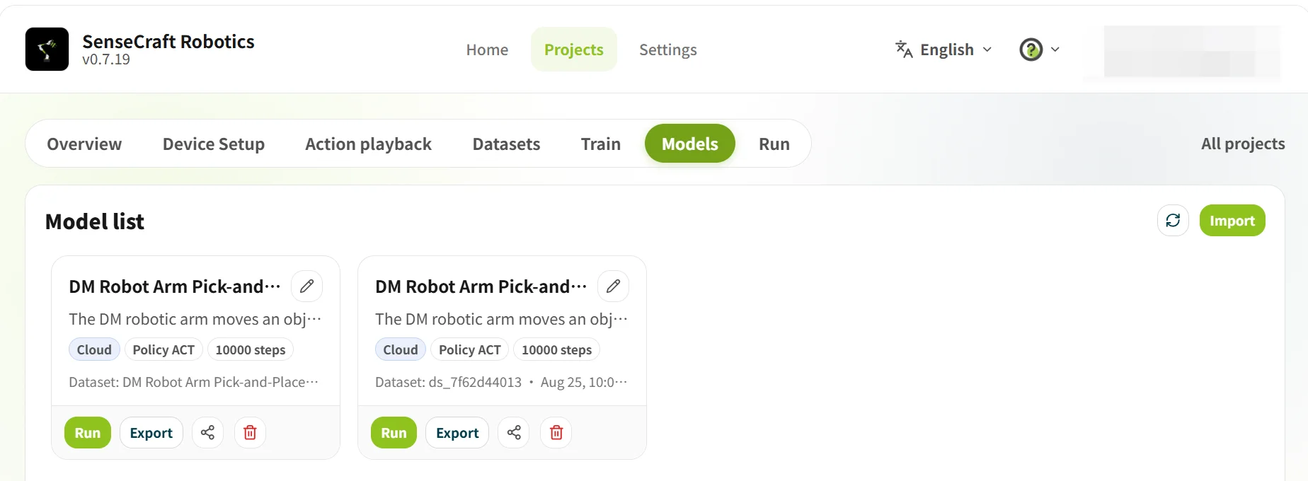
Model is used to view training results and select the model for subsequent operation. Before using a model, confirm that training is complete and that its task and device combination match the current project.
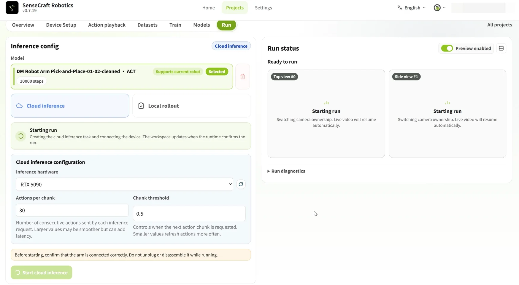
3.7 Operation
Operation loads a trained model onto the arms to verify whether it can complete the task correctly.
Steps:
- Select a model: Select a model labeled Supported by Current Robot Arm.
- Select an inference method: Select Cloud Inference or Local Inference, and configure the corresponding parameters.
- Start inference: After confirming the settings, click Start Inference.
Core differences between Cloud Inference and Local Inference:
| Comparison | Cloud Inference | Local Inference |
|---|---|---|
| Computing hardware | Uses a high-performance cloud GPU for inference. | Uses the computer's local CPU for inference (the current platform does not support using a local GPU). |
| Performance impact | Computing power is strong and generally unrestricted, but the result depends heavily on network transmission quality. | Performance is affected by the local CPU. |
| Parameter configuration | Action count (default: 120): Number of action steps predicted in one inference. Block threshold (default: 0.9): A parameter that affects motion continuity and accuracy. A higher value makes arm execution more cautious (and may cause pauses); a lower value makes motion smoother (but may cause errors). (The default settings are usually sufficient.) | Run count: Total number of times (episodes) to repeat the task continuously. Time limit per run (seconds): Maximum time for one task run; the run ends automatically when the limit is reached. (The default settings are usually sufficient.) |
| Data output | Only performs inference for verification. | After the run ends, the inference content is automatically generated as a corresponding dataset. |
| Cost and limits | Cost is subject to platform rules; the computing power is strong and suitable for quickly starting training. | Usually does not require cloud credits, but is limited by local CPU performance. |
Notes
- Before starting: Confirm that the arms are connected correctly and that the workspace is safe.
- During operation: Do not disconnect or disassemble the arms, and observe whether their movements are normal.
- If the result is unsatisfactory: Return to Dataset, delete abnormal episodes, add valid data, and train again.