SO-ARM101 Training Guide
This tutorial uses an SO-ARM101 Leader arm and an SO-ARM101 Follower arm with SenseCraft Robotics. It covers the complete workflow from project creation and device setup to data collection, model training, and operation.
The example task is to pick up an object at Point A and place it at Point B. It is provided only to explain the procedure. Users can design other application scenarios, such as sorting, handling, boxing, button pressing, or plugging and unplugging.
Version note Interface names, button locations, and training backends may change with SenseCraft Robotics versions. Serial ports such as COM21, COM35, COM3, and COM6, as well as dataset names, are examples from a video. Always use the devices detected by the current computer.
Tutorial overview
This tutorial follows the order of hardware setup and software operation:
| Chapter | Stage | Key content |
|---|---|---|
| Chapter 1 | Preparation | Hardware list, computer and software requirements, scene and safety checks |
| Chapter 2 | Connect the arms | Physical mounting and cable connections |
| Chapter 3 | Software workflow | Core workflow: device setup ➔ data collection ➔ model training ➔ deployment and operation |
1. Preparation
1.1 Hardware
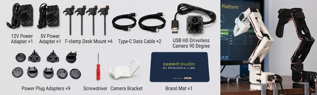
The following list is based on the official Part List supplied with the SO-ARM101 kit.
Leader and Follower accessories
| Item | Leader | Follower |
|---|---|---|
| Arm Buy now | Black assembled Leader arm ×1 | White assembled Follower arm ×1 |
| LeRobot servo control board | ×1 | ×1 |
| Power cable | 5 V power cable (multi-head) ×1 | Pro: 12 V power cable ×1; Standard: 5 V |
| Data cable | USB-C data cable ×1 | USB-C data cable ×1 |
| DC power adapter cable | ×1 | ×1 |
| Mounting clamp | ×2 | ×2 |
Shared materials and accessories
| Accessory | Quantity | Description |
|---|---|---|
| Flexible gripper parts | ×1 | Installed at the arm end |
| 32 × 32 mm USB camera | ×2 | Two cameras are required. The kit includes one; prepare a second camera separately. Training data must contain two views. |
| Screwdriver | ×1 | For assembly and adjustment |
| Mouse mat | ×1 | Protects and stabilizes the work surface |
The arms must be assembled, mounted, powered, and connected by USB. If assembly is not complete, refer to Step 1: Assemble the arm.
Power and connection notes
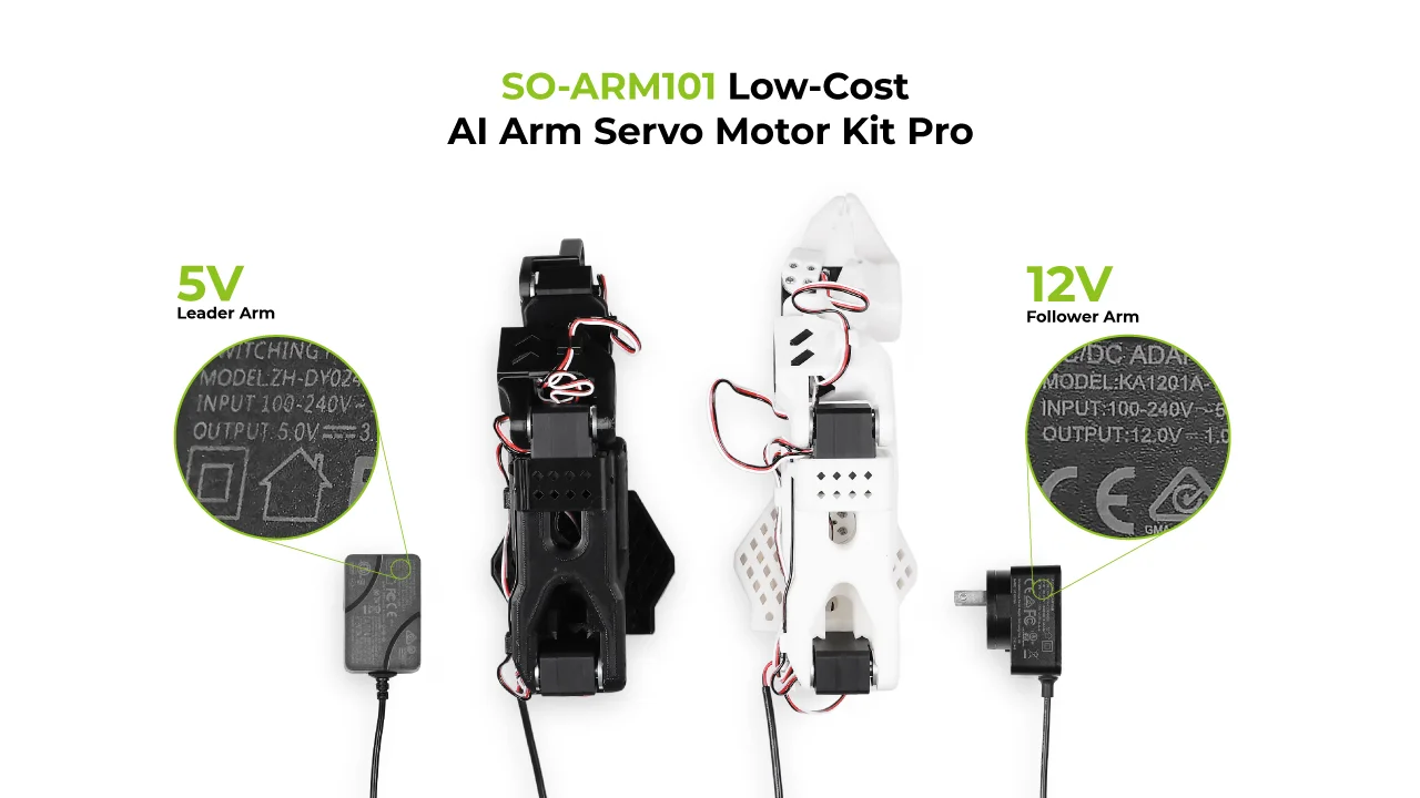
- Standard version: both the Leader and Follower use 5 V power.
- Pro version: the Leader uses 5 V and the Follower uses 12 V. Do not interchange them.
- Check the input voltage, output voltage, and rated current on the adapter label and in the official product documentation for the applicable version.
1.2 Computer and software
- Windows or macOS computer. Local training requires a compatible GPU.
- Stable network connection for downloading, login, cloud training, and inference.
- SenseCraft Robotics installed.
- A registered SenseCraft account, signed in within SenseCraft Robotics.
For detailed instructions, refer to Software download and account setup.
1.3 Scene and safety
- Mark two fixed positions on the table: Point A for the object's starting position and Point B for its destination.
- Prepare an appropriately sized object that is easy to grasp, such as a red block or a soft object.
- Make sure Point A, Point B, both arms, and the object are visible in the camera views and are not obstructed.
- Clear the arm workspace of people, clutter, cables, and fragile objects. Keep the Leader away from the Follower and out of the Follower camera view.
2. Connect the arms
Safety notice: Disconnect the power before installing, connecting, or removing the arms. Confirm that the arms are secure, the cables are connected correctly, and the workspace is clear before restoring power. Never connect or disconnect the power interface while powered.
2.1 Install the arm bodies
Step 1: Mount the Leader and Follower
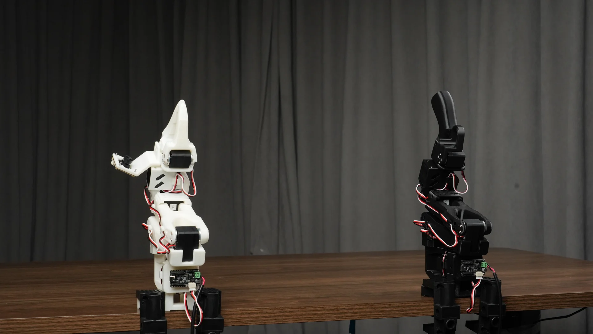
- Place the SO-ARM101 Leader and Follower on a stable, level table or mounting platform.
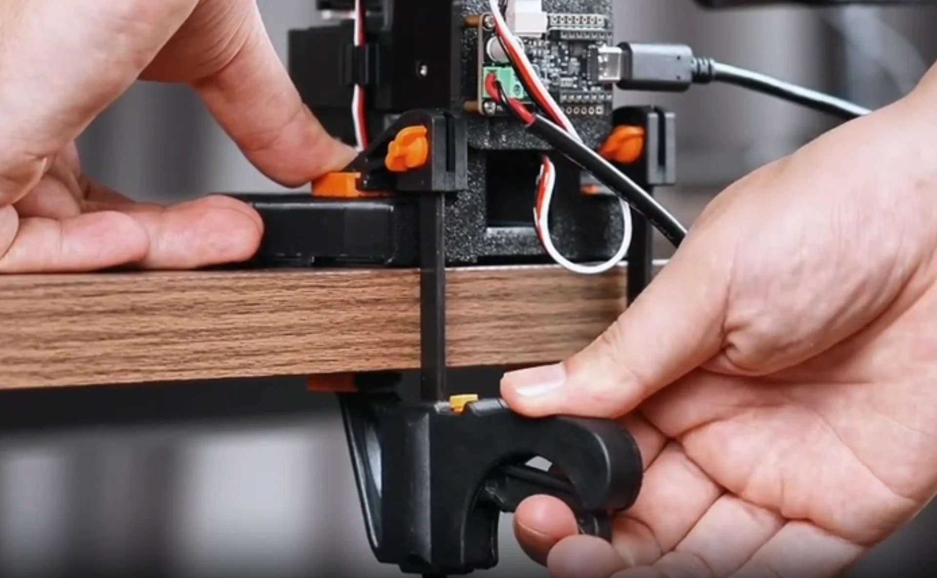
- Use the four kit clamps to secure the two arms, using two clamps per arm. Gently push each base to confirm that it cannot slide or tip over.
- Keep a safe distance between the arms and leave the full range of motion clear for every joint.
- With the power disconnected, move each joint slowly by hand to confirm smooth movement without collisions, binding, or contact with mechanical limits.
2.2 Install the control boards and connect USB-C
Step 2: Install the control boards
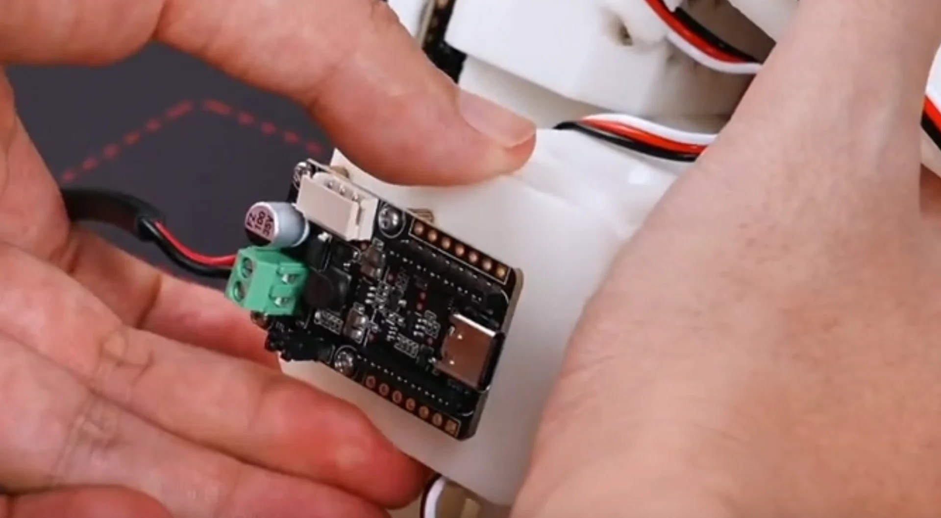
- Install one LeRobot servo control board on each arm. Align the board with the slot on the arm base, check the connector orientation, and install it securely. Do not force it in the reverse direction.
- Check that the cables between each control board and the servos are fully seated and are not loose, sharply bent, pinched, or connected to the wrong interface.
Step 3: Connect the data cables
The data connections are:
- Leader: SO-ARM101 Leader → USB-C data cable → computer
- Follower: SO-ARM101 Follower → USB-C data cable → computer
Use one USB-C cable to connect each control board to the computer. For easier serial-port identification, connect the arm ends first and connect the computer ends one at a time during the serial-port binding step in Section 3.2.2.
2.3 Install the power interfaces and power on
Step 4: Install the power interfaces
- Confirm that the power adapters are not connected to AC power.
- Insert each DC power adapter cable into the arm power interface and tighten the locking collar clockwise.
- Check the power requirements: Pro uses 5 V for the Leader and 12 V for the Follower; Standard uses 5 V for both arms. Do not mix the voltages.
- Confirm that each connector is locked and that the cables cannot enter the joint motion range.
Step 5: Power on
- Connect both power adapters to the outlet and turn them on.
- Observe the control-board indicators. If an indicator is off, flashes abnormally, becomes hot, or produces an odor, disconnect power immediately and inspect the system.
- USB-C is used for data communication only. Power and USB-C must both be connected during device scanning, calibration, and teleoperation.
3. Project workflow
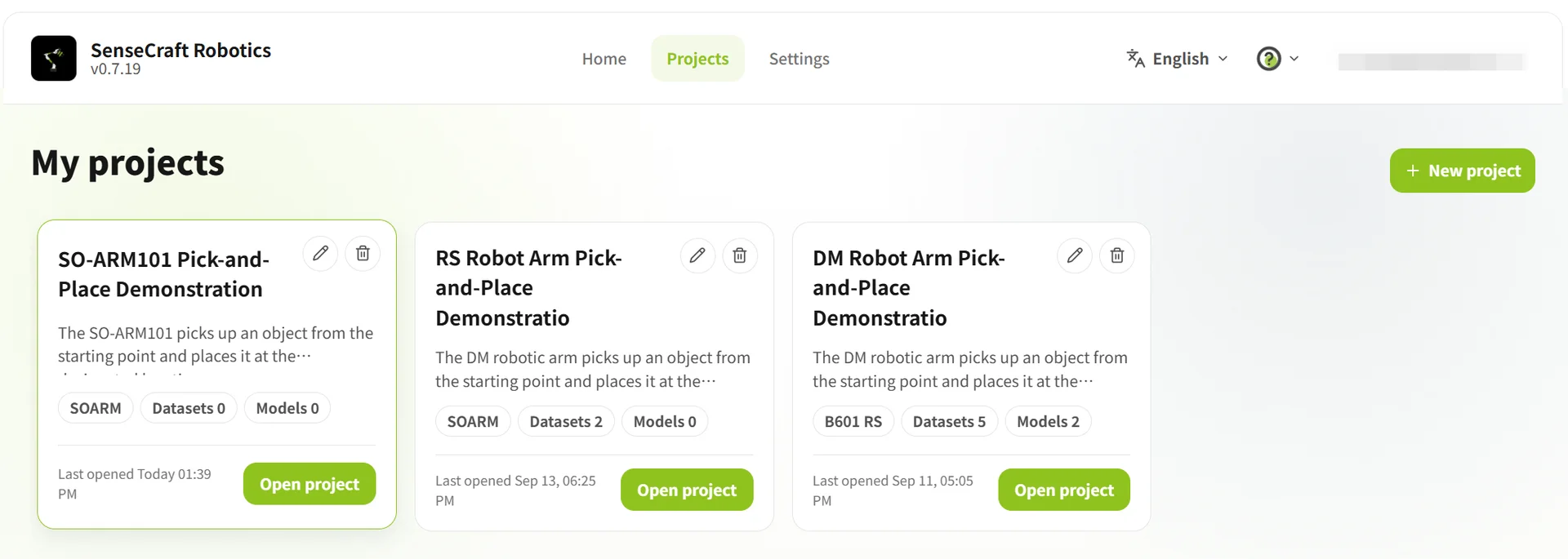
After signing in, open the Projects page. Create a project for first-time use or open an existing project. The project overview provides access to device setup, action replay, datasets, training, models, and operation.
| Operation | Steps |
|---|---|
| Create a project | Click New Project → enter the project name and description → click Create and Start |
| Open an existing project | Select a project from the project list → open it |
3.1 Project overview
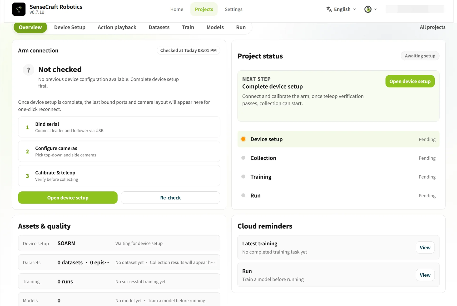
The Project Overview shows the current status of the arms, device setup, datasets, training, models, and operation.
If the page shows To be configured or Not connected, click Go to Device Setup to configure the arms.
3.2 Device setup
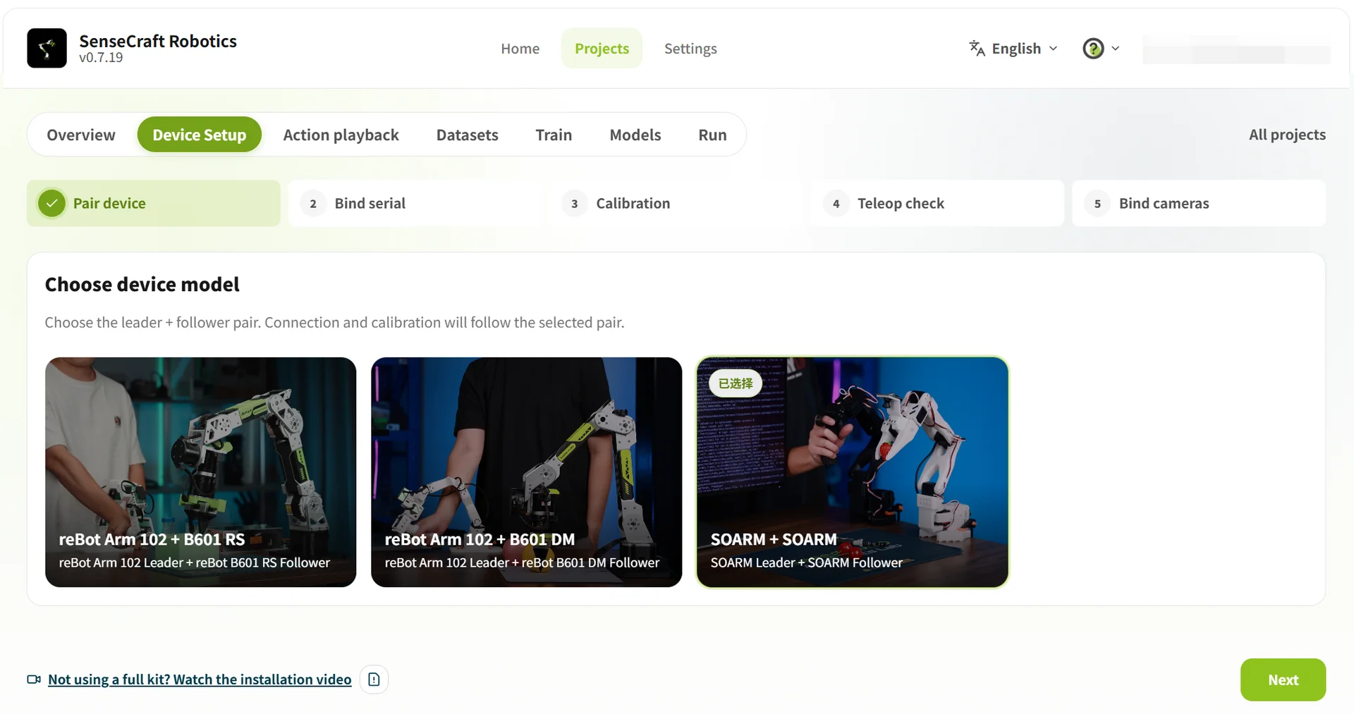
Device Setup is used for device selection, serial-port binding, arm calibration, teleoperation verification, and camera configuration.
3.2.1 Select the device model
In the Device Pairing step, select SO-ARM101 + SO-ARM101, then click Next to bind the serial ports.
3.2.2 Bind the USB serial ports
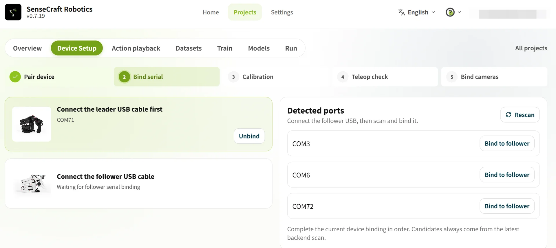
- Initial scan: Disconnect the USB cables from both arms, click Rescan, and note the ports currently shown.
- Bind the Leader: Connect the Leader SO-ARM101, click Rescan again, and bind the newly appearing port to the Leader.
- Bind the Follower: Connect the Follower SO-ARM101, click Rescan again, and bind the newly appearing port to the Follower.
- Confirm that both arms show Connected, then click Next.
Serial-port troubleshooting:
- After each scan, bind only the newly appearing port. Do not identify devices solely by their COM numbers.
- If a port is not shown, reconnect the USB cable and scan again. If only one port is shown, check the other USB cable and the device power.
3.2.3 Arm calibration verification
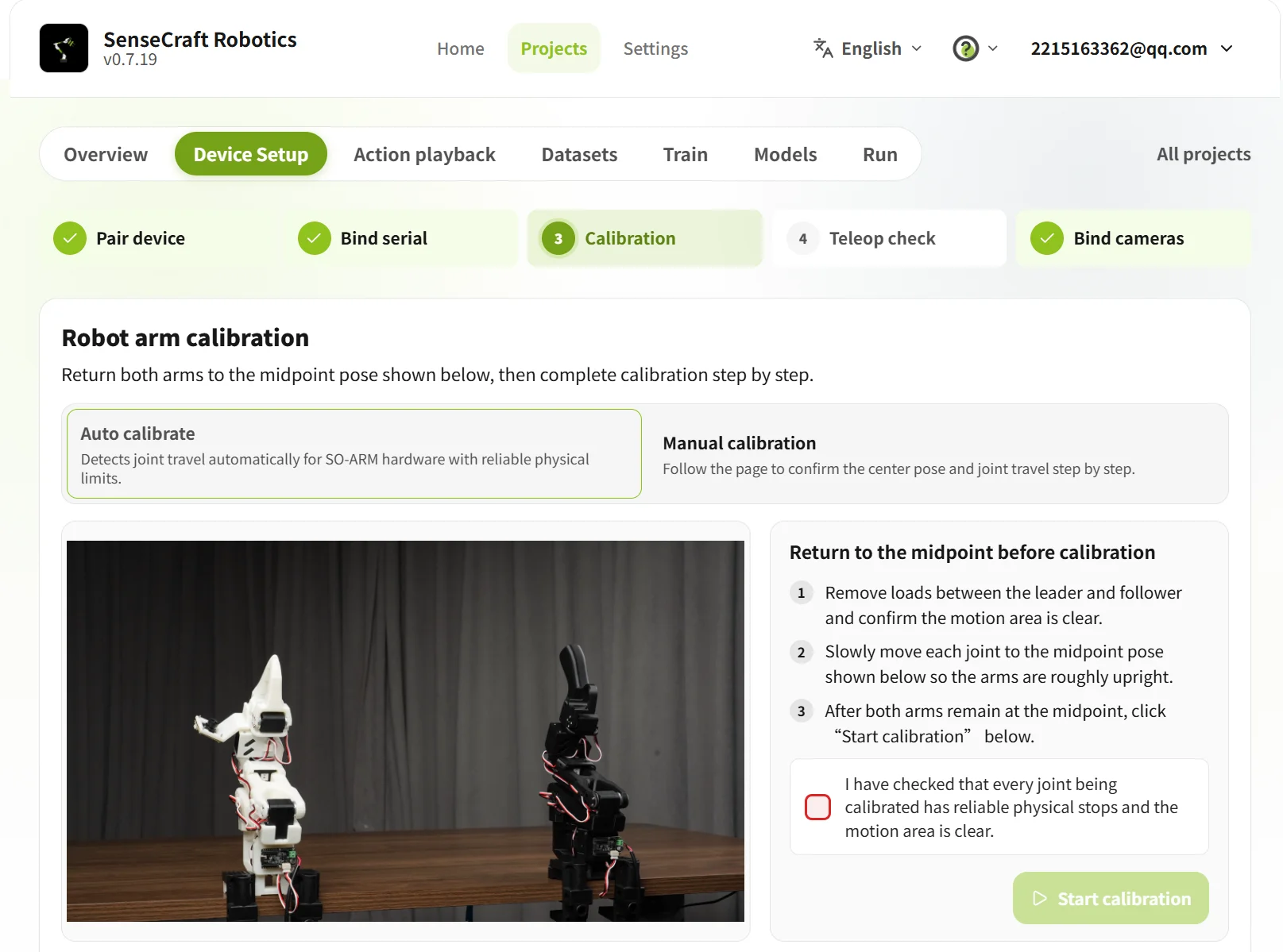
The calibration page provides Automatic Calibration and Manual Calibration. Before starting, move the Leader and Follower to the middle posture shown in the on-screen example and clear the arm workspace.
Automatic Calibration
Automatic Calibration automatically identifies the joint travel range. It is suitable for SO-ARM101 arms whose joints have reliable physical stops.
- Remove any load from the Leader and Follower, and confirm that there are no obstacles in the arm workspace.
- Follow the on-screen example and slowly move each joint in sequence so that the Leader and Follower are approximately vertical and aligned in the middle position.
- Confirm that all joints to be calibrated have reliable physical stops, then select the confirmation checkbox on the page.
- Click Start Calibration and wait for the system to identify the joint travel range and complete calibration.
Manual Calibration
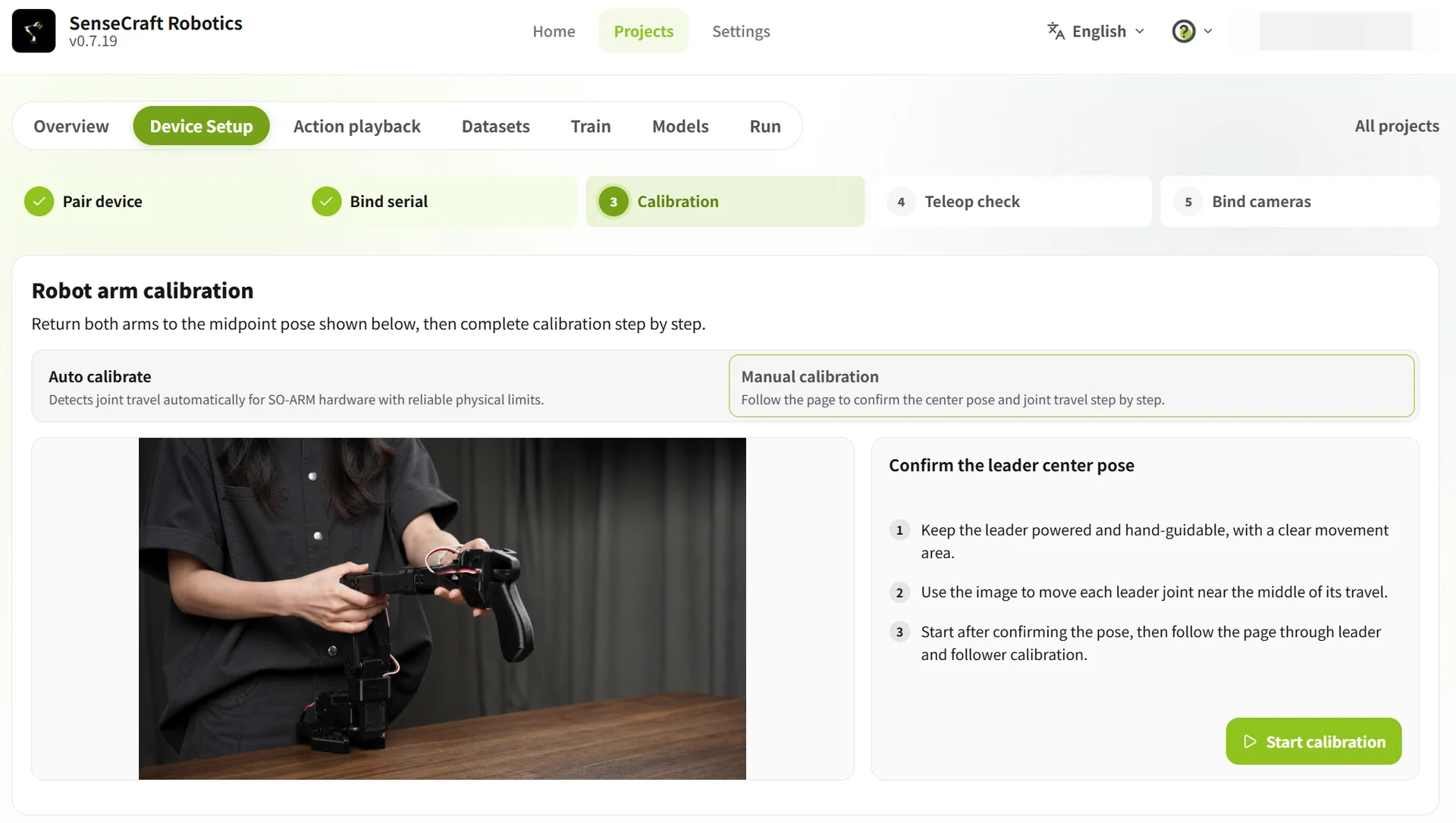
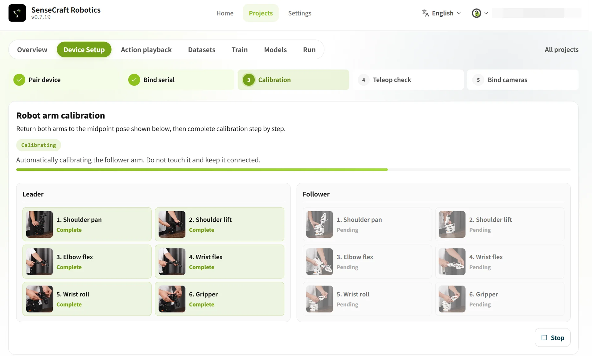
If a joint does not have a reliable physical stop, or if you need to confirm the middle position and joint travel step by step using the on-screen guidance, select Manual Calibration.
- Keep the Leader powered on and ready for manual guidance. Confirm that there are no obstacles in the arm workspace.
- Follow the on-screen example and slowly move each Leader joint close to the middle of its travel range.
- After confirming that the Leader posture is correct, click Start Calibration.
- Follow the on-screen instructions to confirm the middle positions and joint travel of the Leader and Follower in sequence.
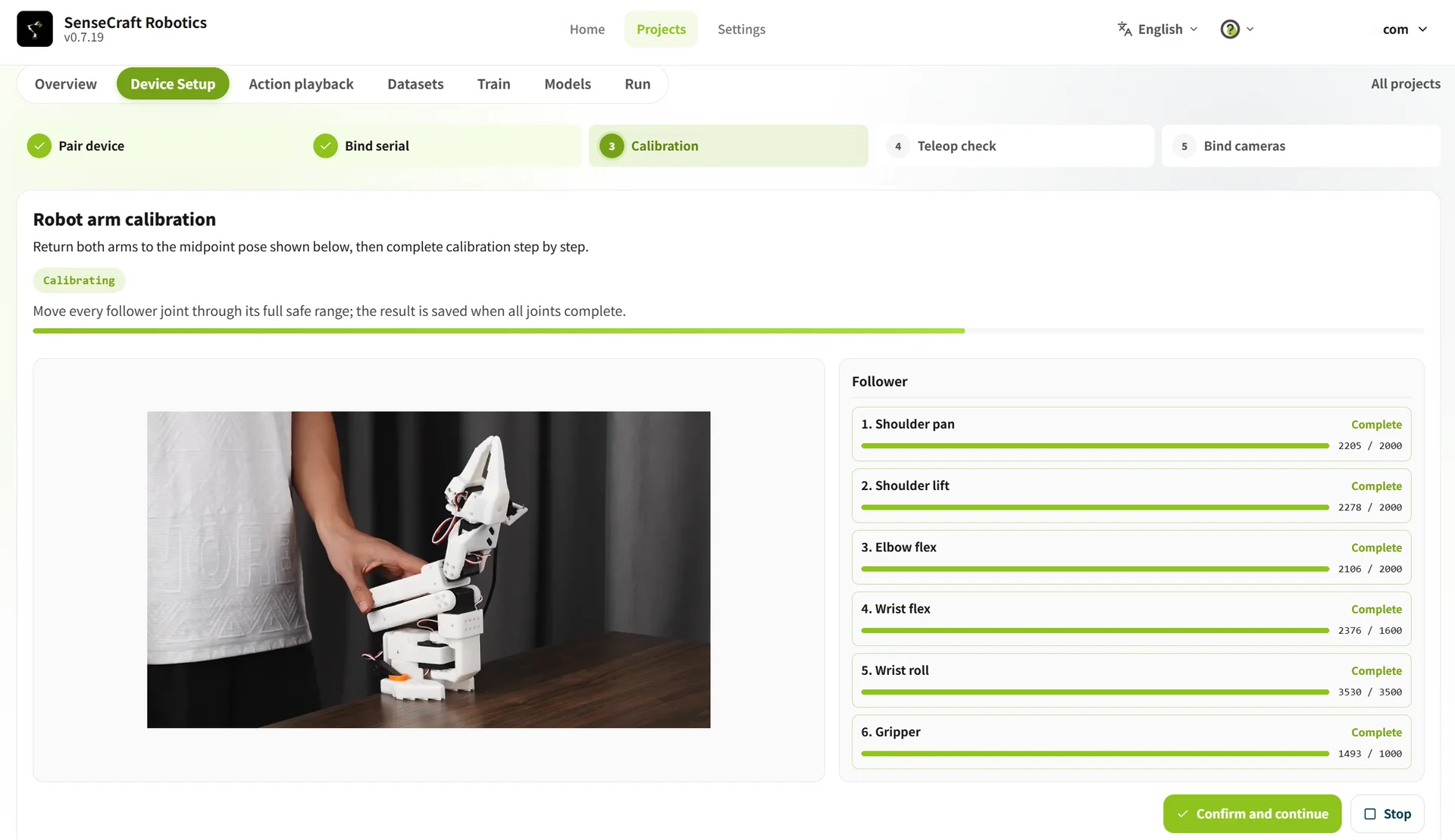
Do not perform teleoperation or data collection during calibration. If the arm posture is abnormal, a joint is obstructed, or calibration fails, stop calibration immediately, check the arm position and workspace, and try again.
3.2.4 Teleoperation verification
Teleoperation verification confirms that the Follower correctly follows the Leader. If the direction is reversed, the delay is excessive, or the movement is discontinuous, check the device roles, serial-port binding, and calibration result.
- Click Start Teleoperation.
- Move the Leader slightly and observe whether the Follower moves synchronously, follows the same direction, and moves smoothly.
- Click End Teleoperation after the check, then select the result:
- Normal: click Confirm Teleoperation Normal.
- Abnormal: click Abnormal, Return to Recalibrate.

Gravity compensation (optional) The arms have some weight, so manually adjusting the Follower may require effort. Gravity compensation offsets part of the weight and makes adjustment easier. Turn it off after adjustment and before teleoperation verification. Gravity compensation is for adjusting the Follower; it does not control the Follower to follow the Leader.
3.2.5 Bind the cameras
Two cameras and two views are required for data collection and model training. Depending on the mounting position, the common layouts are:
| Layout | Installation and purpose | Suitable scenarios | Illustration |
|---|---|---|---|
| Gripper view | Top-view camera: mounted above the front of the workbench to cover the work area. Gripper camera: mounted near the gripper to observe grasping details. | Fine operations that require observing contact between the gripper and the object. | 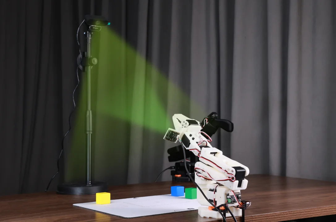 Note: You may design your own 3D camera mount. |
| Side-view assistance | Top-view camera: mounted above the front of the workbench to cover the work area. Side-view camera: mounted at the front side of the workbench to observe arm height and gripper motion. | Tasks such as grasping, handling, and placing. | 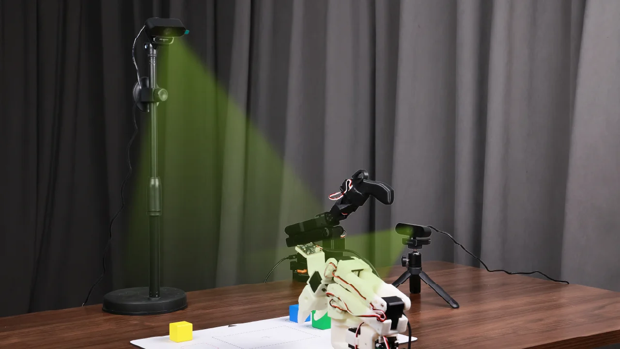 |
This tutorial uses the side-view assistance layout. Connect both cameras, install and position them, and then:
- Connect the cameras to the computer and click Rescan.
- Select the corresponding video streams in the Front Camera and Side Camera areas.
- Check both previews to confirm that the arms, object, and target position are clearly visible. Click Next after confirming.
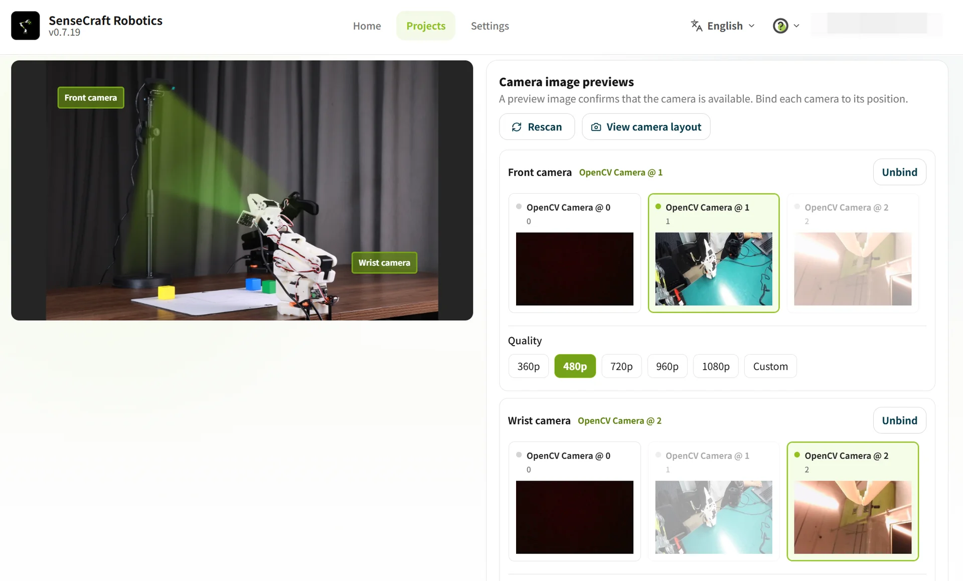
To confirm that each camera matches its mounting position, click View Camera Layout. If a preview is black or abnormal, rescan, restart the camera, or change the USB port.
3.3 Action replay
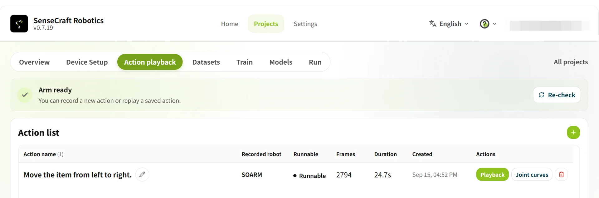
Action Replay records arm actions through Leader teaching and saves them in the action list for replay. After recording, check whether the action is continuous and whether the movement direction and gripper opening and closing are correct.
| Function | Operation | Purpose |
|---|---|---|
| Record an action | Click + to create an action → use the Leader to control the Follower → click Stop Recording to save | Record grasping, moving, and placing actions |
| Replay an action | Click Replay | Check that the action is complete and continuous, and that the movement direction and gripper action are correct |
Before recording an action for the first time, complete device setup and teleoperation verification, then click Confirm Teleoperation Normal. If replay is abnormal, delete the action and record it again.
3.4 Dataset
Dataset is used to create collection tasks and record, inspect, clean, and merge task episodes. A small-batch, multi-session approach is recommended so that disconnections, software problems, or video stutter can be found early.
- Record about 10 task episodes per batch first.
- After 2–3 batches, keep about 20–30 valid episodes for the first training run.
- Add more data for complex tasks according to the training results.
3.4.1 Configure a data-collection task
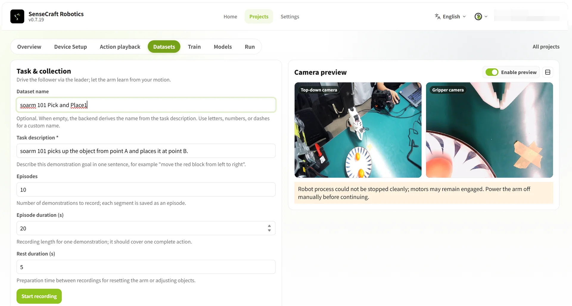
Open Dataset → Collect Data and enter the task information. If datasets will be merged, their task descriptions must be exactly the same. Keep the A/B positions, object category, camera positions, table background, and lighting as stable as possible.
| Field | Example | Guidance |
|---|---|---|
| Dataset name | SO-ARM101 pick-and-place A-to-B-01 | Use “device + task + batch” naming |
| Task description | Move the object from the left to the right | State the task goal clearly; descriptions must match exactly when merging |
| Number of episodes | 10 | Each episode completes one full task |
| Duration per episode | 20–30 seconds | Cover the complete action |
| Rest duration | 5 seconds | Reset the arms and the scene |
3.4.2 Record task episodes
Each episode should record the complete process of grasping the object at Point A, moving it to Point B, and releasing it. Keep the procedure consistent; add small changes in position, angle, and motion only when more generalization is required.
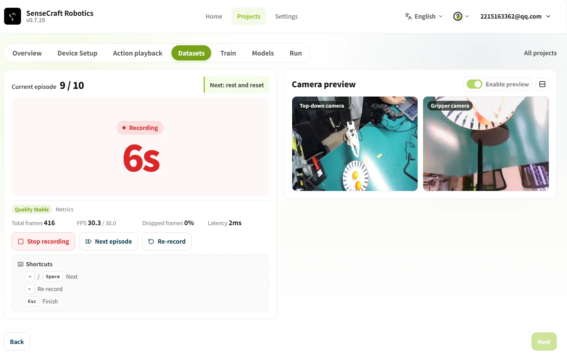
- Place the object at Point A, confirm the initial posture, and click Start Recording.
- Use the Leader to control the Follower through the task, then return the arm to the initial posture.
- After the task is complete, wait for the remaining time or click ➡ (or press Space) to end the episode early.
- During the rest period, return the object to Point A and prepare the arm for the next episode.
Important
- Secure the cameras before collection. The arms, gripper, object, and Points A and B must remain visible in both views.
- Do not allow key actions to be blocked or leave the camera views.
- If the task fails, the object is not held securely, the video stutters, or a camera is blocked, click Record Again or press
Escto stop collection.- You can finish the batch first and then inspect and delete abnormal episodes.
- Stop immediately if there is a loss-of-control or collision risk.
3.4.3 Inspect, delete, and merge data
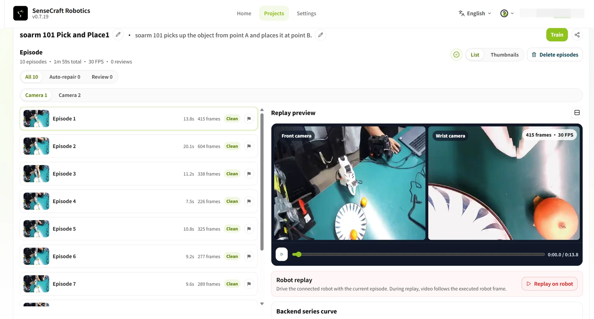
After collection, inspect abnormal episodes, delete invalid data, and merge compatible datasets when needed.
| Operation | Method | Description |
|---|---|---|
| Inspect abnormal episodes | Select an episode and play the video or action replay | Check task completion and gripper movement |
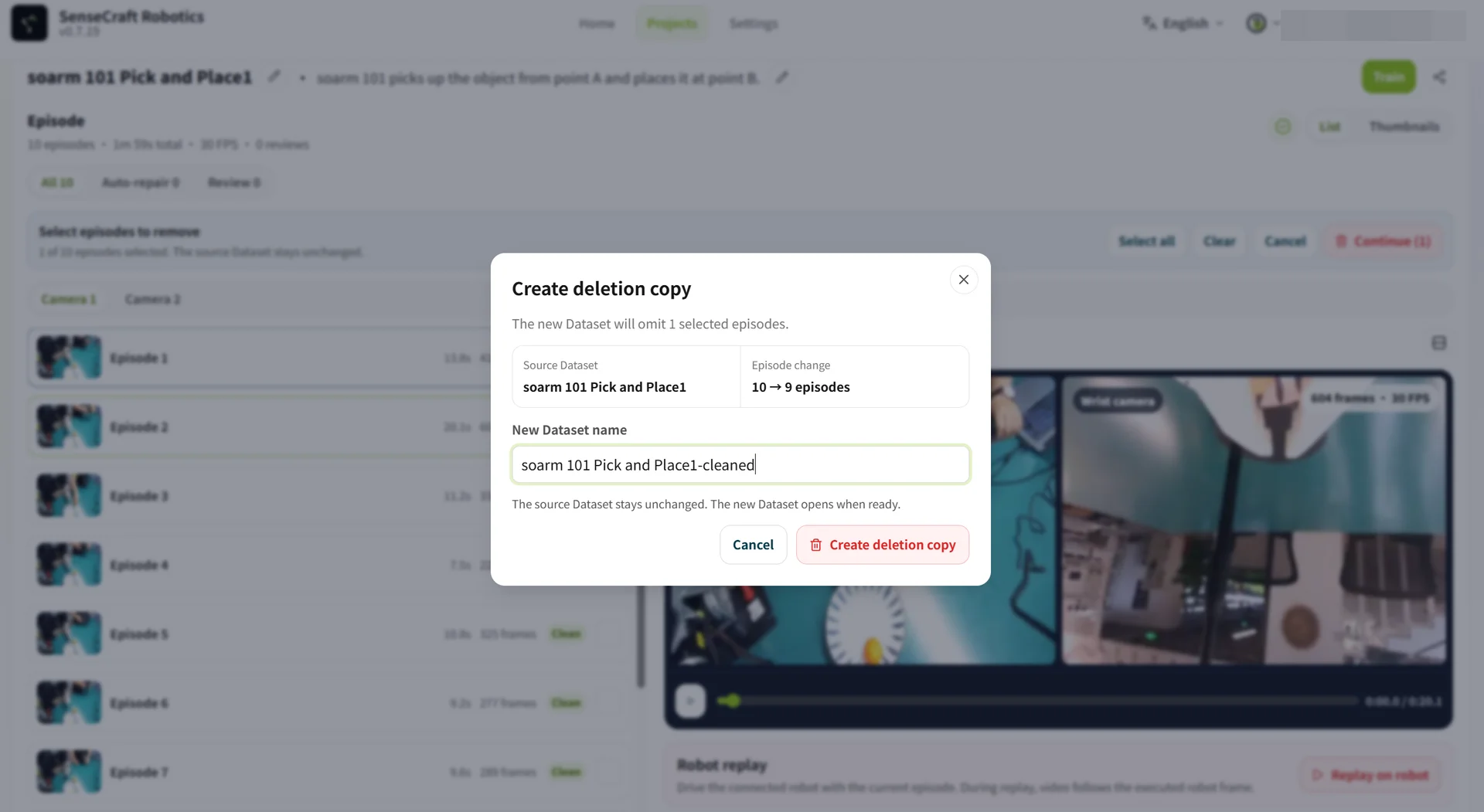
| Delete abnormal episodes | Click Batch Delete Episodes, select the episodes, confirm, and click Generate Deleted Copy | Rename the new dataset; the original dataset is not overwritten |
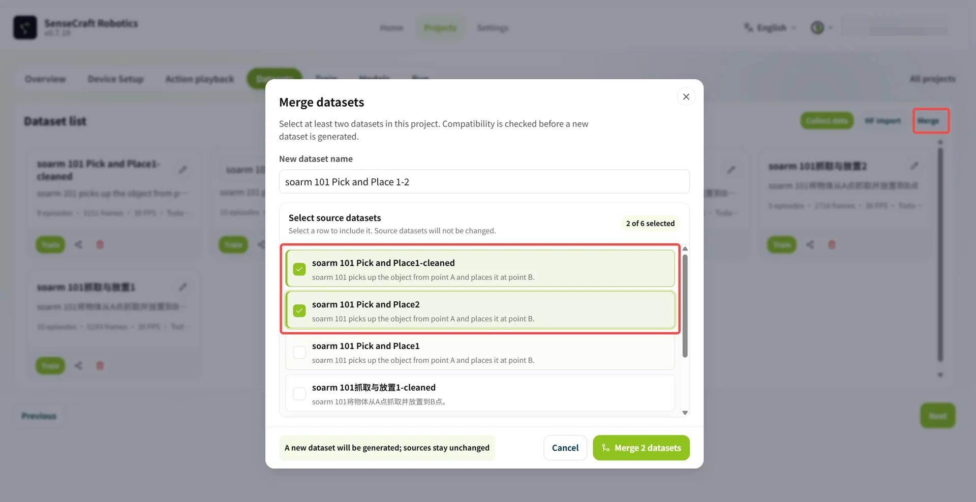
| Merge datasets | Click Merge, select datasets, and enter a new dataset name | Merge datasets with matching task descriptions, device combinations, and camera configurations |
3.5 Training
Training generates an action model from the teaching data. SenseCraft Robotics reads the recorded task data, analyzes how the arm performs the target action, and generates a model for autonomous operation.
| Parameter | Option / value | Details |
|---|---|---|
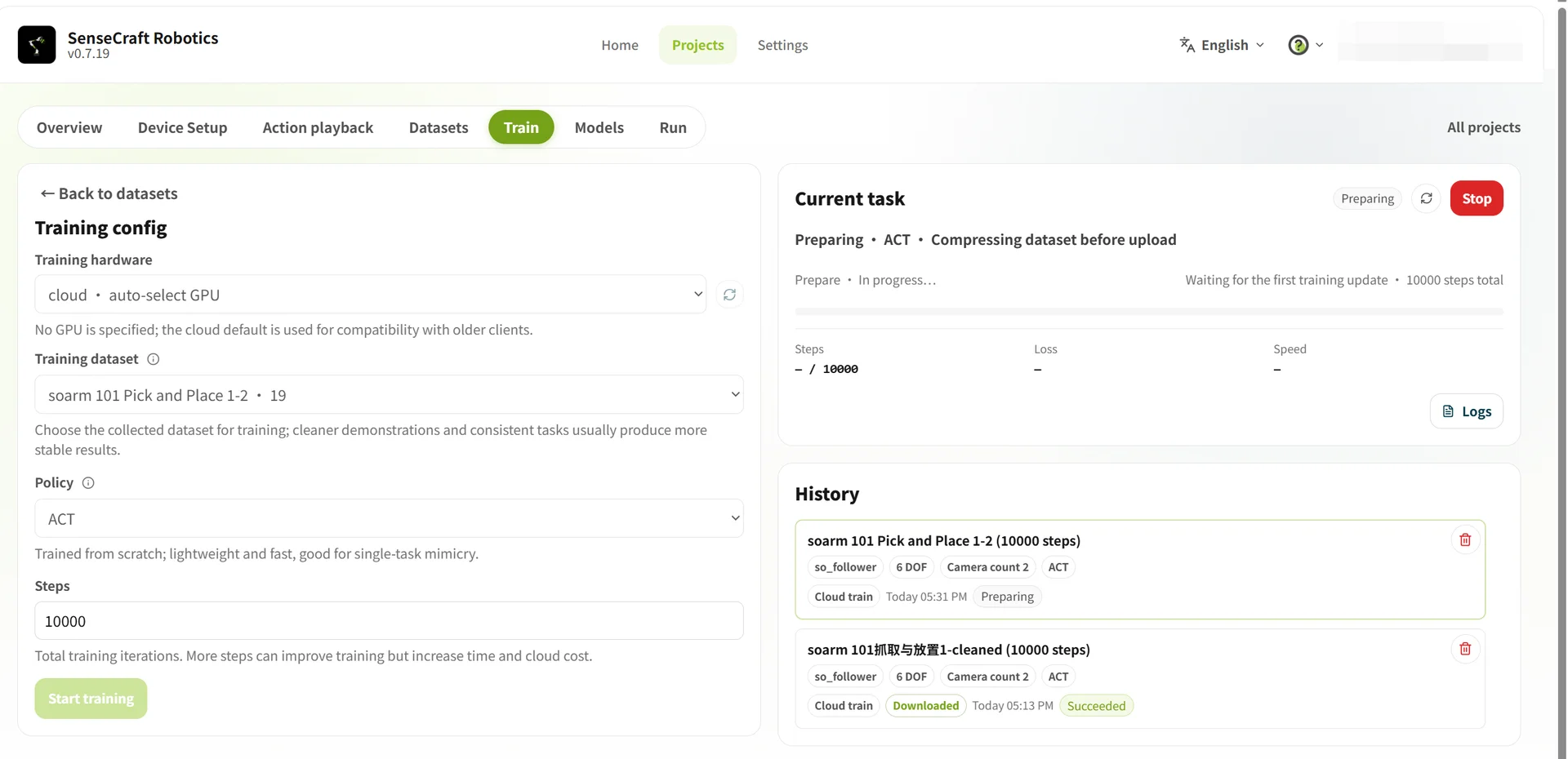
| Training hardware | Cloud · automatically select GPU | Uses a cloud server and consumes the corresponding credits. |
| Local · free | Uses the current computer and requires a compatible local GPU. | |
| Training dataset | Select the target dataset | Select a recorded and prepared dataset. |
| Policy | ACT | The current default action-control policy. |
| Training steps | 10000 | Recommended as the initial value; adjust it according to the results. |
Credits notice Cloud training consumes credits; local training does not consume cloud-training credits. Refer to Credit rules for credit information.
Recommended training steps and episode counts:
| Task difficulty | Task description | Recommended episodes | Recommended steps |
|---|---|---|---|
| Beginner | Fixed Point A to Point B | About 20 | 10,000–15,000 |
| Intermediate | Grasp and place at random positions | About 50 | 30,000–40,000 |
| Advanced | Multiple steps or long duration | About 100 | 80,000–100,000 |
Training duration: Total training time depends on the selected GPU model and the number of training steps. For example, 20,000 steps in the cloud may take from several minutes to dozens of minutes on most GPUs; 100,000 steps takes about five times as long.
Click Start Training after confirming the settings. View progress and history in Current Training Tasks.
3.6 Model
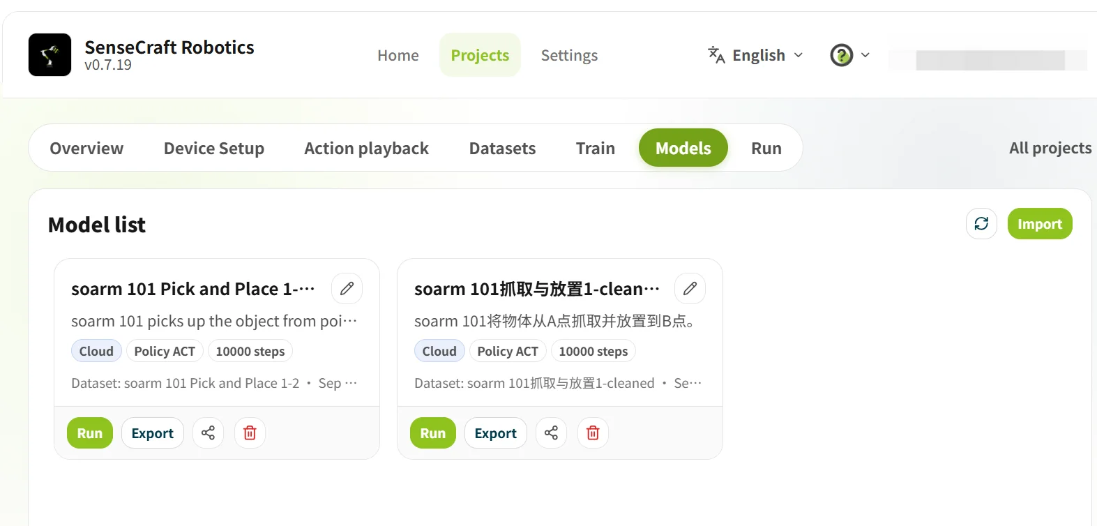
Model is used to view training results and select a model for operation. Confirm that training is complete and that the task and device combination match the current project.
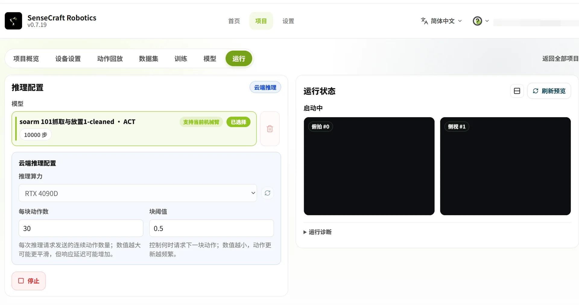
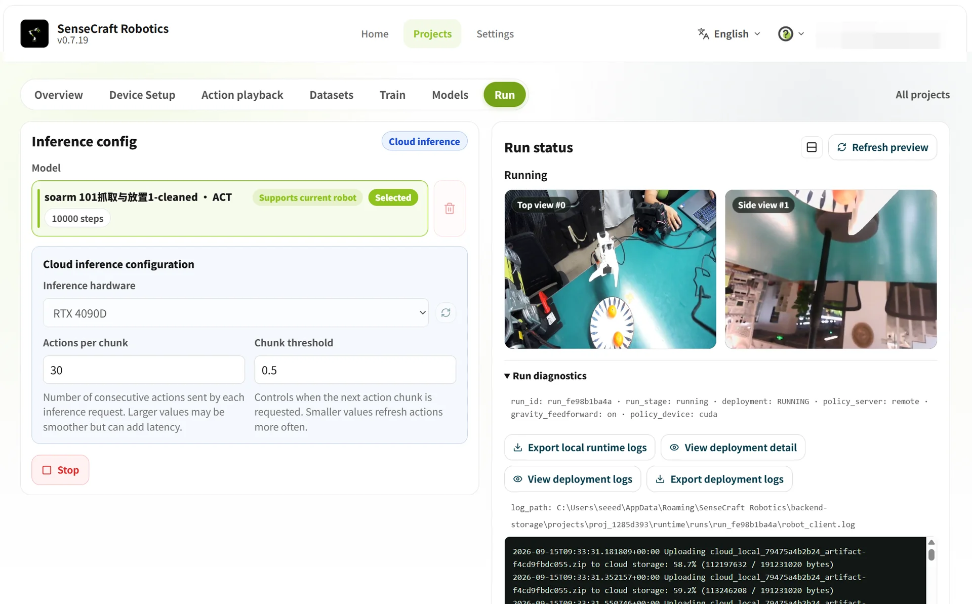
3.7 Operation
Operation loads a trained model onto the arms to verify whether it can complete the task correctly.
- Select a model: Select a model marked as supporting the current arms.
- Select an inference method: Select Cloud Inference or Local Inference and configure the corresponding parameters.
- Start inference: Confirm the settings and click Start Cloud/Local Inference.
Key differences between cloud inference and local inference:
| Comparison | Cloud inference | Local inference |
|---|---|---|
| Computing hardware | Uses a high-performance cloud GPU. | Uses the local CPU; the current platform does not support a local GPU. |
| Performance impact | Results depend heavily on network transmission quality. | Results depend on local CPU performance. |
| Parameters | Action count (default 120): predicted action steps per inference. Chunk threshold (default 0.9): affects smoothness and accuracy. Higher values are more cautious and may pause; lower values are smoother but may increase errors. | Run count: number of repeated task runs. Time limit per run: maximum duration of one run; it ends automatically on timeout. |
| Data output | Performs inference verification only. | Automatically generates a dataset from the inference runs after operation ends. |
| Cost and limitations | Subject to platform rules; computing power is suitable for getting started quickly. | Usually does not require cloud credits, but is limited by local CPU performance. |
Notes
- Before operation, confirm that the arms are connected correctly and that the workspace is safe.
- During operation, do not disconnect or disassemble the arms. Observe their movements.
- If the result is unsatisfactory, return to Dataset, delete abnormal episodes, add valid data, and train again.