Edge Assembly Inspection: Missing Parts, Dimensions, Modbus and MQTT
Dimension results are pixels converted through a calibration reference and do not replace a calibrated gauge in an acceptance test. The shipped detector is trained on DeepPCB, a bare-board defect dataset whose six classes are not assembly missing parts; before using it on your product, replace the expected-item list with your own and measure on your own data.
What this solution does
One fixed camera watches one inspection station. Each frame goes through a detector, then through missing-part comparison and dimension measurement, and ends as one OK/NG verdict at line takt.
- Missing-part comparison — a template expected-item list (
class+ ROI + match distance) is matched against the detections. Whatever the list expects and the frame does not contain becomesmissing; anything found outside the list can optionally be reported asextra. - Dimension measurement — a calibration reference in the plane of the measured surface gives
mm_per_pixel; the minimum-area rectangle of the target inside a measurement ROI is converted to millimetres and compared against nominal ± tolerance. - Verdict merge —
defect,missing,extraanddimension_out_of_toleranceeach make the frame NG on their own; each of the four can be switched off.
The verdict is written to two places: Modbus TCP holding registers and coils for the PLC, and one MQTT JSON event per frame for the MES or historian. Registers are written before the coil, so a PLC that acts on the coil reads register data from the same verdict.
- Packaging source and deployment guide: sensecraft-solutions / solutions/edge_inspection_assembly
- Picking a configuration and deploying: reference design page
Ready to run on the device
Install the application package on a reComputer J30 / J40 series or R2000 series and it runs; a first install takes about 60 minutes. Measured capture-to-coil P50 on the J40 series: 10.92 ms.
Open source
Runtime code is Apache-2.0; the detector is YOLOX-Tiny (Apache-2.0), with no Ultralytics code or weights and no AGPL obligation.
Your own cameras, PLC and MES
Any RTSP / ONVIF / USB camera; verdicts go out over Modbus TCP and MQTT. HR 0–7 use the same register layout as the surface inspection design, so an existing PLC program needs no change.
Runs entirely on site
Capture, inference, verdict and output all run on the inspection host; the main chain needs no internet access.
What the demo actually shows
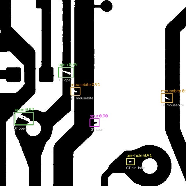
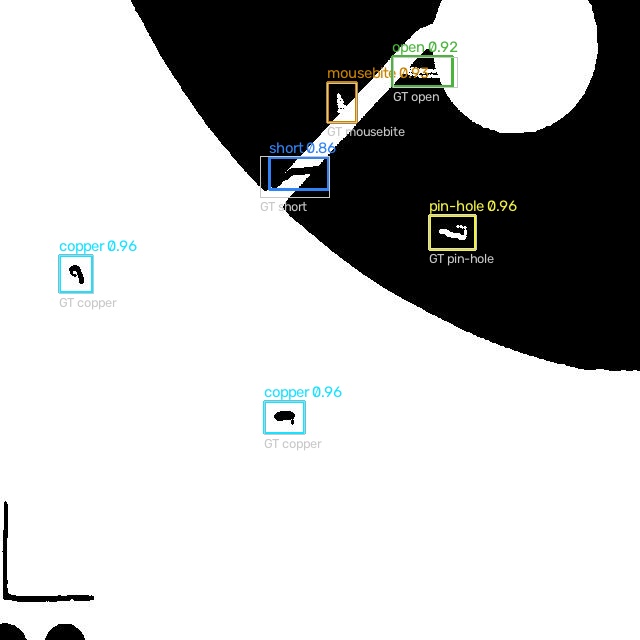
The images below are real outputs of the pipeline:
- The detector's output on one DeepPCB validation image (
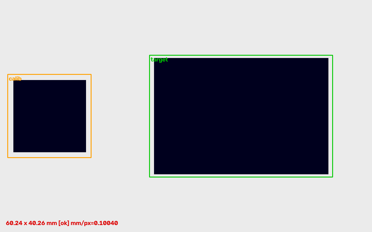
12300060_test.jpg); every box is a detection from the ONNX model. The six-item expected list in the shipped example configuration was generated from this frame's ground-truth boxes. - A synthetic ArUco dimension scene at nominal size: the marker on the left gives mm/px, the block on the right is measured against it (60 × 40 mm, verdict OK).
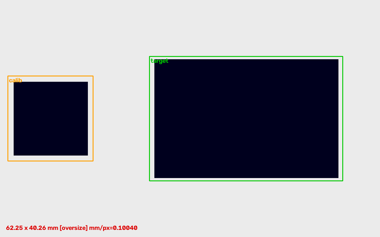
- The same scene with an oversize part: 62.25 mm against a 60 mm nominal and 1 mm tolerance, verdict NG, Modbus HR 10 = 6225 and HR 11 = 2.
The detector's output on DeepPCB validation images:
The dimension chain: the marker on the left gives mm/px, the block on the right is measured against it. At nominal size the verdict is OK:
An oversize part in the same scene measures 62.25 mm, verdict NG, Modbus HR 10 = 6225 and HR 11 = 2:
With the part rotated 25°, the minimum-area rectangle gives the same size:
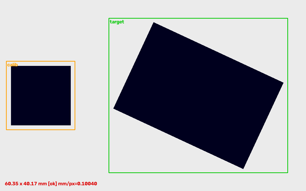
The dimension scenes are generated by evaluation/make_dimension_fixture.py at a known mm/px; ground truth comes from the generation parameters. They are not photographs of a real station.
What hardware you need
Three things per station: a camera, an inspection host, and a system that receives the verdict.
① Camera — any RTSP or ONVIF camera; a USB camera or a recorded file also works. Any model will do, as long as the whole board or assembly is in frame and the framing does not change after the template is built.
② Inspection host — decides how many stations one host can carry.
| Inspection host | Accelerator | Detector as deployed | Measured streams | When to choose it | |
|---|---|---|---|---|---|
 | reComputer J3011 (Jetson Orin Nano 8GB) Single-station host | Orin GPU | YOLOX-Tiny 640², TensorRT FP16 | 1 stream, 67 h soak | A single station |
 | reComputer J4012 (Jetson Orin NX 16GB) Multi-station aggregation host | Orin GPU | YOLOX-Tiny 640², TensorRT FP16 | 8 stable / 12 degrading / 24 failing | Several stations on one host; the accuracy and speed data were measured on this module |
Stream capacity: 640² at 10 fps per stream, five minutes per level, the whole sweep run twice, with MQTT and Modbus disabled. With both outputs enabled the reachable count is below 8.
Both reComputer models come in a fanless industrial enclosure (reComputer Industrial J3011 / J4012) with the same module and runtime, for in-cabinet mounting.
③ Everything else — for the dimension check, a calibration reference in the plane of the measured surface (an ArUco marker, DICT_4X4_50 by default, or any object of known width); Ethernet between camera and host; and a Modbus TCP master (the PLC) and/or an MQTT consumer. The main chain needs no internet access.
Negative Selection Boundaries
- Single vs Multi-Station: J3011 is sized for single-camera inspection per station. If one host must monitor multiple stations (>2 cameras concurrently) or high frame rates, choose J4012.
- Dynamic Model Updates: Hailo-8 requires offline model compilation. If your workflow requires frequent on-device tuning or direct PyTorch/ONNX execution, choose the Jetson series.
How to deploy on site
Fix the camera and optics first, then install the software.
One: install the hardware, camera first
Expected-item ROIs are stored as picture coordinates. After the camera is moved, remounted or refocused, the whole assembly.expected[] template must be rebuilt. Any camera work on the line means re-templating that station.
The whole board or assembly must be in frame. For the dimension check, put the calibration reference in the same plane as the measured surface; a different working distance becomes measurement error and raises no error message. Without a reference, the dimension section reports uncalibrated, Modbus HR 11 = 4, and no value.
Two: install the software
The per-device steps are on the reference design page, where picking a configuration for your site also gives you the matching application package to download.
Both paths follow the same steps:
- Pick a preset and a host.
Camera + reComputer J30 / J40 (Orin)orCamera + reComputer R2000 series (Hailo-8). Rated advanced; allow about 60 minutes for a first install. - Deploy the inspection runtime (required). On Orin the TensorRT engine is built on the device at first deploy, about 5 minutes, and is tied to that device and TensorRT version. On Hailo the INT8 HEF is compiled off-device and downloaded at deploy time, with no build on the board, but three prerequisites apply: a matching Python minor version; HailoRT 4.21.x at the same version across driver, user library and Python bindings; and the kernel parameter
hailo_pci force_desc_page_size=4096. - Set up dimension calibration (optional). Without it the missing-part chain still runs and the dimension section reports
enabled: falseoruncalibrated. - Check the verdicts (optional). The local web panel on port 8080 shows health counters, recent events and an MJPEG preview with detection boxes and assembly ROIs. Confirm here that the camera covers the right area before wiring the PLC.
- Generate the expected list with the SAM2 annotation tool (optional). The tool runs on an offline workstation, not on the edge device, and stays out of the frame loop: a person draws the box, SAM 2.1 Hiera-Small turns it into a pixel mask, and the mask is expanded into an assembly ROI. A numpy Otsu-flood backend that needs no GPU is also included.
Before going live, replace assembly.expected[] with your own slots. The shipped list was generated from one DeepPCB image and only serves to exercise the chain.
What interfaces are available
Data leaves the inspection host on three interfaces, all served locally by the host.
- A PLC that already acts on an OK/NG coil — read Modbus TCP on port 502, unit 1. HR 0–7 match the layout of surface inspection contract v1, so an existing program keeps working; the new information is in HR 8–11.
- A MES or historian — subscribe to
<device-name>/inspection/<stream-id>/resultson port 1883. One JSON event per processed frame, schema2.0.0, validated against the contract before publishing. - An operator or commissioning engineer — the HTTP panel on port 8080.
<device-name> is set at deploy time and forms the first topic segment; name it by line, cell or station so several hosts on one broker stay separate. The stream id is also written in the payload, so downstream code does not need to parse the topic.
Full interface table
| Type | Where | Content | Notes |
|---|---|---|---|
mqtt | 1883, <device-name>/inspection/<stream-id>/results | verdict, verdict_reasons, defect_count, detections[], assembly (enabled, expected_count, matched_count, missing_count, extra_count, each missing item with its label and ROI), dimension (enabled, calibrated, mm_per_pixel, out_of_tolerance_count, measurements[] with per-measurement status) | Schema 2.0.0; both sections always present, enabled: false when the module is off for that source |
modbus_tcp | 502, unit 1, Coil 0/1 + HR 0–11 | Coil 0 = NG, Coil 1 = OK (mutually exclusive). HR 0–7 as contract v1: primary class, defect count, bbox ×10000, heartbeat. HR 8 = missing count, HR 9 = extra count, HR 10 = measured mm ×100, HR 11 = tolerance code | Registers written before the coil flips, under one lock |
http | 8080, /healthz /events /preview.mjpg | fps, inference time, missing and dimension failure counters; the most recent events; MJPEG preview with boxes and ROIs | Local panel, no auth |
HR 11 tolerance code: 0 ok, 1 undersize, 2 oversize, 3 not_found, 4 uncalibrated.
verdict_reasons is a list; the four reasons (defect, missing, extra, dimension_out_of_tolerance) can appear together. ROIs are configured per source (sources[].assembly and sources[].dimension). An assembly section generated by the annotation tool carries roi_profile_sha256, identifying which ROI profile runs on site; with hand-written ROIs it is omitted or null.
{
  "schema": "2.0.0",
  "device": "assembly-station-01",
  "stream": "cam_pcb_top",
  "timestamp": 1729000000.456,
  "verdict": "NG",
  "verdict_reasons": ["missing"],
  "defect_count": 0,
  "detections": [],
  "assembly": {
    "enabled": true,
    "expected_count": 6,
    "matched_count": 5,
    "missing_count": 1,
    "extra_count": 0,
    "missing_items": [
      {"label": "capacitor_c12", "roi": [120, 240, 160, 280]}
    ]
  },
  "dimension": {
    "enabled": true,
    "calibrated": true,
    "mm_per_pixel": 0.125,
    "out_of_tolerance_count": 0,
    "measurements": [
      {"name": "pcb_width", "value_mm": 60.05, "status": "ok"}
    ]
  }
}
Three things to watch when reading fields:
- When
HR 10 = 0, read HR 11 first.3and4mean there is no measurement, not a 0 mm reading. - In v2,
verdict = NGcan come withdefect_count = 0. A missing part or an out-of-tolerance measurement also makes the frame NG. - Coil and registers are one sample only on the write side. Reading them as two Modbus requests can straddle two verdicts at high verdict rates, observed at about 20 verdicts/s. If it matters, poll the registers first and use the coil as the trigger.
With several streams on one host, the Modbus registers hold the latest verdict from whichever stream produced it; per-stream results come from MQTT. The packaged MQTT broker is local and anonymous; point a production install at a broker with credentials.
Performance and measured data
Speed and latency
"Detector throughput" covers the detection call only; "full pipeline" adds the verdict merge, Modbus, MQTT and contract validation, unthrottled; "end-to-end" is capture to Modbus coil write, throttled to a 10 fps line rate.
| Device | Model / precision | Detector throughput | Full pipeline | End-to-end capture → Modbus coil |
|---|---|---|---|---|
| reComputer J40 series (J4012, Orin NX 16GB) | YOLOX-Tiny 640², TensorRT FP16 | 95.06 FPS (detect() P50 10.52 ms) | 89 FPS (P50 42.9 ms) | P50 10.92 ms / P99 11.18 ms; 3000 samples, 0 dropped. After a from-scratch deployment (engine built on the device): P50 9.81 ms / P95 10.18 ms, n=300 |
| reComputer R2000 series + Hailo-8 | YOLOX-Tiny 640², HailoRT INT8 HEF | Hardware 106.75 FPS (hailortcli run); application 94.02 FPS (P50 10.64 ms) | 43.92 FPS | P50 11.89 ms / P99 16.08 ms |
Conditions: Orin detector figures timed over 500 runs on 60 pre-decoded frames; engine execute is about 6.3 ms of that, the rest is letterbox plus CPU NMS. Stream capacity measured on reComputer J40 series (J4012): 8 stable / 12 degrading / 24 failing; 640² at 10 fps per stream, five minutes per level, the whole sweep run twice, MQTT and Modbus disabled. reComputer J30 series (J3011) ran one 10 fps stream continuously for 67 h, end-to-end P50 11.45 ms.
Reproduce: solutions/edge_inspection_assembly/evaluation/ (Hailo-8: evaluation/runs/2026-09-06-rpi-hailo/results.md)
Detection accuracy
| Metric | Value | Conditions |
|---|---|---|
| mAP50, reComputer J40 series, TensorRT FP16 | 0.9876 | DeepPCB6 val, 205 images / 1158 boxes / 6 classes; at threshold 0.35, P 0.9284 / R 0.9741, FP 87 / FN 30, 0 fully missed frames |
| mAP50-95, reComputer J40 series (deployed from scratch) | 0.8207 | Same val set; CPU reference 0.8213 |
| mAP50, reComputer R2000 series + Hailo-8, INT8 HEF | 0.9858 | Same val set; −0.0018 against the CPU reference |
| mAP50, Hailo Dataflow Compiler emulator, INT8 | 0.9924 | 20 val images / 118 boxes, not directly comparable with the 205-image rows; CPU, native and quantized give the same mAP50 / P / R, per-box CPU ↔ quantized 119/120 matched |
Dataset: DeepPCB (MIT), six classes (open / short / mousebite / spur / copper / pin-hole), not redistributed with the package.
Reproduce: solutions/edge_inspection_assembly/evaluation/ (emulator: evaluation/runs/2026-09-05-m3-hef/)
Missing parts and dimensions
| Item | Result | Conditions |
|---|---|---|
| Missing-part ground-truth loop | Template frame 6 / 6 matched; after swapping boards 6 / 6 reported missing | Expected list built from one val image's ground-truth boxes (ROI = GT box × 1.6, 6 entries); after the swap verdict_reasons lists missing alongside defect |
| Dimension error (ArUco calibration) | Worst relative error 0.65%, budget 1% | Synthetic ArUco scene, no lens or lighting error; long side 60 → 60.241 mm (+0.40%), short side 40 → 40.261 mm (+0.65%); tolerance ±1.0 mm, verdict ok; uncompressed PNG and mp4v give identical values |
| Single-stream soak | 67 h continuous run, 0 dropped frames | reComputer J30 series (J3011), single stream at 10 fps; starting baseline RSS 256–259 MiB, junction temperature 61–62 °C, 0 restarts |
Reproduce: evaluation/make_dimension_fixture.py, evaluation/smoke_cpu_dimension.py; soak tiers in boundary.soak.yaml
Runtimes and key parameters
| Device | Model | Precision | Runtime | How the model reaches the device |
|---|---|---|---|---|
| reComputer J30 / J40 series | YOLOX-Tiny 640² | FP16 | TensorRT | Engine built on the device at first deploy (about 5 minutes), tied to that device and TensorRT version |
| reComputer R2000 series + Hailo-8 | YOLOX-Tiny 640² | INT8 | HailoRT 4.21.x | HEF compiled off-device with the Hailo Dataflow Compiler (optimization level 1 + Bias Correction), downloaded at deploy time |
- Detection threshold:
0.35(evaluation config) - Calibration target: ArUco
DICT_4X4_50(default), or any reference object of known width - Verdict reasons:
defect/missing/extra/dimension_out_of_tolerancecan be switched off one by one;extrarequires extra-part reporting to be enabled
Known degradation
- Moving, remounting or refocusing the camera invalidates the ROI template; rebuild the expected list.
- A calibration target at a different working distance from the measured face, a tilted part or low edge contrast produce dimension error,
not_foundoruncalibrated, with no error raised. - Accuracy comes from DeepPCB bare-board defects: synthetic defects with clean edges, and the six classes are not missing assembly parts. Real assembly scenes are harder.
- On the reComputer R2000 series the bottleneck is the host CPU: the full pipeline runs at 43.92 FPS and falls further below detector throughput than on Orin.
- Stream capacity was measured with MQTT and Modbus disabled; with both outputs enabled the reachable count is below 8.
Data and asset sources
- DeepPCB — github.com/tangsanli5201/DeepPCB, MIT licence. Used to train the shipped detector and as the val set for every accuracy figure above. The MIT licence permits redistribution and commercial use and requires the copyright notice to travel with copies and derivative works; the attribution travels with the images in the package's
gallery/ATTRIBUTION.md. The images are binarised greyscale scans of bare PCB copper layers, with no people and no customer-identifying content. The dataset is not redistributed with the package. - YOLOX — github.com/Megvii-BaseDetection/YOLOX, Apache-2.0. Detector backbone. No Ultralytics code or weights are used, so there is no AGPL obligation.
- SAM 2.1 Hiera-Small — github.com/facebookresearch/sam2, Apache-2.0 code and checkpoints. Used only by the offline annotation tool.
- Dimension fixture images — synthetic, generated by this project's
evaluation/make_dimension_fixture.py. No third-party material, no attribution required. - Architecture diagram — drawn from the package's device catalogue and output interfaces.
The runtime code is Apache-2.0. The shipped model is trained on DeepPCB; see the usage notice at the top for its scope.