StackForce Giant Bipedal Wheeled Robot Development Guide
This guide is designed for professional developers and researchers, providing a complete solution from basic setup to advanced application development. If you are a beginner, we recommend starting with the Mini version.
📋 Table of Contents
- Product Overview
- BOM Bill of Materials
- Core Features
- Quick Start
- Remote Control Operation Guide
- System Debugging Guide
- Hardware Assembly
Product Overview
Product Positioning
The StackForce Giant Bipedal Wheeled Robot is a professional-grade wheel-legged robot system built on the StackForce lightweight robot development platform. Compared to the Mini version, the full version has significant improvements in hardware configuration, software functionality, and expansion capabilities, specifically designed for professional development, academic research, and commercial applications.
Core Technical Architecture
Dual-Chip Collaborative Control System
- S1 Main Control Chip: Responsible for motor control, FOC algorithm execution, and motion control
- S3 Coprocessor Chip: Responsible for servo control, sensor fusion, and wireless communication
Omnidirectional Kinematics Model
- Quaternion-based attitude calculation algorithm
- Real-time inverse kinematics solution
Intelligent Balance Algorithm
- Adaptive PID control
- Dynamic center of gravity adjustment
- Complex terrain adaptive stabilization
BOM Bill of Materials
Large Wheel-Leg Structure Bill of Materials
| Item Name | Quantity | Notes |
|---|---|---|
| Electronic Components | ||
| StackForce Main Control Board | 1 | |
| StackForce High Current Board A | 1 | |
| StackForce High Current Board B | 1 | |
| StackForce Servo Board | 1 | |
| StackForce CAN Board | 1 | |
| StackForce IO Expansion Board | 1 | |
| StackForce Hall Board | 1 | |
| Carbon Fiber Structural Parts | ||
| Side Panel | 2 | 5mm thickness |
| Side Panel Base Frame | 2 | 3mm thickness |
| Front Guide | 4 | 5mm thickness |
| Baffle | 2 | 3mm thickness |
| PLA 3D Printed Parts | ||
| Upper Leg | 4 | |
| Lower Leg | 4 | |
| Front/Rear Panel | 4 | |
| Front/Rear Panel Connector | 4 | |
| Baffle Connector | 4 | |
| Main Control Base | 1 | |
| Motor Cover | 4 | |
| Cover Plate V1 | 2 | |
| Cover Plate V2 | 2 | |
| Battery Compartment | 1 | |
| Battery Cover | 1 | |
| CNC Machined Parts | ||
| Leg Connector 30 | 2 | |
| Leg Connector 40 | 2 | |
| Aluminum Profile | ||
| 4030100 1mm thick | 4 | Requires drilling |
| 6020320mm 1mm thick | 2 | Requires drilling |
| Fasteners | ||
| M2*10 | 1 | Round head black |
| M3*8 | 4 | Round head |
| M3*8 | 32 | Black, hex socket |
| M3*10 | 12 | Black, hex socket |
| M3*14 | 16 | Black, hex socket |
| M3*20 | 12 | Black, hex socket |
| M3*25 | 24 | Black, hex socket |
| M3*40 | 16 | Black, hex socket |
| M3*45 | 8 | Black, hex socket |
| M3*50 | 8 | Black, hex socket |
| M3*50 | 8 | Black, flat head |
| M4*30 | 44 | Black, hex socket |
| M4*30 | 2 | Black round head |
| Copper Pillar | 22 | M3*8+4 |
| Set Screw | 4 | 10M830 |
| M3 Nut | 10 | Black |
| M3 Lock Nut | 54 | Black |
| M4 Lock Nut | 20 | Black |
| M6 Lock Nut | 4 | |
| M8 Lock Nut | 4 | |
| External Thread Bearing | 4 | 9C2L15M6 |
| F6000ZZ Bearing | 8 | 10268 |
| Motors | ||
| Hub Motor 5.5 inch 24v | 2 | |
| GIM6010-8-Standard Version | 4 |
Core Features
1. 🚀 High-Performance Hardware Platform
Main Control System
- Dual-Chip Architecture: S1 + S3 collaborative processing
- Real-Time Performance: Microsecond-level response time
- Expansion Interfaces: Rich I2C, SPI, PWM interfaces
Motion Control System
- FOC Vector Control: Precise torque control
2. 🧠 Intelligent Perception System
Sensor Configuration
- High-Precision IMU: 9-axis sensor fusion
- Magnetic Encoder: 14-bit precision position feedback
3. 🌐 Powerful Communication Capabilities
Wireless Communication
- WiFi 6: High-speed data transmission
- Bluetooth 5.2: Low-power connection
- Custom Protocol: Efficient communication protocol stack for remote controller connection
Wired Interfaces
- USB Type-C: Serial debugging
- CAN Bus: Motor driving
4. 🔧 Flexible Development Support
Development Toolchain
- PlatformIO: Professional embedded development environment
- ROS/ROS2: Robot Operating System compatibility
Open Source Ecosystem
- Fully Open Source: Control code is open source
- Modular Design: Facilitates feature expansion
Quick Start
System Requirements
Hardware Requirements
- StackForce Full Version Robot Kit
- Computer with Ubuntu 20.04+ or Windows 10+ installed
- At least 8GB RAM, 100GB available storage space
Software Requirements
- Visual Studio Code
- PlatformIO IDE Extension
Remote Control Operation Guide
1. Receiver Wiring
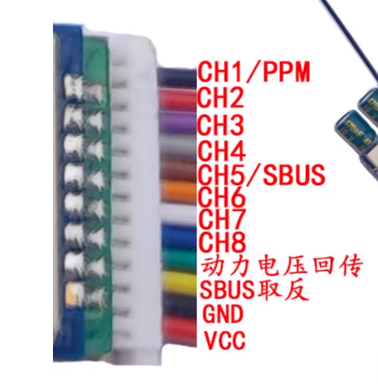
The diagram below shows the output wiring sequence of the receiver; only the following three wires are needed: CH1/PPM, GND, VCC.
The receiver outputs in order: CH1/PPM, GND, VCC
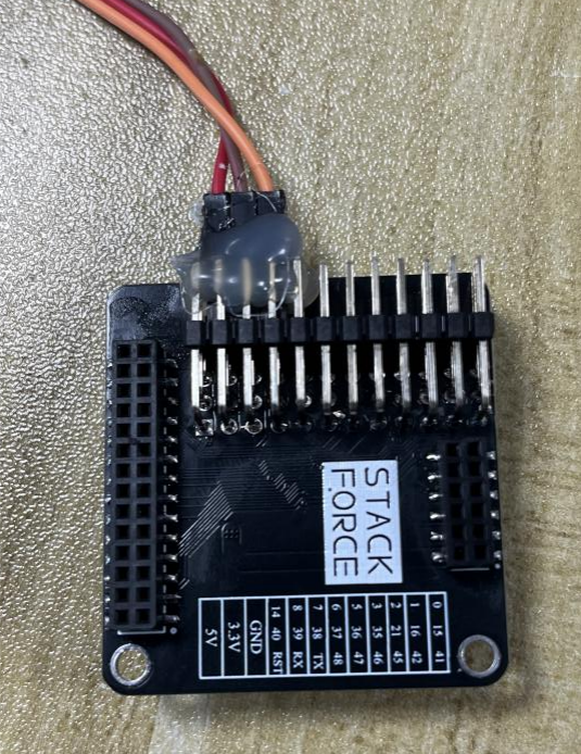
The expansion board has 40 pins, with GND and 3V3 in the middle row, as shown in the diagram below.
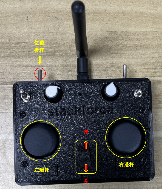
2. Receiver and Remote Control Frequency Pairing
Before pairing frequencies, first turn off the remote control, then power on and off the receiver three times within 10 seconds to enter pairing mode. The receiver indicator light will light up and go out after one second.
Then flip the remote control enable switch down to enable signal transmission, flip the left joystick of the remote control down to the lowest position, and then turn on the remote control. The frequency pairing is successful. After successful frequency pairing, the receiver indicator light will go out.
3. Remote Control Basic Usage Instructions
Joystick and Switch Functions
| Controller | Function | Description |
|---|---|---|
| Enable Joystick | Whether remote control sends signal | Must be flipped before controlling the robot |
| Left Joystick (up/down) | Control robot height | Raise up, lower down |
| Left Joystick (left/right) | Control height of both sides of robot legs | Need to enable shoulder swing function |
| Right Joystick (up/down) | Control robot forward/backward movement | Up to move forward, down to move backward |
| Right Joystick (left/right) | Control robot left/right turning | Turn left, turn right |
Left Joystick with Left Knob Usage
- When the left knob is turned clockwise to the top: Flip the left joystick down to enable shoulder swing function; flip up to disable
- When the left knob is turned counterclockwise to the bottom: Flip down to make the robot jump, flip up to disable jump
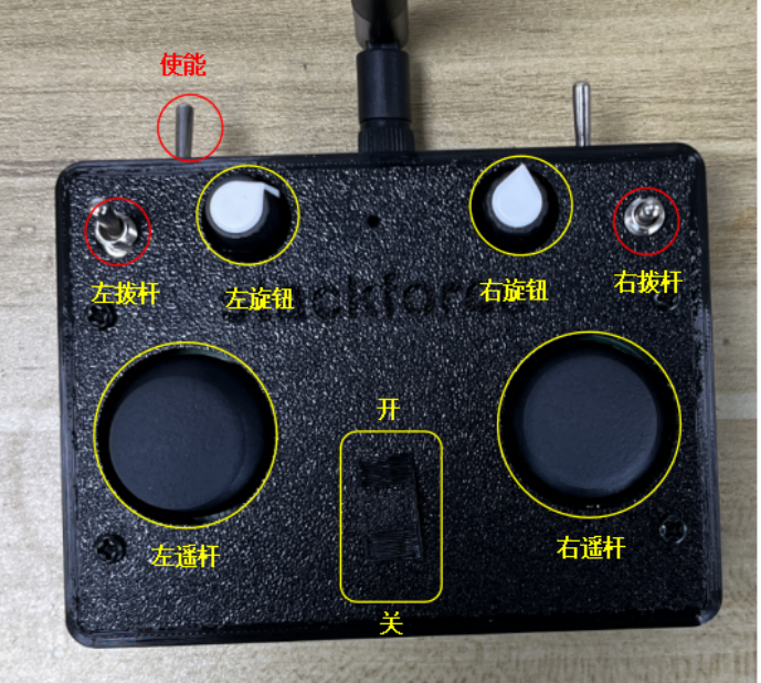
Right Joystick and Right Knob
-
The right joystick has three positions:
- Top position: Disable hub motor
- Middle position: Enable hub motor
- Bottom position: Activate self-stabilizing mechanism
-
Right knob: Adjust balance deviation
4. Robot Power-On Operation Steps
Detailed Operation Process
-
Remote Control Preparation
- Flip the left joystick of the remote control to the lowest position, then turn on the remote control
- Ensure the robot legs are suspended and parallel to the ground
- The robot legs should hang naturally, ensuring smooth wheel rotation for calibration
-
Robot Power-On
- Turn on the robot power switch
- Wait for hub motor calibration to complete
-
Main Control Board Reset
- Flip the left joystick all the way up to reset the S3 chip on the main control board
- Wait for calibration to complete
-
Leg Retraction
- Flip the left joystick all the way down to retract the robot legs
- Place the robot on the ground
-
Hub Motor Activation
- Flip the right joystick to the middle position to start the hub motor
- If the robot cannot maintain balance, fine-tune the right knob on the remote control until the robot maintains balance
Important Reminders:
- Do not over-discharge the remote control battery
- You can use a multimeter to measure battery voltage
- Normal discharge range is generally 25-21V
- If voltage drops below 21V, please charge in time
- If you do not understand the above steps, you can contact technical staff to watch the robot power-on operation video!
System Debugging Guide
This section uses the ID number of the joint motor board as the label for explanation. Please connect strictly according to the wiring diagram.
1. Wiring Guide
Wiring Diagram - Wire strictly according to the diagram to ensure each connection is correct
1. Hub Motor Wiring
Hub motor three-phase line and Hall three-phase line wiring:
- Hub motor three-phase wire welding sequence (left to right): Green, Yellow, Blue
- Encoder wire sequence (left to right): Yellow, Green, Blue, Black, Red
Detailed Wiring Diagram:
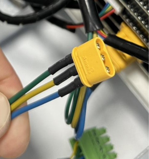 Figure 1: Motor three-phase line wiring | 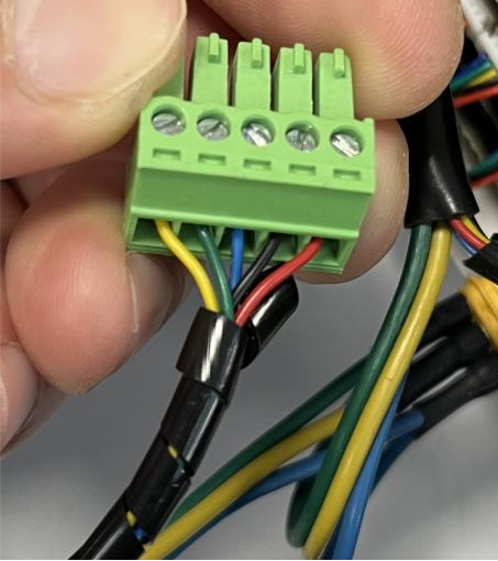 Figure 2: Encoder wiring details |
Left and right hub motor wiring allocation:
- Left hub motor:
- Three-phase line → High current Board B
- Hall encoder line → Hall Board M0 port
Left and right wheel detailed wiring scheme:
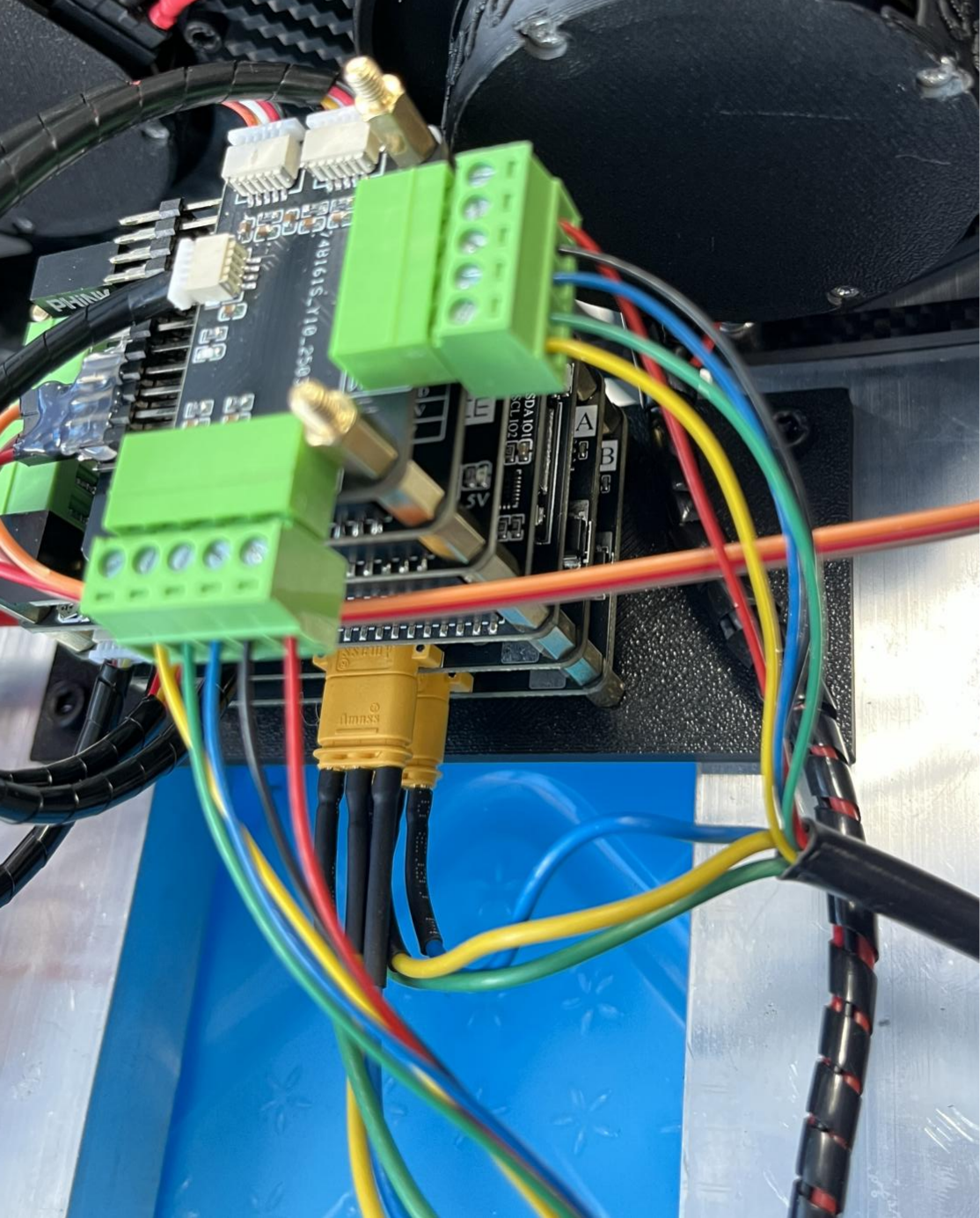 Left hub motor wiring scheme | 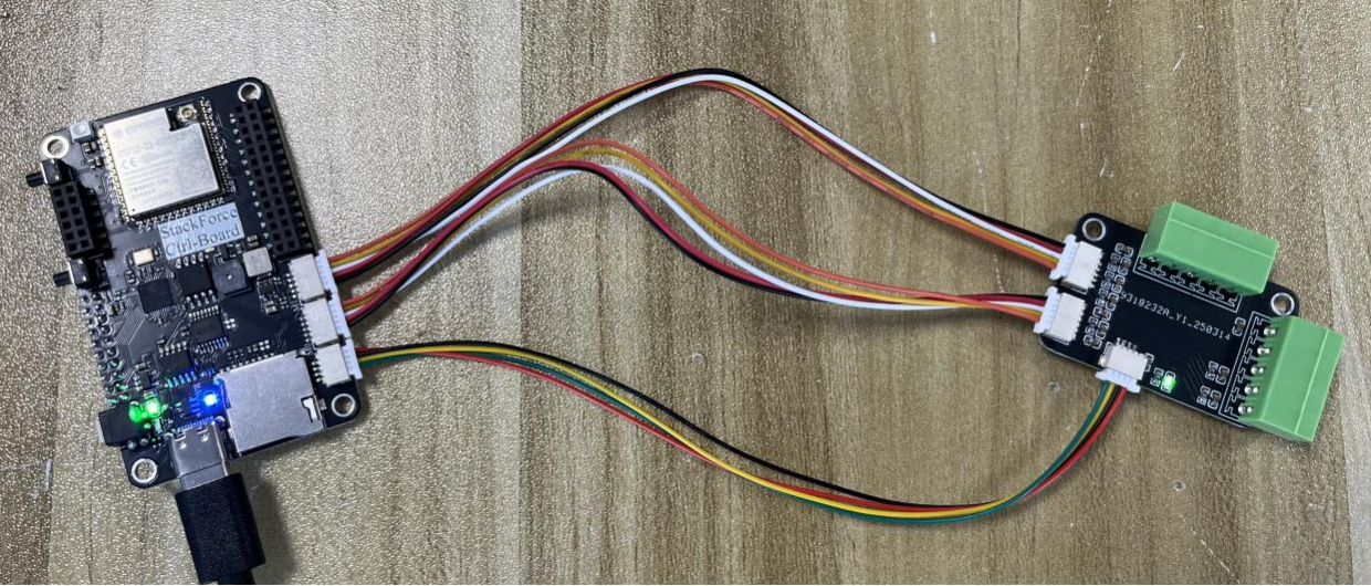 Right hub motor wiring scheme |
2. S1 Firmware Flashing
Pre-flashing Preparation
Important Reminder - USB cable insertion direction is crucial, incorrect insertion may cause device damage
- Insert the USB cable's type-c head with the seam side facing down into the main control board's type-c interface
- Check the main control board indicator light:
- If the main control board lights yellow → Normal, can flash directly
- If the main control board lights green → Press the white self-locking button beside it to switch to yellow light
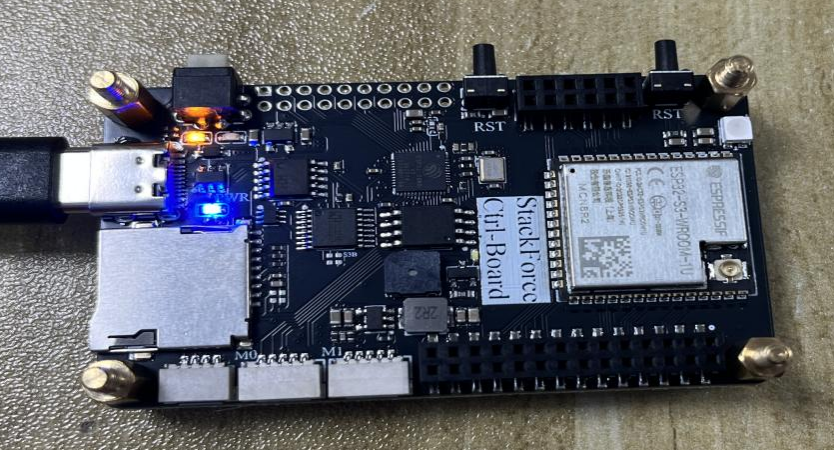
⚠️ Note the USB cable insertion direction
Flashing Steps
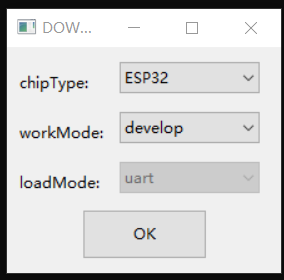
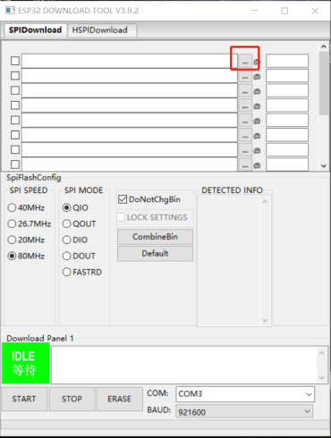
Step 1: Open the flashing tool
- Double-click to open the
flash_download_tool_3.9.2.exetool - After the tool opens, a dialog will pop up, select ESP32
Step 2: Select firmware file
- Click the three dots (📁 icon) in the first row
- In the pop-up folder, select the
target.binfile
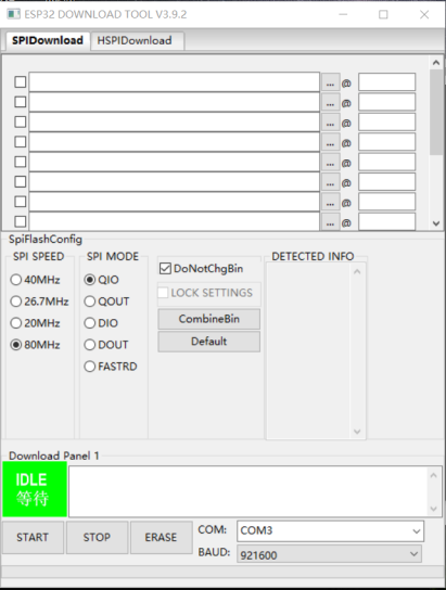
Step 3: Configure flashing parameters
Parameter Configuration Checklist - Please configure according to the following parameters to ensure successful flashing
Configure the following parameters:
- ✅ Select file path (automatically displayed)
- ✅ Check selection
- ✅ Write address:
0x00 - ✅ Clock frequency:
80MHz - ✅ Flash mode:
QIO - ✅ Serial port selection: View CH340 corresponding port through Device Manager
- ✅ Baud rate:
921600
 📋 Parameter configuration step 1 | 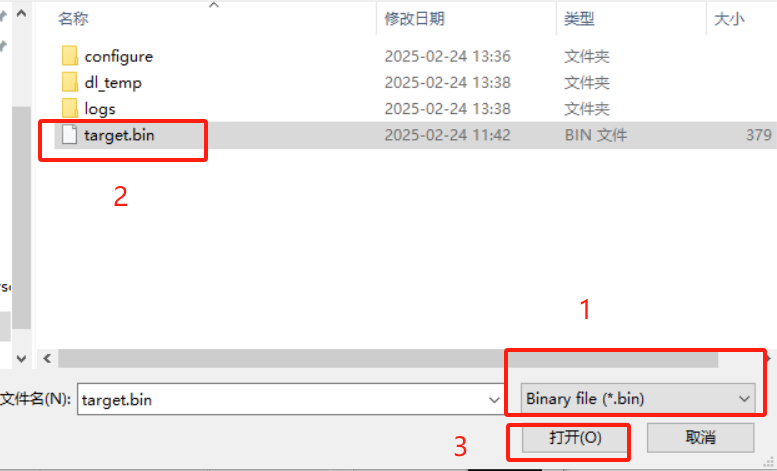 📋 Parameter configuration step 2 | 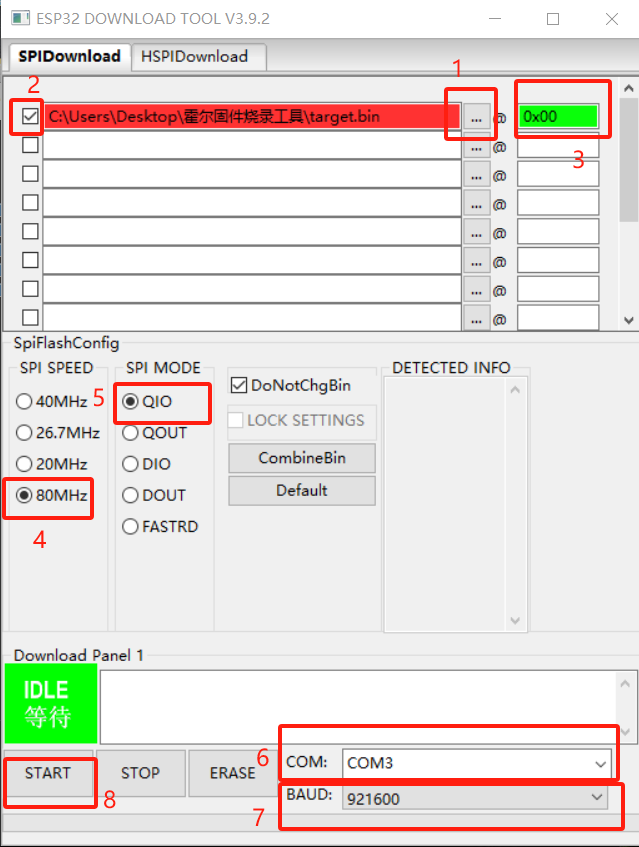 📋 Parameter configuration step 3 |
Step 4: Verify flashing results After successful flashing:
- Assemble the board and connect the wires
- Open the serial assistant (VOFA) and select the corresponding port
- Power on the robot:
- First turn on the remote control
- Flip the left joystick of the remote control to the top
- Flip the top-right lever to the top (L position)
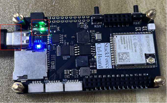
- Press the S1 chip reset button (position marked with red box)
Verification Steps - Please verify according to the following steps after flashing is complete
 ✅ S1 chip reset button position | 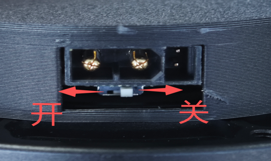 📊 Serial debugging assistant interface |
If the serial print information is as shown in the figure below, it means the hub motor wiring is correct and the S1 firmware was successfully flashed.
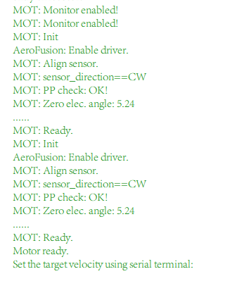
🎉 Flashing successful! Seeing this message indicates everything is normal
3. Checking Terminal Resistance
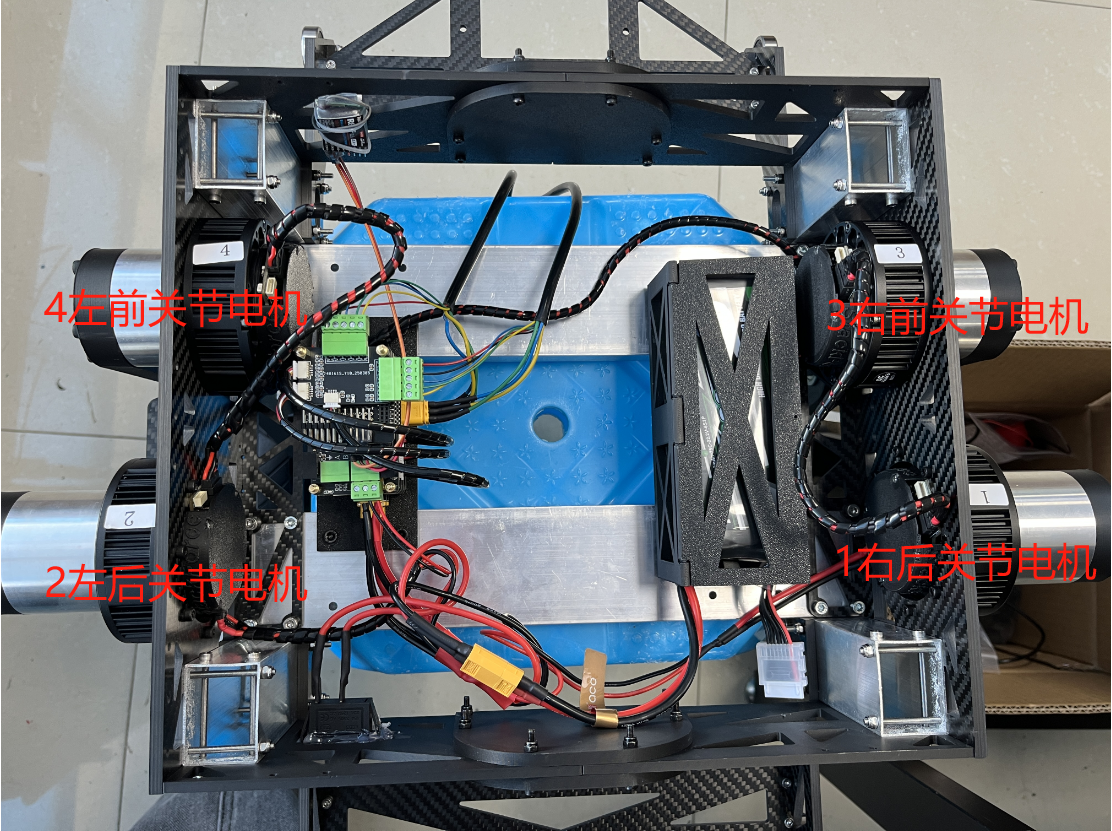
Joint Motor Driver Board ID Numbers
The joint motor driver boards have firmware flashed before shipping and are labeled with labels that are the CAN ID numbers:
| Joint Position | CAN ID Number |
|---|---|
| Left Front Joint Motor Driver Board | 0x04 |
| Right Front Joint Motor Driver Board | 0x03 |
| Left Rear Joint Motor Driver Board | 0x02 |
| Right Rear Joint Motor Driver Board | 0x01 |
Connection and Terminal Resistance Settings
-
Use XT30 (2+2) cable connection:
- Connect the four joint motor driver boards in series
- Only need to open the terminal resistance of one of the motor driver boards in the wiring
- The other three do not need to open terminal resistance
-
CAN Board Terminal Resistance Check:
- Check whether the terminal resistance on the CAN board is open
- Use a multimeter resistance mode to measure the resistance of CAN board H and L terminals
- Normal resistance should be around 60Ω
-
Troubleshooting:
- If the resistance is incorrect, check whether the terminal resistance switches on the back of the other three joint motor driver boards are closed
- Ensure only one terminal resistance is in the open state
4. Calibrating Zero Position
Step 1: Modify Code Settings
In the can.cpp file:
- Scroll down to find the
CAN_control()function
📝 Key code location in can.cpp
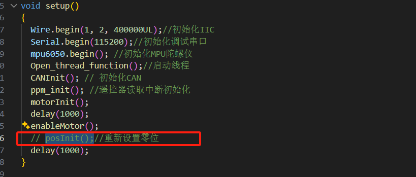
In the main.cpp file:
📝 Key code location in main.cpp
Step 2: Hardware Preparation and Flashing
-
Robot Preparation:
- First let the joint motor legs hang naturally vertically downward
- Insert the USB cable into the main control board (note that the side of the type-c interface with the seam is down, the side without the seam is up)
- After insertion, the main control board S3 serial port should light green light
- If it lights yellow, press the white button on the main control board to switch to S3 chip
-
Program Flashing:
- Flash the modified program
🔧 Hardware preparation completed state
-
Power-on Test:
- Open the serial assistant after flashing the program
- Power on the robot (flip the top-right lever of the remote control to the top (L))
- Reset the S3 chip
- Observe that the initial angles of the joint motors printed by the serial port are all near 0
-
Verify Angle Data:
- Shake one of the robot's big arms
- Which data changes corresponds to the angle data of that big arm position
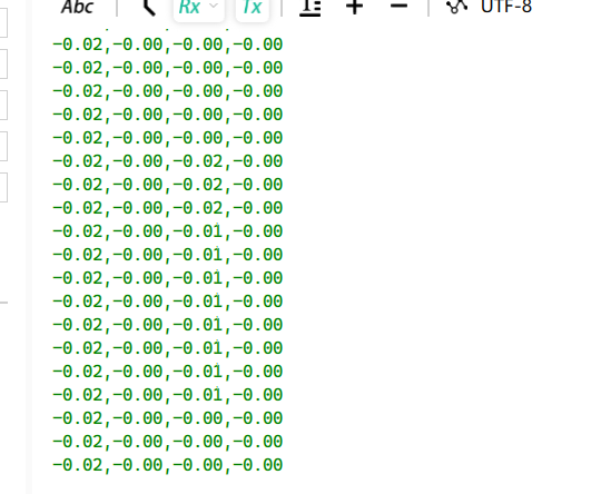
📊 Serial output - angle data verification
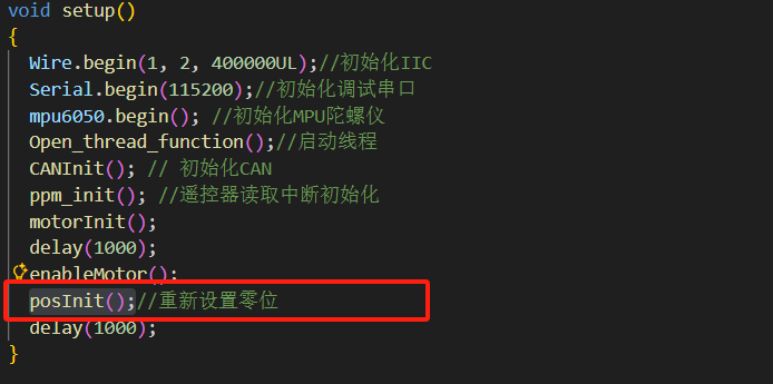
Step 3: Complete Zero Position Settings
In the main.cpp file:
✅ main.cpp zero position setting completed
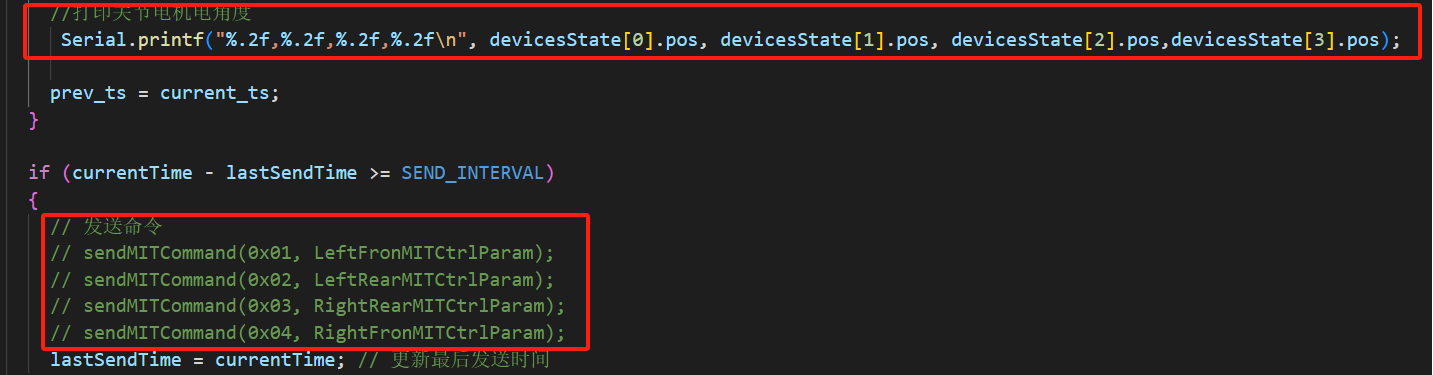
In the can.cpp file:
- After commenting
posInit(), you need to uncomment the CAN command sending in theCAN_Control()function in the can.cpp file - Comment out printing the joint motor electrical angle
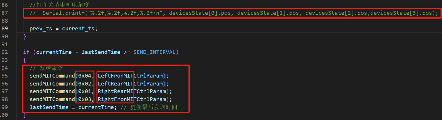
✅ can.cpp final configuration completed
Step 4: Final Adjustment
- Re-flash the program to the S3 chip
- Control Test:
- Power on the robot
- Control the leg height joystick
- Observe whether the leg height changes follow the left joystick control
- Height Balance Adjustment:
- Place the robot on the ground
- Retract the robot legs to the minimum
- Observe whether the heights on both sides of the robot plane are consistent
- If not consistent, adjust the
leftYandrightYvalues in the robot.cpp file
Height Balance Adjustment Diagram:
 ⚖️ Height adjustment diagram - before adjustment | 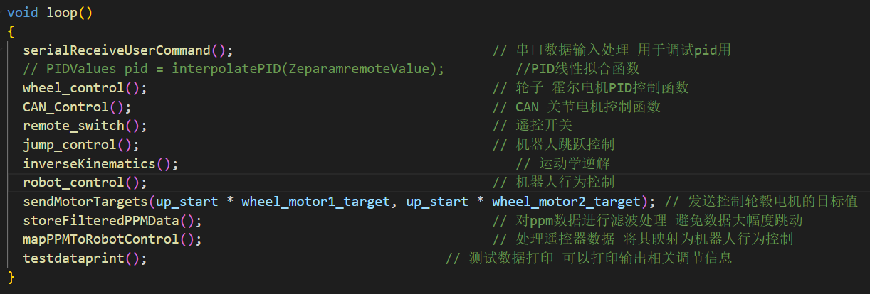 ⚖️ Height adjustment diagram - after adjustment |
5. Debugging PID Parameter Values
Debugging Preparation
PID Parameter Debugging Interface:
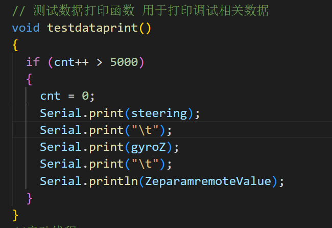 🔧 PID debugging steps - function comments | 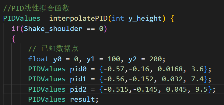 🔧 PID debugging steps - parameter printing |
Debugging Steps
Debug PID parameters at three height values:
| Height Value | Corresponding Position | Fill Parameters |
|---|---|---|
| 0 | Lowest point | pid0 |
| 100 | Midpoint | pid1 |
| 200 | Highest point | pid2 |
Each pid parameter includes:
- Speed loop Kp
- Upright loop Kp
- Upright loop Kd
- Robot X-axis Kp
Debugging Process
-
Debug each height individually:
- Debug the PID parameter values for three different height values separately
- Ensure the robot can maintain balance at each height
-
Fill parameters:
- Fill the debugged PID parameters of the three height values into the PID linear fitting function in order
- Fill the PID parameter values of the lowest point into pid0
- Fill the PID parameter values of the midpoint into pid1
- Fill the PID parameter values of the highest point into pid2
-
Final verification:
- After debugging is complete, uncomment the PID linear fitting function
- Flash the program into the S3 program
- Power on the robot according to the robot power-on steps
- Ground verify that the PID parameters meet the robot's motion balance and operational requirements
If you need to refer to operation videos, you can contact the technical staff in the group to obtain the robot power-on operation video!
Hardware Assembly
Detailed Assembly Guide
Assembly Documents and Videos
📄 Assembly Documents
- 📗 Detailed Assembly Manual (English Version)
- 📘 Detailed Assembly Manual (Chinese Version)
- 📋 Bill of Materials BOM (Chinese Version)
- 📋 Bill of Materials BOM (English Version)
🔧 Development Tools
- ⚙️ VSCode + PIO Environment Configuration Tutorial
- 📦 MingW64 Toolkit
- 🔌 CH340 Driver Installation Guide
- 💾 CH340 Driver Package
💻 Firmware and Programs
- ⚡ S1 Firmware Flashing Tool
- 🔧 Latest Controller Program
- 🔧 Joint Debugging Program
- 🖼️ Program Debugging Screenshots
📚 Technical Documentation
🗂️ 3D Models and Schematics
- 📐 Robot 3D Model (STP Format)
- 🔌 Main Control Board Schematic
- 🔌 CAN/485 Expansion Board Schematic
- 🔌 Servo IMU Module Schematic
🎥 Video Tutorials
Detailed Assembly Steps
Phase 1: Mechanical Framework Construction
- Assemble base structure
- Install wheel-leg components
- Connect main body framework
Phase 2: Electronic System Integration
- Install main control system (S1/S3 boards)
- Configure sensor modules
- Set up communication interfaces
Phase 3: System Debugging
- Execute hardware self-check
- Verify system functionality
Conclusion
The StackForce Giant Bipedal Wheeled Robot represents the latest development level of wheel-legged robot technology. We are committed to providing developers with the most powerful tools and most comprehensive support to jointly advance the development of robot technology.
Whether you are a student, researcher, or engineer, StackForce can provide you with an innovative platform with unlimited possibilities. We look forward to seeing you create amazing applications!
Tech Support & Product Discussion
Thank you for choosing our products! We are here to provide you with different support to ensure that your experience with our products is as smooth as possible. We offer several communication channels to cater to different preferences and needs.