Getting started with the Two-Wheeled Biped Robot Based on the StackForce Development Platform
This tutorial only provides assembly and debugging instructions to help developers build a complete wheeled-leg robot as quickly as possible. If you need to learn the underlying principles of wheeled-leg robots, you may refer to the Bilibili tutorial video by DengGe. For secondary development, you can search for tutorials on other websites or forums.
Introduction
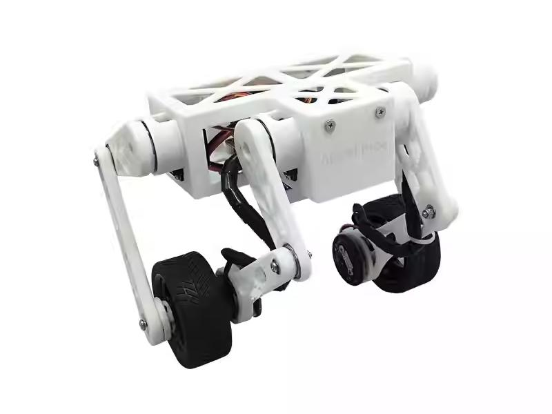
The StackForce two-wheeled biped robot is developed based on the StackForce lightweight robotics development platform. Its core hardware is composed of the StackForce series main control board, motor driver board, and servo driver board.
The robot includes a full-body kinematic model and a state-adaptive self-stabilization algorithm. With the StackForce platform’s real-time computing power, it supports multi-posture control, self-stabilization on complex terrain, stair descent, and stable movement on various slopes. The platform supports RC transmitters, Bluetooth, serial communication, and wireless control. Users can program and adjust the system as needed. The product provides complete installation tutorials and video courses, making it a cost-effective desktop two-wheeled biped robot.
Technical links
-
DengGe’s open-source tutorial video on Bilibili: https://www.bilibili.com/video/BV1kz421B73V/?share_source=copy_web&vd_source=dd1f489993457f044ad480eab0e73bdc
-
Open-source code for the wheeled-leg robot course: https://gitee.com/StackForce/bipedal_wheeled_robot
-
Documentation for the StackForce lightweight robotics development platform: http://stackforce.cc/#/
-
Open-source robot projects for the StackForce lightweight robotics development platform: https://gitee.com/StackForce
-
StackForce_Mini_Wheeled_Legged_Robot theory and code learning https://github.com/Seeed-Projects/AI_Robotics_Academy/blob/main/Seeed_Mini_Wheeled_Legged_Robot/English/README.md
Main Features
- Open-source and low cost: Follows an open-source license; all source code and design files are fully available, allowing developers to freely study, modify, and perform secondary development.
- High-performance motor control: Equipped with FOC (Field-Oriented Control) technology, supporting open-loop/closed-loop speed, position, and torque control for precise motion control.
- Powerful hardware support: Uses an ESP32 main controller with rich interfaces such as I2C, SPI, and PWM, enabling flexible feature expansion.
- Comprehensive capabilities: Supports self-balancing, high-speed movement, posture stabilization, and wireless control, adapting to various complex terrains.
- Easy to learn and use: Comes with complete example code and video tutorials, significantly lowering the learning barrier for beginners.
Specification
| Specification | Details |
|---|---|
| Main Control Board | StackForce main control board |
| Motor Driver Board | 5A dual-channel brushless motor driver (low-power) |
| Motors | 2208 gimbal brushless motors |
| Servo Driver Board | Multi-channel servo driver with integrated IMU |
| Power Supply | 12.6V lithium polymer battery |
| Encoder | MT6701 14-bit high-precision magnetic encoder |
| Wireless Control | WiFi remote control + PS4 Bluetooth wireless controller |
| Total Weight | 540 g |
| Dimensions | 10.5 × 21.0 cm (L × W), Height 12.0–21.0 cm |
BOM
| Item Name | Quantity | Unit | Specifications | Notes/Standards |
|---|---|---|---|---|
| Electronic Components | ||||
| StackForce Main Control Board | 1 | pc | StackForce | |
| StackForce 5A Low-Power Driver Board | 1 | pc | StackForce | |
| StackForce Servo Board | 1 | pc | StackForce | |
| MT6701 Encoder | 2 | pc | StackForce | |
| 2208 Gimbal Motor | 2 | pc | ||
| DS041MG 500–2500 Servo | 4 | pc | ||
| MC6C-MINI Remote Controller | 1 | pc | ||
| MC7RBv2 Receiver | 1 | pc | ||
| 12V Li-Polymer Battery | 1 | pc | 19×34×42mm | |
| MR30-U Motor Connector | 2 | pc | For motor | |
| SH1.0-5P Encoder Cable | 2 | set | For encoder | |
| 3P Dupont Wire (Female-Female) | 1 | set | For receiver | |
| Mechanical Hardware | ||||
| M3 Lock Nut | 4 | pc | M3 | GB889.1-86 |
| M3 Nut | 4 | pc | M3 | DIN934 |
| Nylon Standoff | 4 | pc | 5×3.2×9mm | ABS |
| M3 Washer | 4 | pc | M3 | 304 Stainless |
| Radial Magnet | 2 | pc | 6×2.5mm | |
| Round Head Screw M2×4 | 24 | pc | M2×4 | GB/T845 |
| Round Head Screw M2×10 | 12 | pc | M2×10 | GB/T845 |
| Round Head Screw M3×6 | 4 | pc | M3×6 | GB/T845 |
| Round Head Screw M3×8 | 4 | pc | M3×8 | GB/T845 |
| Round Head Screw M3×16 | 4 | pc | M3×16 | GB/T845 |
| Round Head Screw M4×18 | 2 | pc | M4×18 | GB/T845 |
| M2×6 Self-tapping Screw | 16 | pc | M2×6 | GB/T845 |
| Flat Head Screw M2×6 | 46 | pc | M2×6 | 304 Stainless |
| Flat Head Screw M3×6 | 16 | pc | M3×6 | 304 Stainless |
| M3×7+4 Copper Standoff | 4 | pc | M3×7+4 | Copper / GB |
| 6704ZZ Bearing | 4 | pc | Ø27×Ø20×4mm | |
| 6701ZZ Bearing | 6 | pc | Ø18×Ø12×4mm | |
| Structural Components | ||||
| 3D Printed Parts | 29 | pc | ||
| 1:10 Wear-Resistant 6030-6085 Tires | 2 | pc |
Table of Contents
Assembled Version Tutorial
StackForce Wheeled_Legged_Robot Basic Operation Manual (PDF)
You can remotely control the robot by simply starting it in the order specified in the PDF document.
Kit Version Tutorial 1 - Assembly
Mini-Wheeled-legged robot installation document.pdf
The assembly has many steps, so please follow the guide carefully. Some holes are made for self-tapping screws, and it is normal if the screws in the package differ from those in the tutorial. This will not affect assembly, and you may use suitable replacement screws if needed.
During assembly, pay attention to the tightness of the screws. Do not overtighten them to avoid stripping or damaging the threads.
Kit Version Tutorial 2 - Calibration
Please first download the code files required for calibration.
Environment Setup
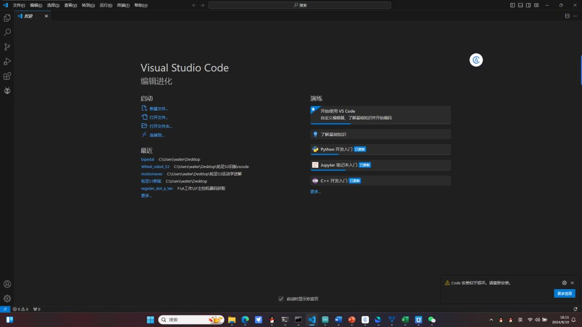
Step 1: Download Visual Studio Code.

Step 2: Open Visual Studio Code, then search for and install the PlatformIO IDE extension from the Extensions Marketplace.
After clicking install, PlatformIO will automatically download additional required components. In some cases, MinGW may be missing, which will prevent you from creating new folders. If this happens, you will need to install MinGW-w64 manually.
Step 3:Download MinGW-w64
Wheeled-Legged Robot Tool Pack Download Link(Including MinGW-w64)
After downloading the file, extract it and find the mingw64 folder inside the tool pack.
Extract it, then install it in a directory that uses only English characters.
Open the extracted folder → open the bin folder → copy the path of the bin directory
(for example: D:\ming\mingw64\bin).
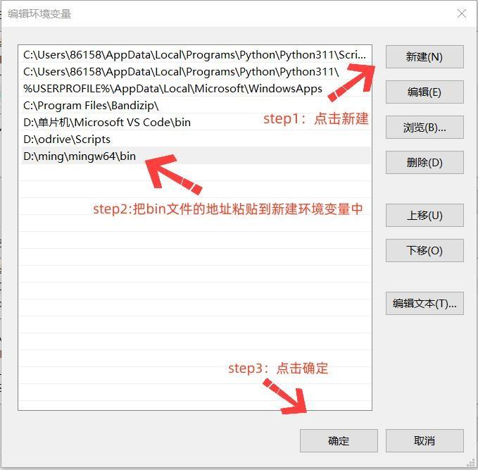
Environment configuration:
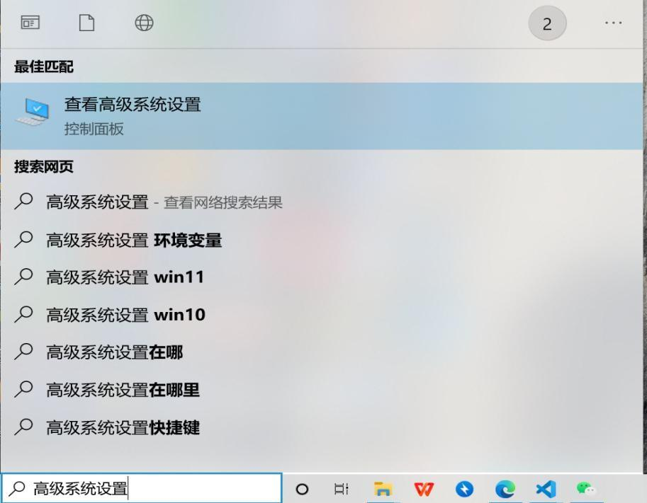
Search for and open Advanced System Settings on your computer → Environment Variables → System variables → Path → New → paste the bin path copied earlier → click OK.
- 1: Search for and open
Advanced System Settings.
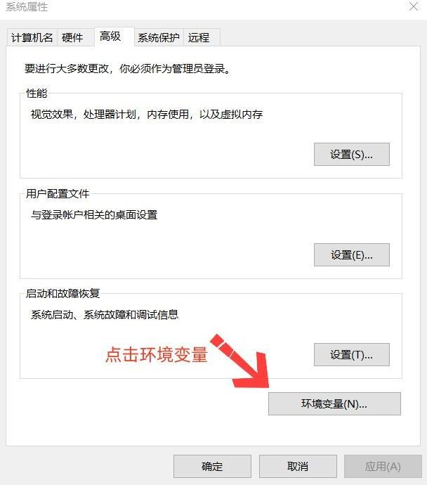
- 2: Click
Environment Variables.
- 3: Double-click
Pathunder System variables.
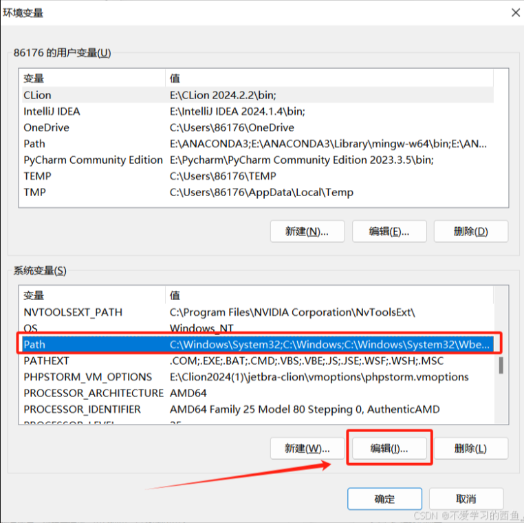
- 4: Create a new environment variable entry.
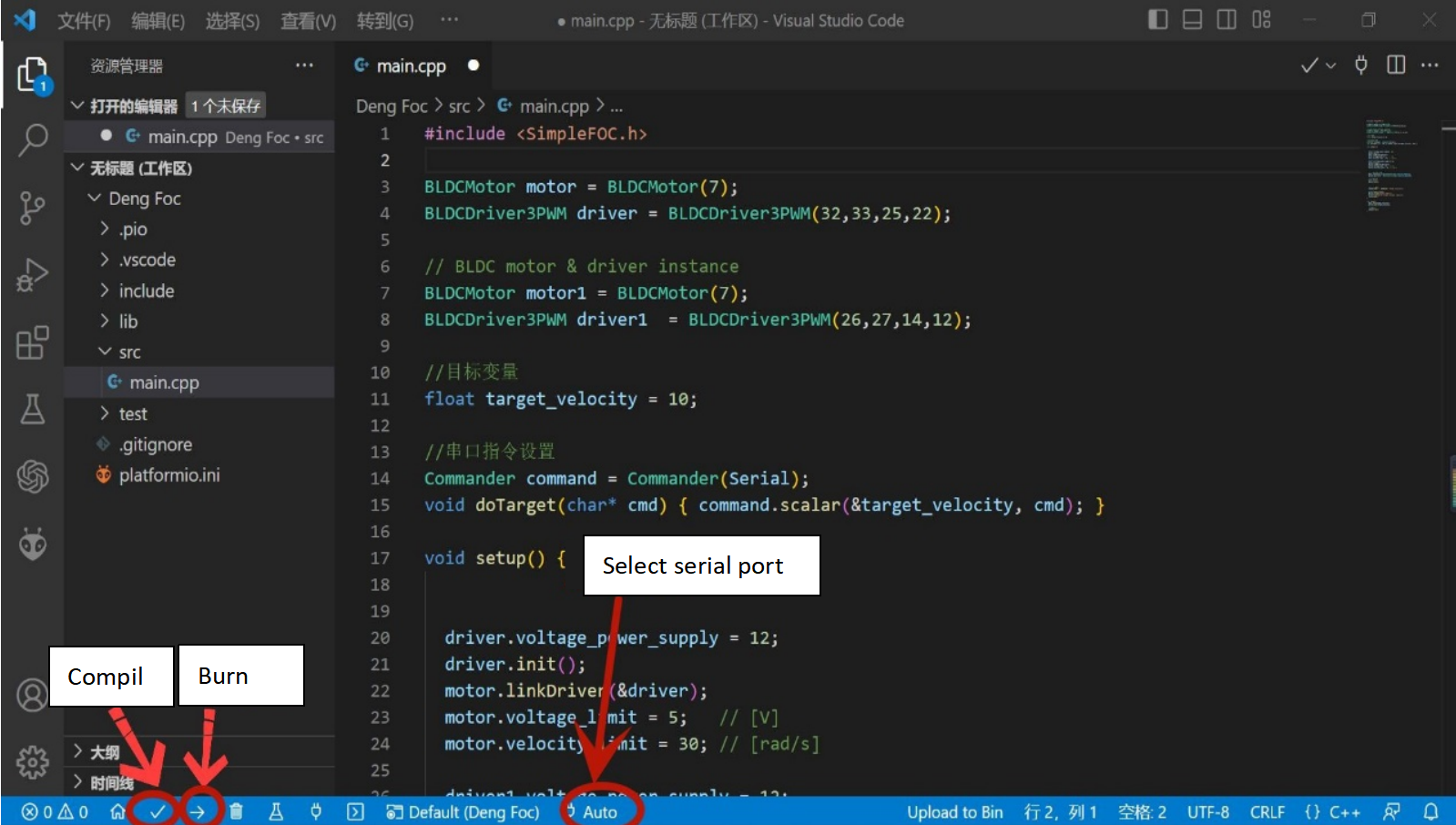
Step 4: Compile and Upload Button Instructions
(√: Compile the program →: Upload the program to the hardware Auto: Select the serial port)
The following explains the upload buttons. Do not upload the program yet. Developers can review the upload process here first.
After connecting the computer to the hardware, click Auto (optional).
The system will automatically detect and recommend a serial port.
After selecting the serial port, click Compile (optional) and Upload to flash the program to the hardware.
S1 Flashing and Debugging
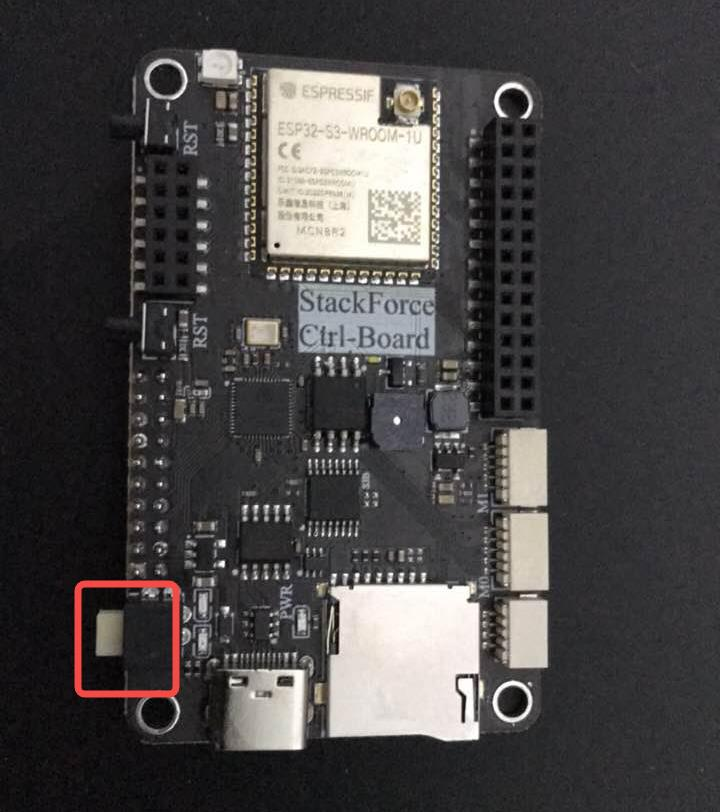
Connecting the S1 Chip
Connect the USB cable. The side with the gap on the USB connector should face up, and the side without the gap should face down. Release the white button to switch to the S1 chip (the yellow light will turn on).
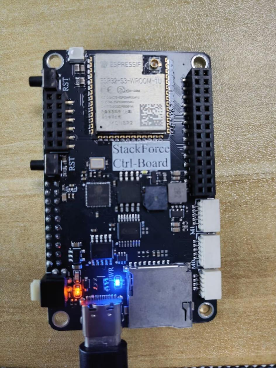
Note: Why is there an upper and lower side?
Because the board has two chips—S1 for the motor program and S3 for the servo control program—the Type-C connector uses two separate pin rows for communication. Each chip uses a different row for flashing. The white button switches which chip the computer will flash.
Flashing the S1 Program
Method 1: According to the pre-burned S1 motor control program, you can skip ahead to Vofa Serial Assistant Download and Usage Guide.
Method 2: Reflash the S1 motor control program (not recommended)
Open the project BLDC_Control in VS Code.
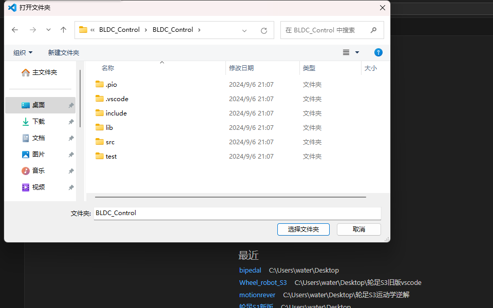
This allows PlatformIO to automatically install the required libraries, so do not drag the project folder directly into VS Code. Instead, open a new VS Code window and use File → Open Folder.
Locate the folder where the S1 program is stored, then click Select Folder.
Before flashing, you need to modify the registration code and the communication mode:
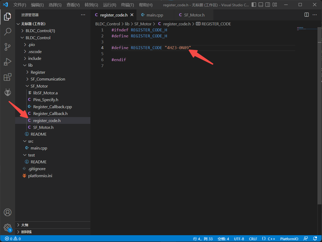
Modify the registration code:
Each board has a unique registration code.
Your registration code is printed on the label attached to the main control board package.
Enter that code into the corresponding field.
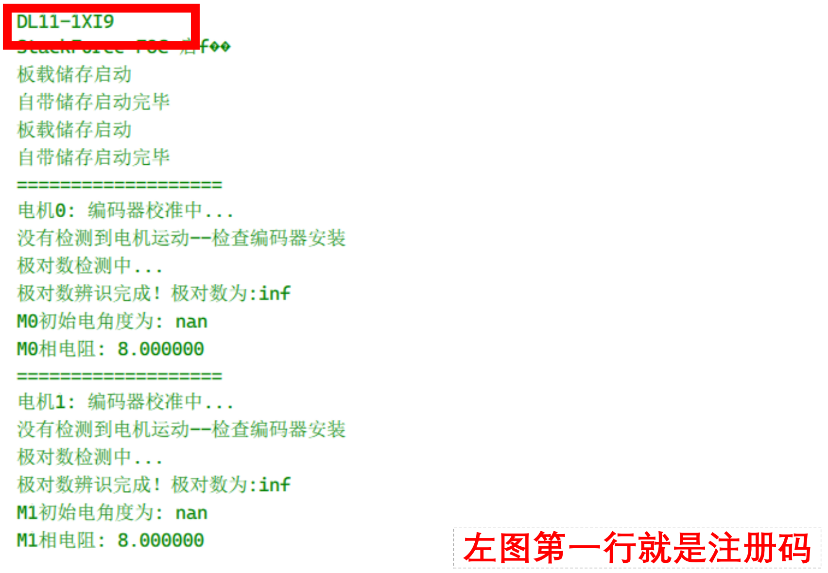
You can also read the registration code from the S1 serial output (explained earlier in the installation guide).
Modify the communication mode:
Change the value at the location shown in the image to ONBOARD. (USB = serial communication between the S1 chip and the computer, ONBOARD = communication between the S1 and S3 chips.)
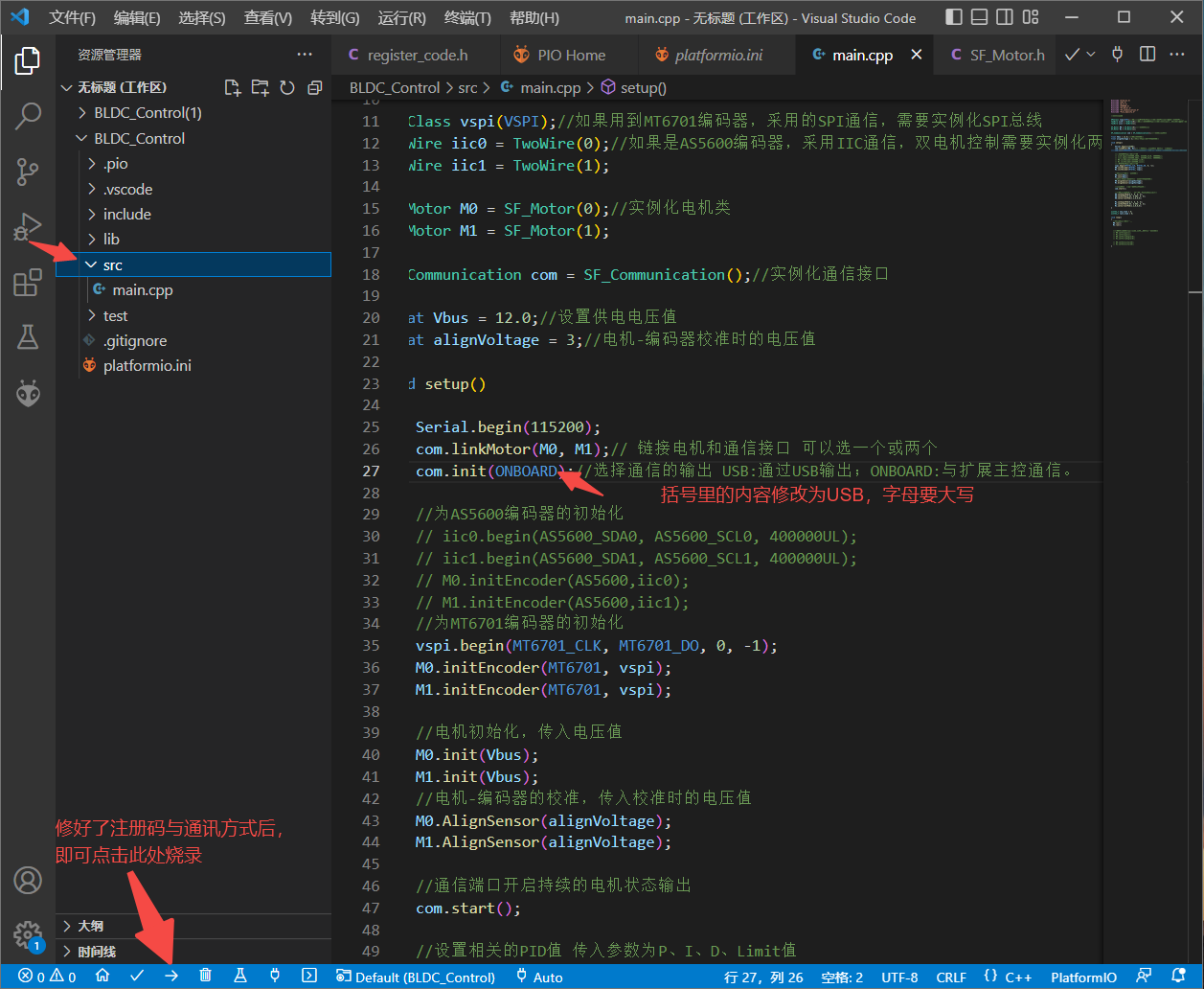
After making the changes, click the → icon in the lower-left corner to flash the program.
Common issues during flashing and how to resolve them:
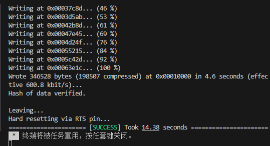
- Successful flashing result
- This is the S3 chip, which does not match the S1 program
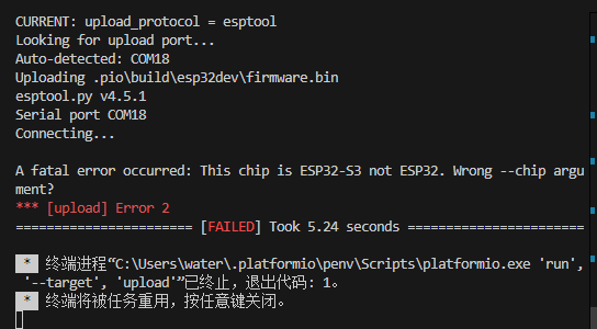
Solution:
Check whether the USB cable is plugged in upside down — the side without the gap must face up.
Check whether the white button is released. When released, the yellow LED lights up, indicating the board is in S1 flashing mode.
- Serial port is occupied
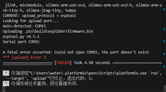
Solution:
Check whether another program is using the serial port.
Make sure the Vofa serial monitor is closed.
Check that all other serial assistants have released the port.
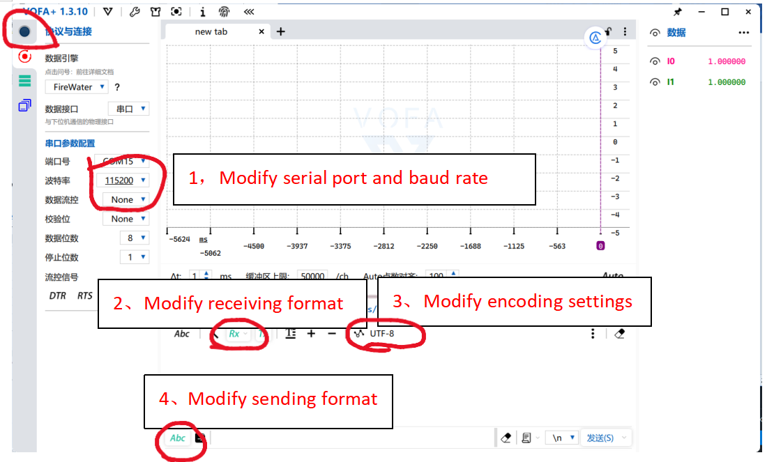
Vofa Serial Assistant Download and Usage Guide
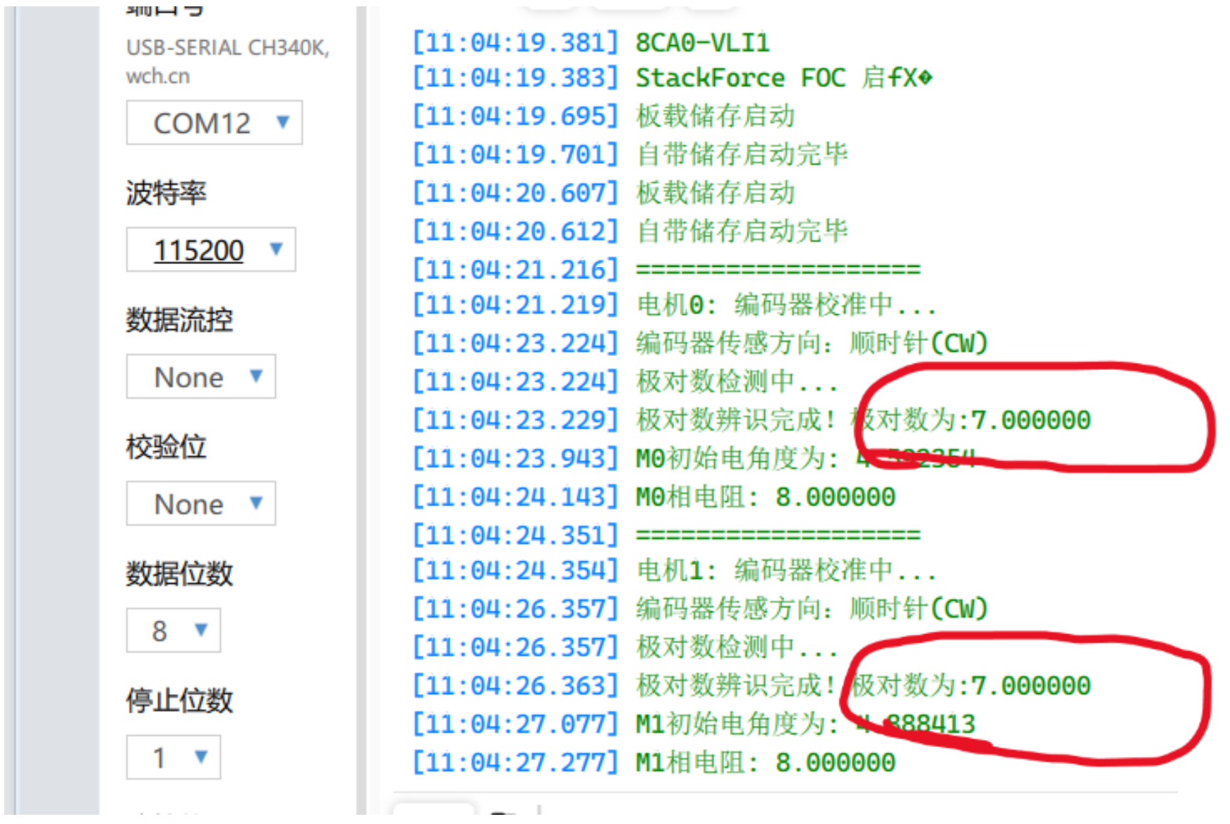
Next, open the serial assistant and set the baud rate to 115200 to check the serial output. Vofa Serial Assistant download link: Download Center | VOFA-Plus
S1 Motor Control Program Debugging – Pole Pair Calibration
Hold the robot so the wheels are off the ground, then press the S1 reset button.
The pole pair information will appear in Vofa. Wait for the wheels to finish the self-test rotation.
If the detected pole pair value is 7, calibration is successful, as shown below:
If the pole pair value shows inf or other text, check whether the power is on, verify the wiring, and ensure the magnet is installed correctly.
If the detected value is 6, 8, or anything other than 7, the wheel may be mounted too tightly
(refer to the wheel-leg installation guide and search for motor bearing installation to reinstall).
The wheel may also be touching the ground or another object.
Each time the robot powers on or S1 resets, the wheels must be off the ground for self-test to run properly.
Repeat the process and press the S1 reset button until the pole pair shows 7.
S3 Offset Value Acquisition
After finishing the S1 flashing, switch to the S3 chip and flash the S3 program. (Ensure the USB port’s gap faces downward. Press the button shown in the image—when the light turns green, it indicates the system has switched to S3.)
Be sure to remove the thigh assembly before flashing the program.
-
- In VSCode, open the bipedal_calibrate folder (offset-value calibration program), flash the program directly, then open Vofa and set the baud rate to
115200.
You will see serial output like0,0,0,0, which represents the offset values ofservos 1, 2, 3, and 4.
- In VSCode, open the bipedal_calibrate folder (offset-value calibration program), flash the program directly, then open Vofa and set the baud rate to

-
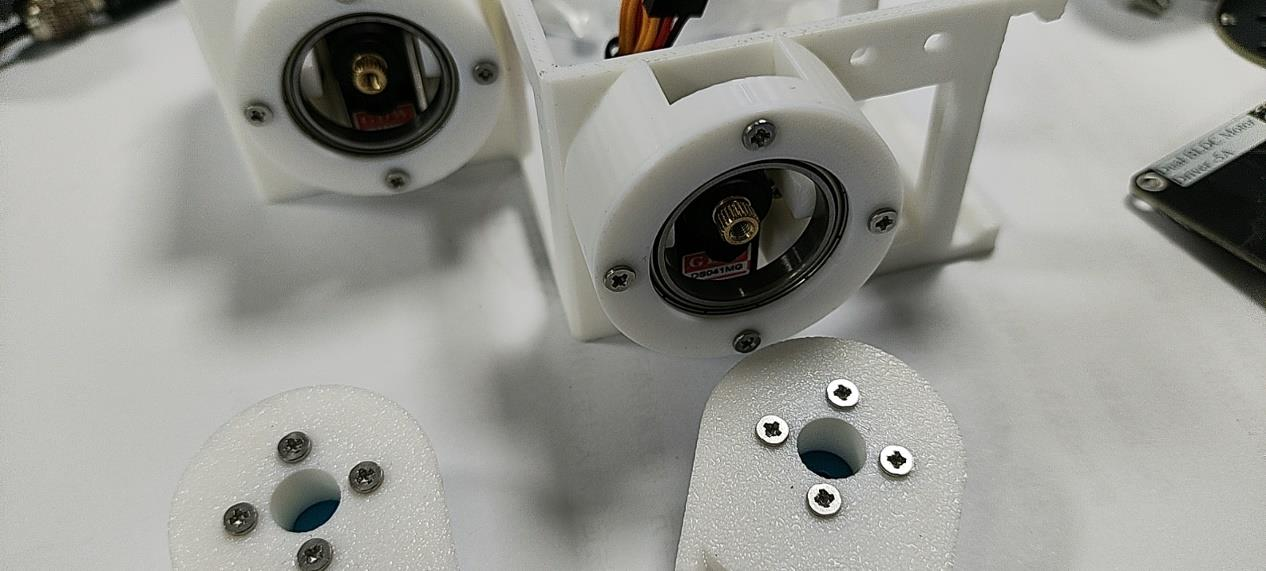
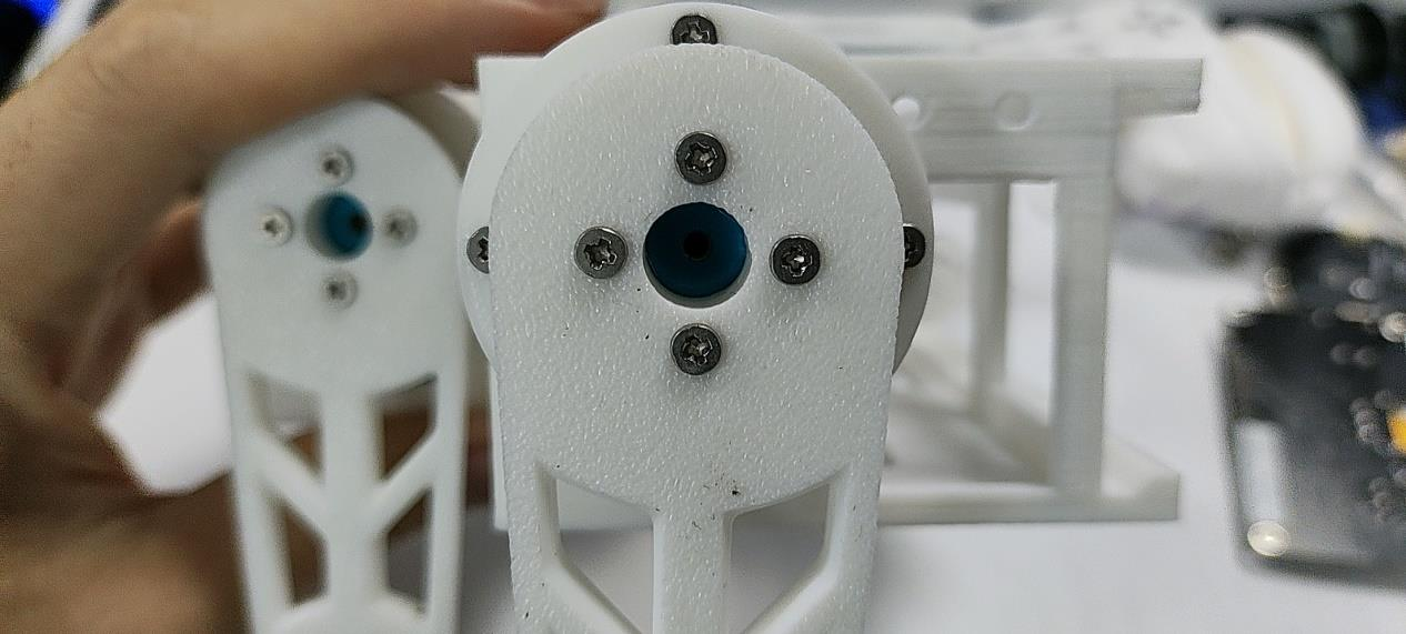
- Power on the battery. After the servos finish rotating, install the legs so they are as vertical to the ground as possible.
-
- In the serial terminal, enter commands like
1,2,3,4to control the servos until the legs are perfectly vertical.
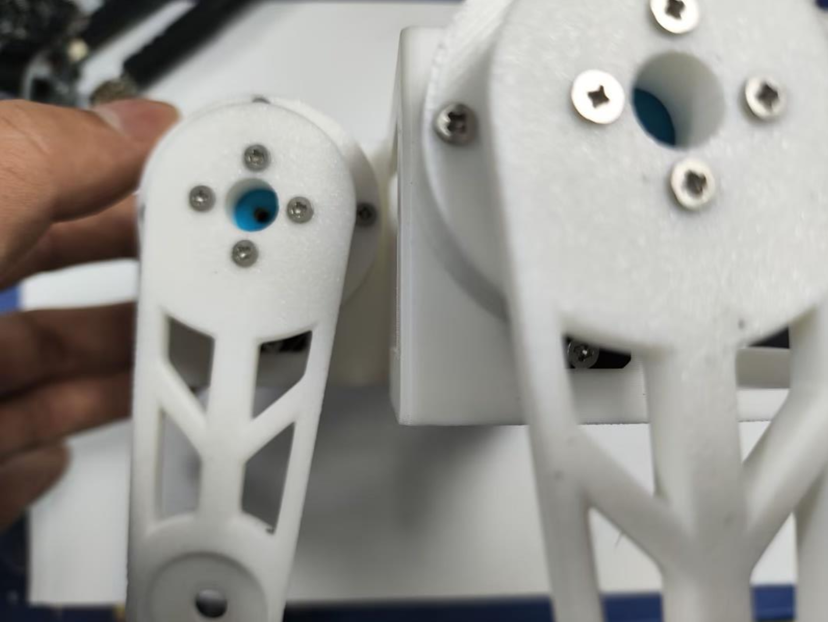
Direction guide: When the leg is facing you, clockwise is negative, counterclockwise is positive.
- In the serial terminal, enter commands like
For example: In the image above, servo 1 is tilted slightly left, and servo 2 is tilted slightly right.
Enter 5,-6,0,0 to correct servos 1 and 2 back to vertical. (5 means rotating servo 1 counterclockwise by 5 units; -6 means rotating servo 2 clockwise by 6 units.)
Adjust servos 3 and 4 using the same method:
Use 0,0,x,0 to control servo 3, and 0,0,0,x to control servo 4.
After finishing all offset adjustments, tighten the black screws inside the servo housing to secure the legs.
Record the current offset values — they need to be written into the S3 servo control program below.
S3 Calibration and Debugging
StackForce Wheeled_Legged_Robot Basic Operation Manual (PDF)
1. Modify Offset Values
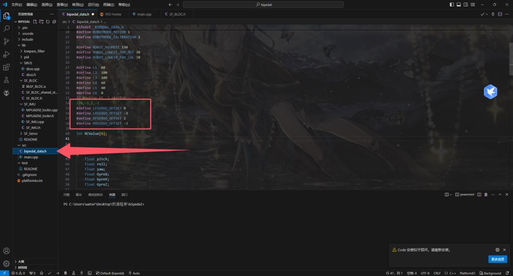
Open the bipedal folder (servo control program) in VS Code.
In the bipedal_data.h file, update the offset values under OFFSET.
Enter the offset values obtained from the previous program into the corresponding positions shown below.
2. Servo Debugging
- After flashing the program, unplug the USB.
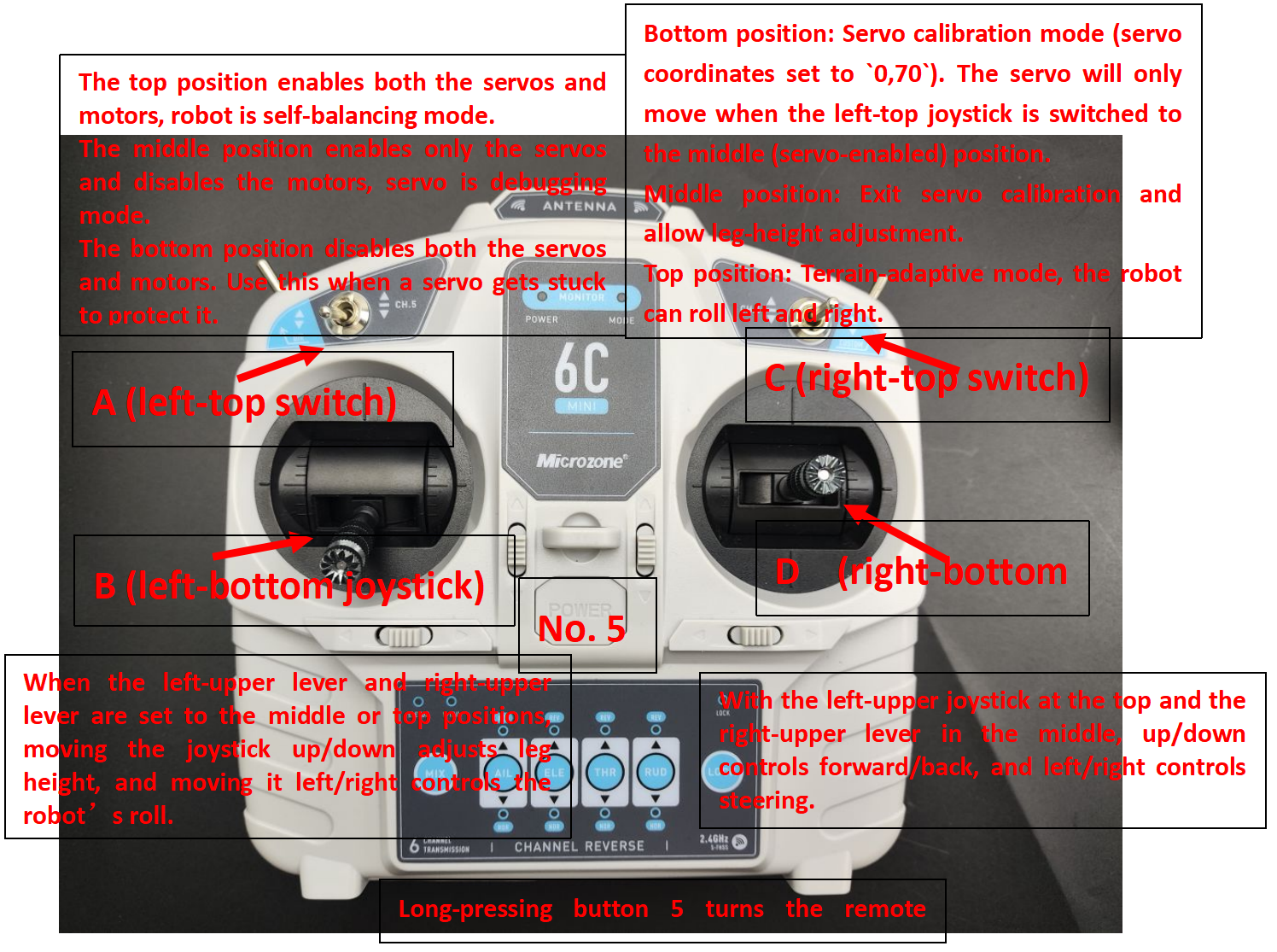
Long-press 5to turn on the remote controller.
Set switches:A (top-left) to middle,B (bottom-left) to down,C (top-right) to down. - Hold the robot and keep it level so gyro calibration and motor calibration can proceed.
Press the power button to turn on the robot. - Wait about 10 seconds for self-check to complete.
SetA to the middleto enable the servos. They will return to the initial position.
SetC to the middleto exit servo calibration.
Slide B to adjust leg height (wheel Y coordinate).
Slide D to move the wheels forward/backward (wheel X coordinate). - Wheel-leg robot movement note:
When D is pushed forward, the servos rotate to move the wheel’s X coordinate backward. The wheel-leg robot tilts forward, causing the robot to move forward.
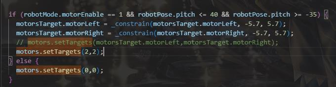
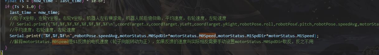
3. Set SpdDir
Set a fixed rotation direction for the motors. In the main file, search for motors.setTargets and set the torque of motor 0 and motor 1 to 2.
Use Vofa to view the motor speeds. Set Vofa’s baud rate to 921600 and connect to S3.
Flash the program to S3, open Vofa (baud rate 921600), set the remote controller’s A switch up to enable the motors, power on, and hold the robot while it completes self-check. (You may first check with Vofa–S1 to confirm whether self-check passed.)
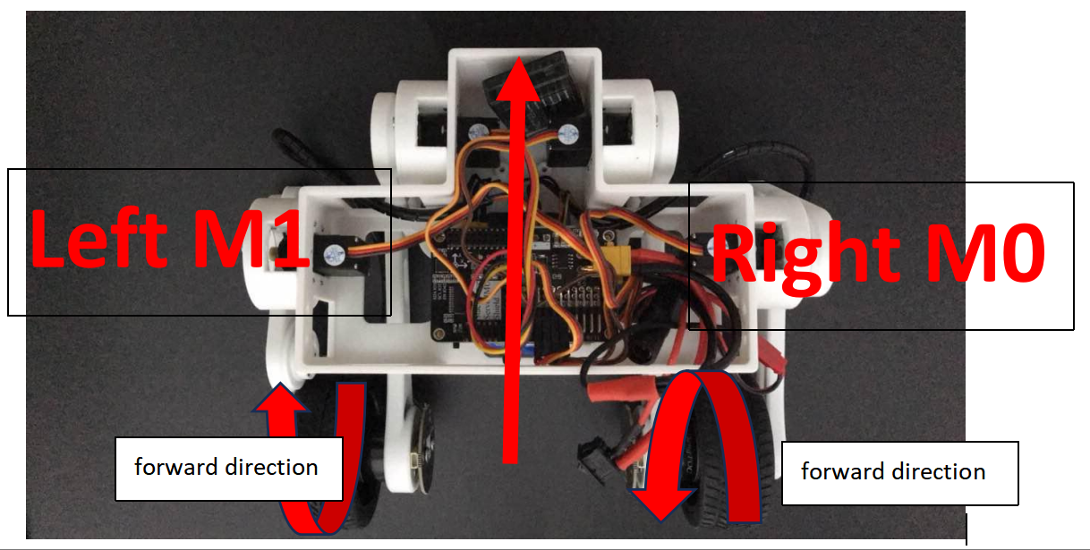
Check motor rotation:
-
Left motor: forward rotation should show positive speed.
If the third value (M1 speed) is negative, invertmotorStatus.M1SpdDir. If it is positive, no change is needed. -
Right motor: backward rotation should show negative speed.
If the second value (M0 speed) is negative, no change is needed. If it is positive, invertmotorStatus.M0SpdDir.
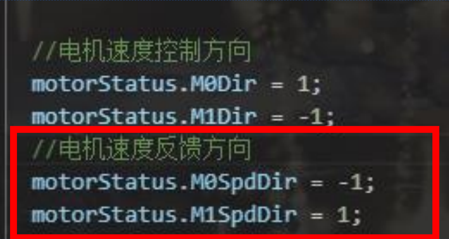
If the explanation above is still unclear, refer to the simplified rules below:
If the wheel turns forward and Vofa shows a negative value, invert the feedback dir.
If the wheel turns forward and Vofa shows a positive value, do not change the feedback dir.
If the wheel turns backward and Vofa shows a positive value, invert the feedback dir.
If the wheel turns backward and Vofa shows a negative value, do not change the feedback dir.
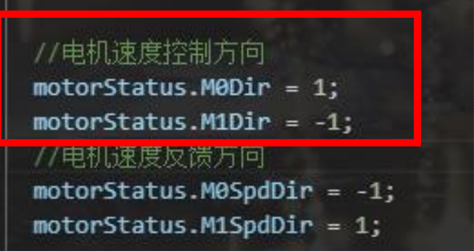
4. Set Motor Control dir (search motors.setTargets)
Uncomment the motor-control line as shown in the image and comment out the line below it, then flash the program.
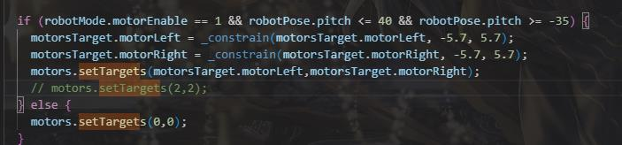
Power on the robot. After the reset is complete, tilt the robot forward while holding it. If both wheels rotate forward, the balance direction is correct.
If the left wheel turns backward, invert M1Dir. The right wheel is adjusted the same way.
After completing these steps, the robot can now be controlled. The following describes how to operate it. You can also refer to the document StackForce Wheeled_Legged_Robot Basic Operation Manual (PDF).
Front-side joysticks:
-
Step 1: Set the left-top switch to
middle, the right-top switch todown, and the left-bottom stick tolowest. Hold the robot, let the legs hang naturally, keep the wheels off the ground, and keep the body level.Power on, wait about
10 seconds, then place the robot on the ground and keep it upright. -
Step 2: Set the right-top switch to
middle, push the left-bottom stickslightly up, and set the left-top switch toup. The robot enters self-balancing mode.Use the right-bottom stick
forward/backto move forward/backward andleft/rightto turn left/right.Use the left-bottom stick
up/downto adjust leg height.When the right-top switch is at
top, move the left-bottom stickleft/rightto control roll. Power off to exit roll mode.
Live Demo
(Actual demo video to be added)
Citation
StackForce Wheeled_Legged_Robot Basic Operation Manual (PDF)
Mini-Wheeled-legged robot installation document.pdf
Full set of control board schematics
Example projects for the development kit
Customer registration code acquisition
Wheeled-Legged Robot Tool Pack
Tech Support & Product Discussion
Thank you for choosing our products! We are here to provide you with different support to ensure that your experience with our products is as smooth as possible. We offer several communication channels to cater to different preferences and needs.