Stackforce X Series Motors Getting Start
This article will introduce how to get started with Stackforce series motors and how to use them with C++ and Python on the reComputer Jetson Super.
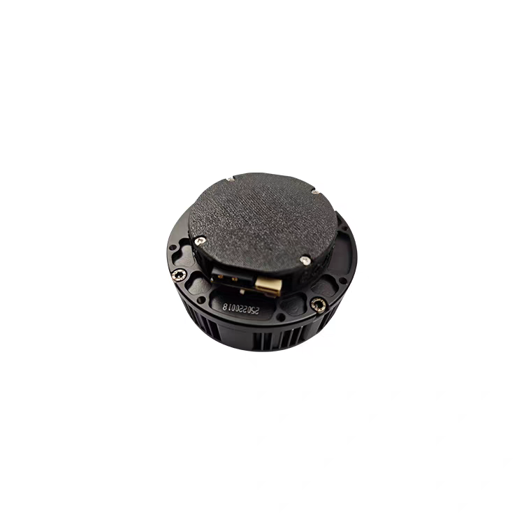
Specification
Here's the completed table with all parameters filled in for all motor models:
| Parameter | 6010 | 8108 |
|---|---|---|
| Rated Voltage | 24V | 24V |
| Rated Current | 10.5A | 7.5A |
| Rated Power | 240W | 180W |
| Rated Torque | 5 Nm | 7.5 Nm |
| Peak Torque | 11 Nm | 22 Nm |
| Rated Speed | 120 RPM | 110 RPM |
| Maximum Speed | 270 RPM | 320 RPM |
| Gear Ratio | 8:1 | 8:1 |
| Communication protocol | MIT Protocol | MIT Protocol |
| Control Modes | Position, Velocity, Torque Control | Position, Velocity, Torque Control |
| Outer Diameter | 80 mm | 97 mm |
| Thickness | 47 mm | 46 mm |
| Weight | 392 g ±10% | 395 g ±5% |
| Phase Resistance | 0.48 Ω ±10% | 0.439 Ω ±10% |
| Phase Inductance | 368 μH ±10% | 403 μH ±10% |
Main Features
- High Torque Output
- MIT Mode Control
- Magnetic Encoder Feedback
- Compact and Lightweight Design
- Support for High-Speed CAN Bus Communication
- Versatile Applications
Getting Started Guide
Preparations Before Use
On a PC with Windows System
- Product Manual.
- Download VOFA.
The motor’s CANID and CANMode are both modified via serial port. The motor is shipped with a default CANID of 0x01 and CANMode of CAN2.0 at 1Mbps.
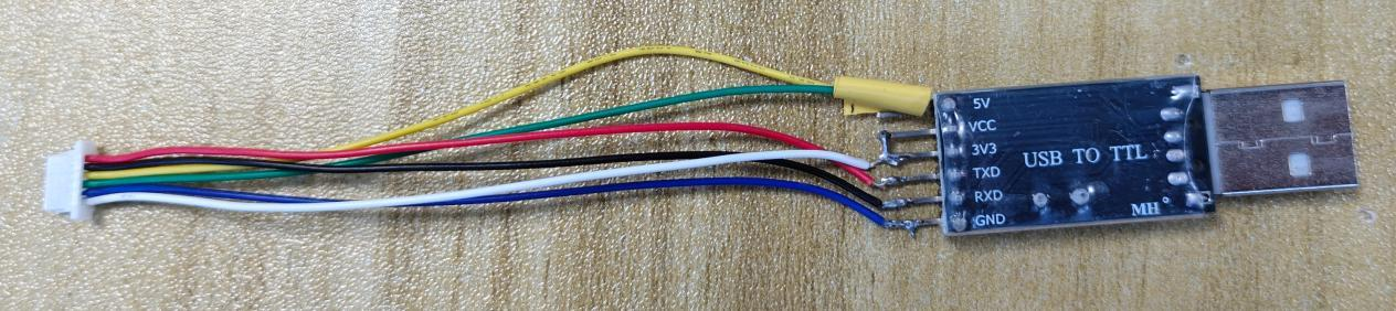
Serial Port Wiring
Connect V, G, T, R to the VCC (3.3V), GND, RX, TX of the serial communication module respectively (RX and TX should be cross-connected). As shown in the figure below:
Modifying CANID
Set the serial port baud rate to 1Mbps.
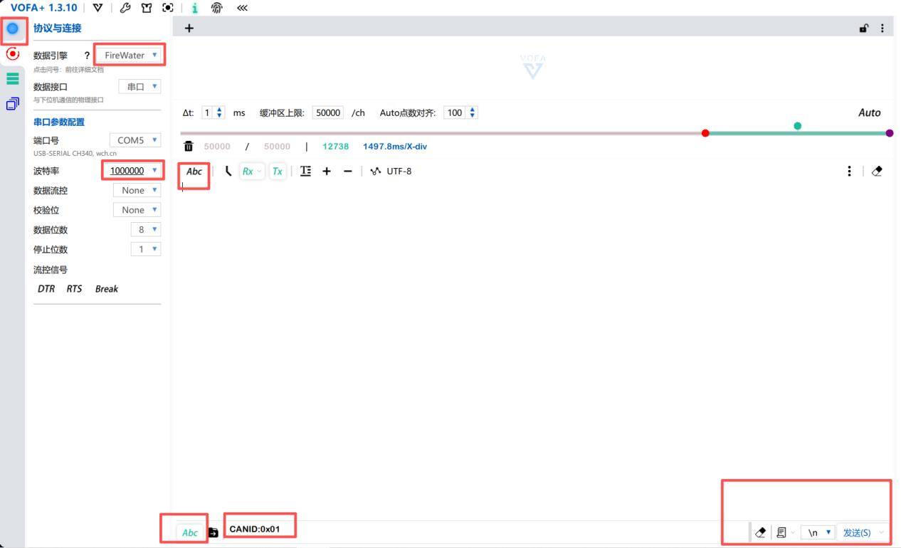
The CANID to be sent is 0x**, and the set ID is 0x**, with a maximum limit of 0x7F. After successfully setting the CANID, the following log will be printed:
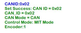
You can set the CANID:0x01 for easier testing in the subsequent code.
Modifying CAN Mode
Send CANMODE:0 or CANMODE:1 via the serial port.
CANMODE:0 represents CAN2.0 mode (1Mbps), while CANMODE:1 represents CANFD mode (5Mbps).
Successful modification of CAN mode is shown in the figures below:
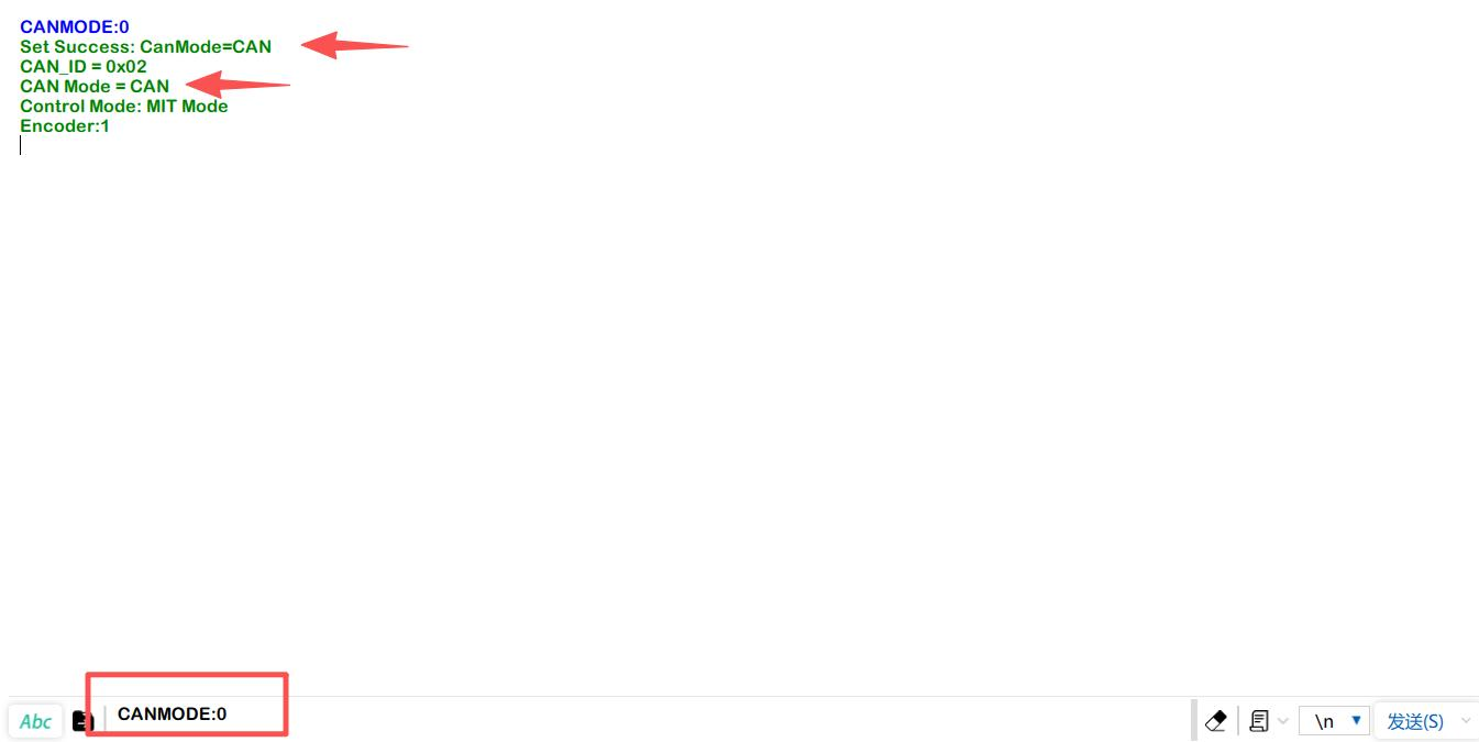
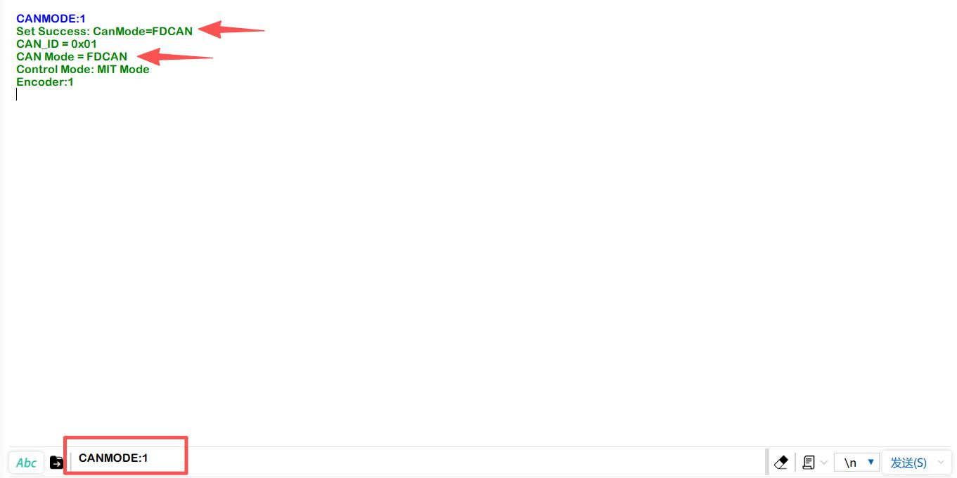
You can set the CANMODE:0 for easier testing in the subsequent code.
Using reComputer Mini Jetson Orin to Control Motors
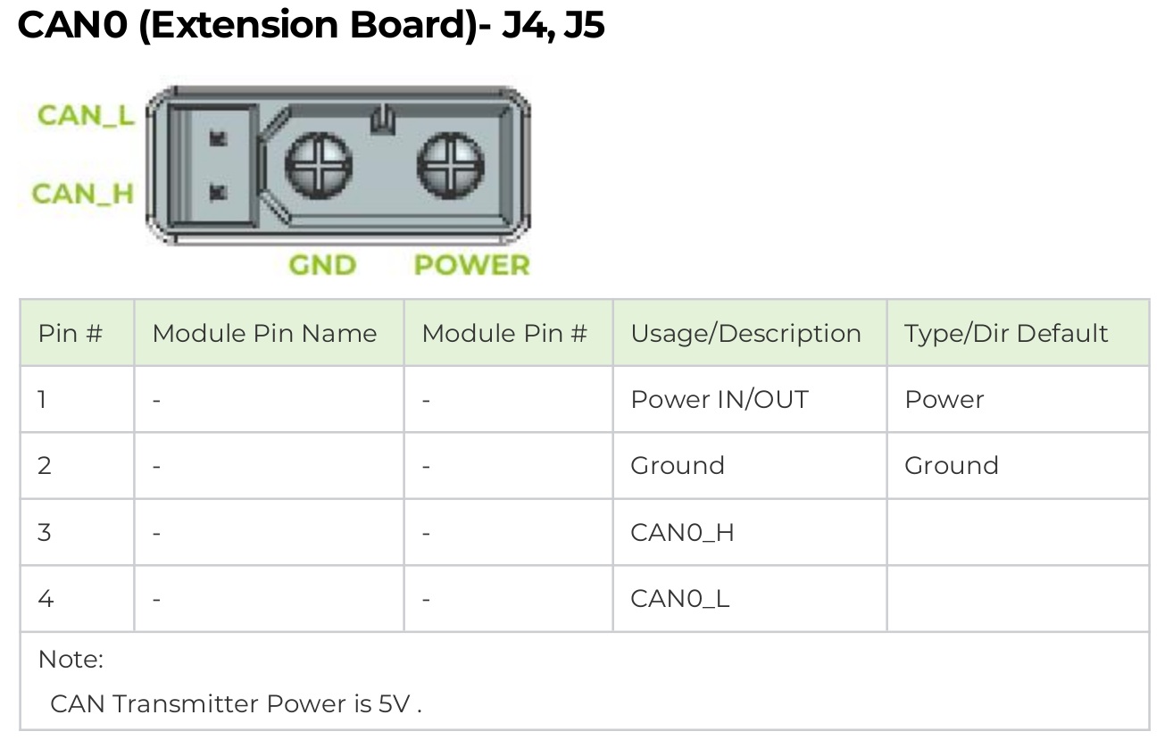
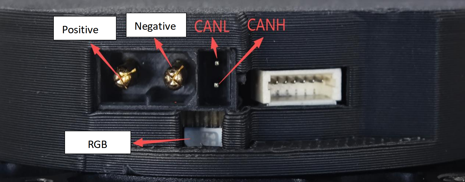
The most common CAN communication interfaces for motors on the market are XT30 (2+2) and JST connectors. Our reComputer Mini Jetson Orin and reComputer Robotics devices are equipped with dual XT30 (2+2) interfaces and CAN interfaces based on JST, providing seamless compatibility.
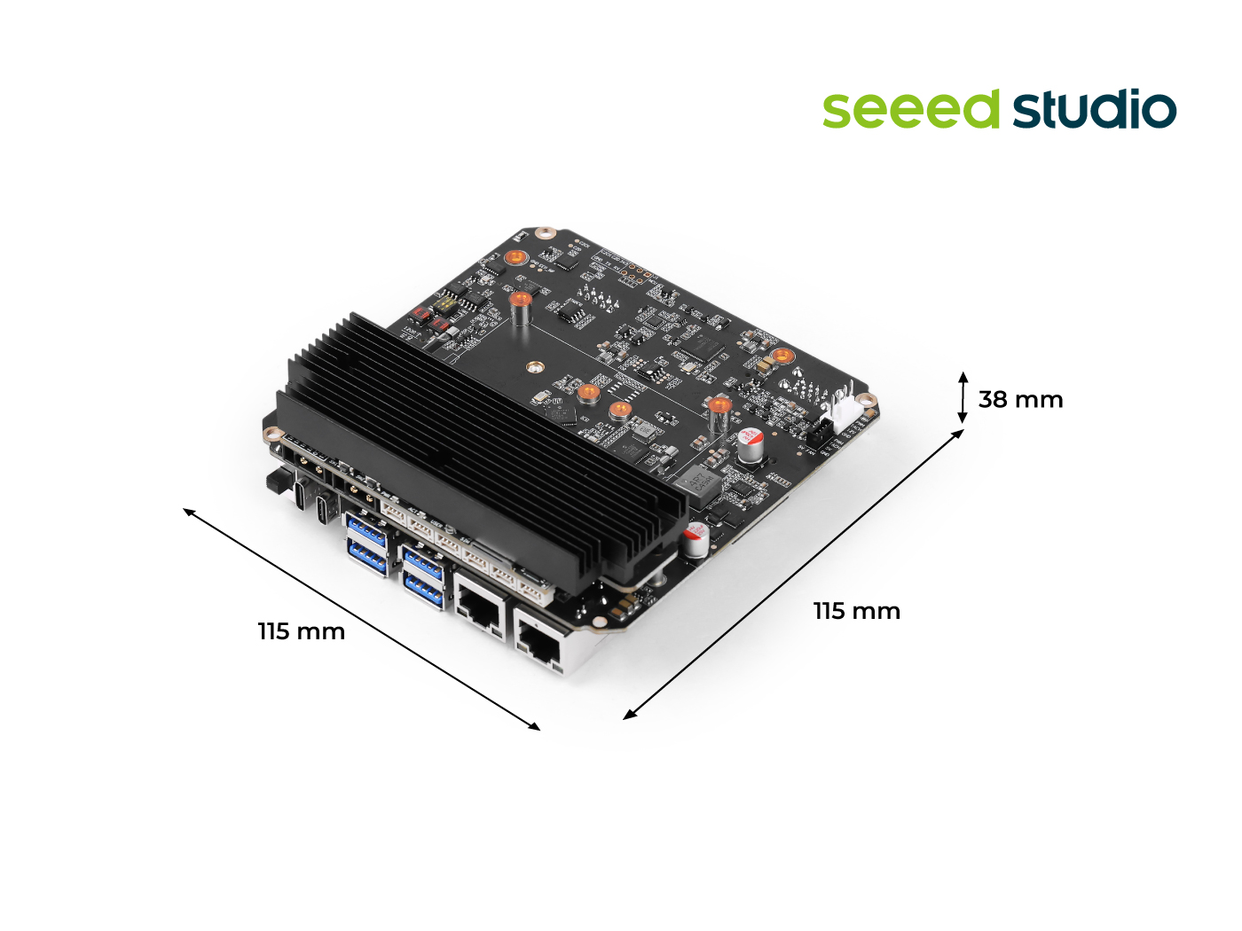
reComputer Mini:

reComputer Robotics
For more detailed information on CAN usage, please refer to this wiki.
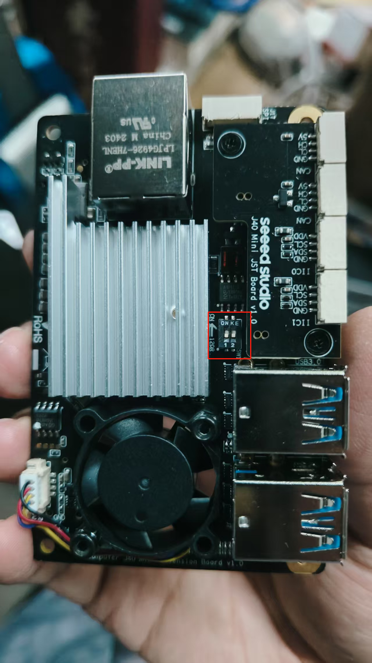
Enabling CAN Interface
Step 1: Before using CAN0 and CAN1, please remove the bottom cover and set the two 120Ω terminal resistors to the ON position.
Turn off the toggle switch of the 120Ω CAN communication terminal resistor integrated on the motor.
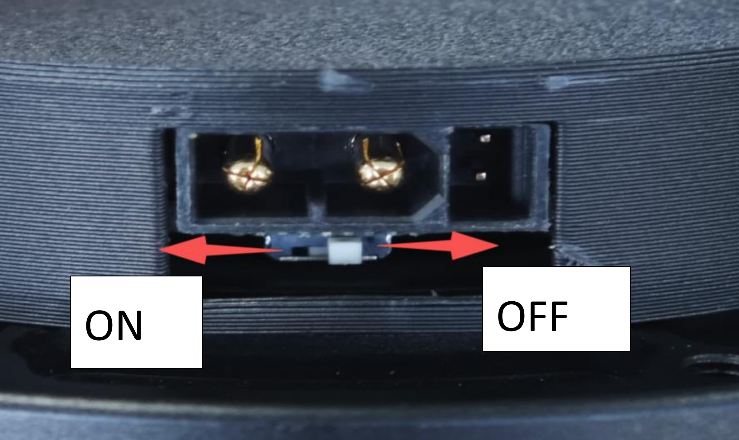
If the Recomputer Mini has not set the 120Ω terminal resistor to ON, you can choose to turn on the toggle switch of the motor's CAN communication terminal resistor.
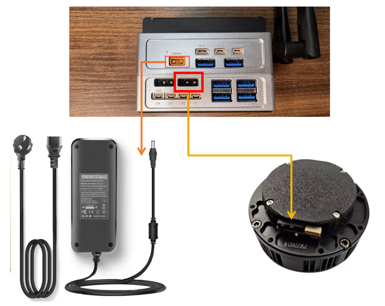
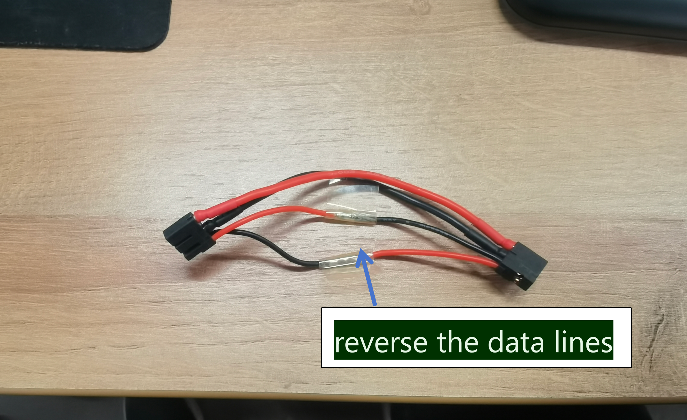
Step 2: Connect the motor directly to the CAN0 of the reComputer Mini via the XT30 (2+2) interface.
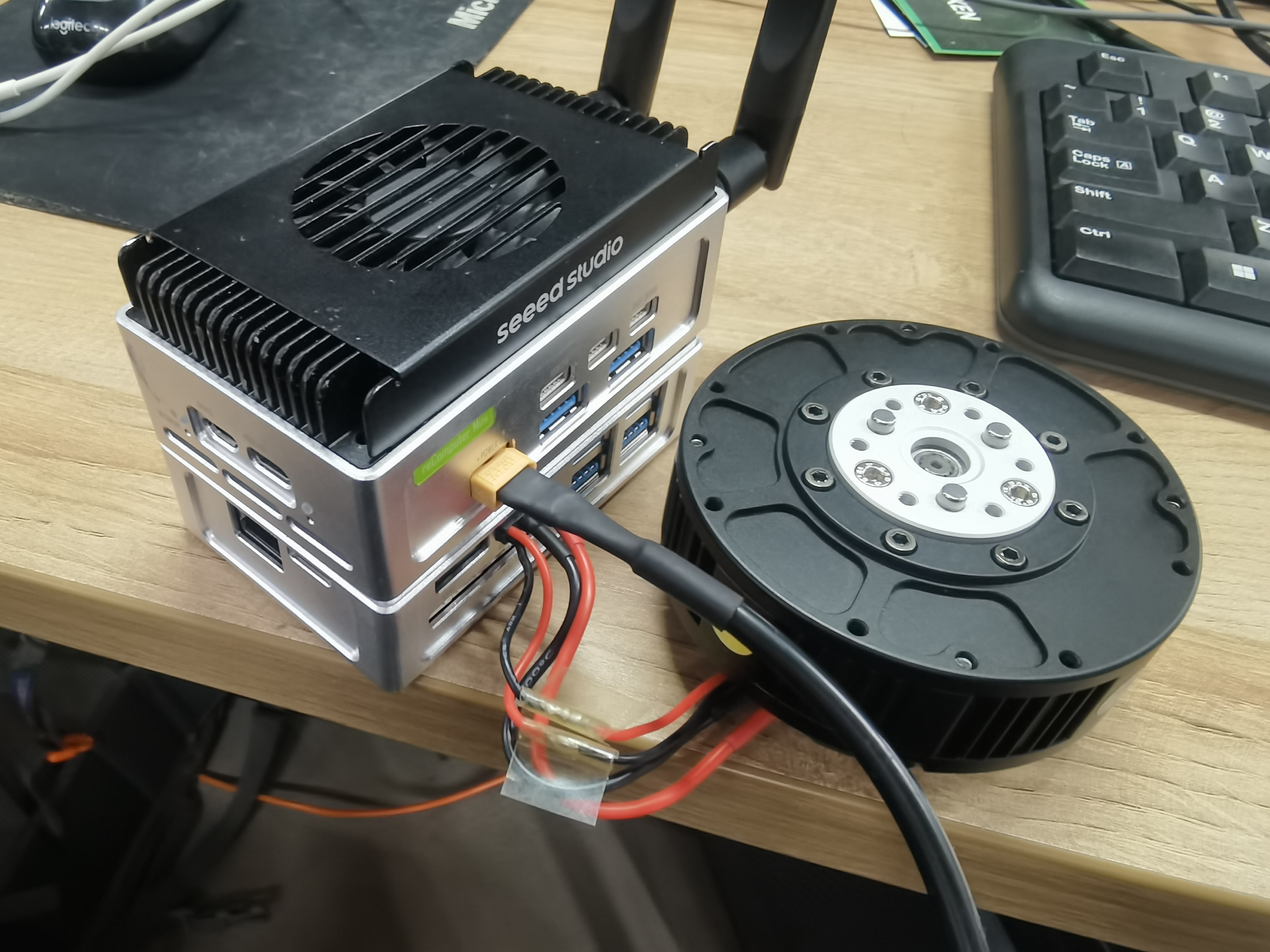
Since the CAN interface design of the reComputer Mini is opposite to that of the motor’s CAN interface, manual soldering is required to reverse the data lines.
Considering the high voltage and current required by the motor, it is recommended to purchase a 24V 300W power adapter to power the reComputer Mini for driving a single motor. If more motors need to be connected, a higher-power power adapter can be purchased according to the requirement.

This power supply is only for single-motor learning and testing. For multiple motors, please design a separate power board and isolate the power supply of Jetson from the motor power supply to avoid high current passing directly through Jetson.
Enabling Jetson CAN Communication
Open a terminal and enter the following command to pull the GPIO pin high to activate CAN0:
gpioset --mode=wait 0 43=0
If using CAN1 with the JST interface, pull pin 106 high.
gpioset --mode=wait 0 106=0
Keep this terminal open, start a new terminal, and configure CAN0.
sudo modprobe mttcan
sudo ip link set can0 type can bitrate 1000000
sudo ip link set can0 up
Setting Up C++ and Python Environment
Step 1: Clone the SDK.
git clone https://github.com/Seeed-Projects/Stackforce-Motor-SDK.git
Step 2: The driver SDK requires the following dependencies. For Debian Linux, they can be installed via the following commands:
sudo apt-get install -y build-essential cmake
sudo apt install linux-modules-extra-5.15.0-1025-nvidia-tegra # For Jetson Jetpack 6.0
If Python bindings are needed, additionally install Python 3, pip, and pybind11:
sudo apt-get install -y python3 python3-pip python3-pybind11 python3-setuptools
After installing the dependencies, follow the steps below to install the driver SDK as a C++ library or a Python package. Both will use CMake to compile the C++ code.
Motor Control and Data Receive
C++
main.cpp
#include <chrono>
#include <cstdint>
#include <cmath>
#include <cstdio>
#include <thread>
#include "CAN_comm.h"
#include "config.h"

MIT devicesState[4];

uint32_t sendNum; // for testing send speed
uint32_t recNum;

MIT MITCtrlParam;

uint16_t sendCounter = 0;
bool motorEnable = true;
int receivedNumber = 0;
uint64_t prev_ts = 0;
float t = 0.0f;
float targetJointAngle = 0.0f; // Target joint angle (can be modified at runtime via input)

namespace {
uint64_t micros_steady(){
  using namespace std::chrono;
  return duration_cast<microseconds>(steady_clock::now().time_since_epoch()).count();
}
}

void setup() {
  std::printf("SF Motor Control (Jetson) start\n");
  CANInit();
  enable(0x01); // Enable motor with ID 0x01  <- Change ID to control different motors
  prev_ts = micros_steady();
  t = 0.0f;
}

uint16_t printCount = 0;
uint16_t recCount = 0;

void loop() {

  recCANMessage();

  // Check for new joint angle input
  // (Check once every 1000 loops to avoid frequent blocking input calls)
  static uint16_t inputCheckCount = 0;
  if(++inputCheckCount >= 1000){
    inputCheckCount = 0;
    float newAngle;
    if(std::scanf("%f", &newAngle) == 1){
      targetJointAngle = newAngle;
      std::printf("Target joint angle updated: %.3f rad\n", newAngle);
    }
  }

  static int IDswitch = 0x01; // <- Change ID to control different motors
  uint64_t current_ts = micros_steady();

  /*
   * Function:
   *   Update control parameters based on time difference and send MIT command.
   *
   * Parameters:
   *   - current_ts: current timestamp
   *   - prev_ts   : previous timestamp
   *   - t         : time variable used for sine/cosine calculations
   *   - MITCtrlParam:
   *       Control parameter structure including position, velocity,
   *       position gain (Kp), velocity gain (Kd), and torque
   *   - IDswitch  : motor ID selector
   *
   * Return:
   *   None
   */
  if(current_ts - prev_ts >= 1000){ // 1 ms control period
    // Update time variable (increase by 1 ms)
    t += 0.001;

    // Set control parameters:
    // target position, target velocity, position gain, velocity gain, and torque
    MITCtrlParam.pos = targetJointAngle;
    MITCtrlParam.vel = 0;
    MITCtrlParam.kp  = 0.5;
    MITCtrlParam.kd  = 0.3;
    MITCtrlParam.tor = 0;

    // Update previous timestamp
    prev_ts = current_ts;

    // IDswitch++;
    // If IDswitch exceeds 0x04, reset it to 0x01
    // if(IDswitch > 0x04){
    //   IDswitch = 0x01;
    // }

    sendMITCommand(IDswitch, MITCtrlParam); // Send MIT command

    printCount++;
    if(printCount >= 100){
      printCount = 0;
      // Only print when IDswitch is 0x01
      // Print commanded position/velocity and actual motor position/velocity
      if(IDswitch == 0x01){
        std::printf( "[CMD] pos: %6.3f rad vel: %6.3f rad/s | " "[FB] pos: %6.3f rad vel: %6.3f rad/s\n", MITCtrlParam.pos, MITCtrlParam.vel, devicesState[IDswitch - 1].pos, devicesState[IDswitch - 1].vel );
      }
    }
  }

  std::this_thread::sleep_for(std::chrono::milliseconds(1));
}

int main(){
  setup();

  while(true){
    loop();
  }

  disable(0x01); // Disable motor with ID 0x01
  return 0;
}
cd build
cmake ..
make
The compiled executable will be located at build/sfmotor_control. Run the program:
./sfmotor_control
The program defaults to controlling the motor with ID 0x01. During operation, you can input the target angle value (in radians) via the keyboard. It also receives feedback data on the motor’s angle and angular velocity.
Python
main.py
import sys
import time
import select

# Import core control module (assumes sf_can_controller.py is in the same directory)
from sf_can_controller import MotorController

# --- Core Configuration ---
IFACE = "can0"
MOTOR_ID = 1         # <- Change ID to control different motors
UPDATE_RATE_HZ = 100.0
PRINT_EVERY = 2
INITIAL_TARGET_DEG = 0.0

# --- Main Control Loop ---
def run_simple_test() -> None:
    """Run a simplified position control loop."""

    # 1. Initialization
    update_period = 1.0 / UPDATE_RATE_HZ
    target_rad = INITIAL_TARGET_DEG

    KP, KD = 0.5, 0.3  # Default MIT parameters

    controller = MotorController(interface=IFACE, motor_id=MOTOR_ID)
    print(f"--- SF Motor Test Start ---")
    print(f"Interface: {IFACE}, ID: {MOTOR_ID}, Rate: {UPDATE_RATE_HZ} Hz")

    # 2. Enable motor
    controller.enable()

    last_send_time = time.perf_counter()
    print_counter = 0

    inputCheckCount = 0

    # 3. Main loop
    while True:
        controller.poll_rx()
        current_state = controller.get_motor_state()

        now = time.perf_counter()

        # --- Periodic input check (every 500 loops) ---
        inputCheckCount += 1
        if inputCheckCount >= 500:
            inputCheckCount = 0

            # Blocking I/O waiting for user input (this will pause the control loop)
            # Note: If the input is not a number, a ValueError will be raised.
            line = input("Please enter target joint angle: ").strip()
            if line:
                angle_deg = float(line)
                target_rad = angle_deg
                print(f"Target joint angle updated: {angle_deg:.3f} deg")

        # Periodically send MIT command
        if now - last_send_time >= update_period:
            last_send_time = now

            # Send target position command
            controller.send_mit_command(
                pos=target_rad,
                vel=0.0,
                kp=KP,
                kd=KD,
                tor=0.0
            )

            # Print motor state
            print_counter += 1
            if print_counter >= PRINT_EVERY:
                print_counter = 0
                print(
                    f"Cmd={target_rad:.2f} | "
                    f"Pos={current_state.pos:.2f} (Vel={current_state.vel:.2f})"
                )

        time.sleep(0.001)


if __name__ == "__main__":
    # Run test
    run_simple_test()
The Python script is located in the script/ directory and can be run directly without compilation.
python main.py
The program defaults to controlling the motor with ID 0x01. During operation, you can input the target angle value (in radians) via the keyboard. It also receives feedback data on the motor’s angle and angular velocity.
Citation
Tech Support & Product Discussion
Thank you for choosing our products! We are here to provide you with different support to ensure that your experience with our products is as smooth as possible. We offer several communication channels to cater to different preferences and needs.