Wio-LR2021 Dev Kit Factory Firmware User Guide
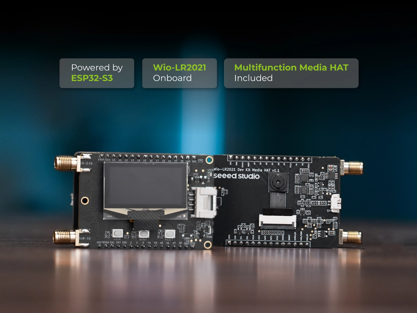
Every Wio-LR2021 Dev Kit ships with a test firmware that exposes the board's radios, sensors, display, camera, audio path and flash over one serial console. This guide takes you from first power-on to a full functional check, and it states what a pass looks like at every step.
The firmware on your board is the authority for this page. Type help to list the commands that the build actually registered; if a command here is missing, your board runs a different version.
What the firmware commands provide
- Sub-GHz and 2.4 GHz links:
lora_txwithlora_rxon two boards; the receiver count rises. - Modulation modes:
gfsk_tx,flrc_rx,lr_fhss_tx; good packets and CRC errors counted. - RF power:
lora_cw; a meter shows the carrier. - BLE —
ble -a 1; a scanner listswio-lr2021-*. - Wi-Fi and IP:
sta_connect,ap_set,ping;got ip:and reply counts. - GPIO, I²C and rails:
gpio_get,i2c_scan,io_exp_print;0x21and0x3Danswer. - Battery:
battery_get; millivolts and a charge estimate. - Display, camera, audio:
oled_test,camera_capture,audio_slot_play; pattern,PASS, playback. - Flash:
flash_info,flash_speed; return code0means pass.
Preparation
Step 1. Fit the antennas and connect the board
Screw the sub-GHz antenna onto SUB-1G and the 2.4 GHz antenna onto LR-2.4G. Connect USB-C with a data cable — a charge-only cable powers the board but gives no serial port.
Never transmit without an antenna. The PA drives up to +22 dBm on sub-GHz and +12 dBm on 2.4 GHz into a mismatched load, which can damage the LR2021.
Step 2. Find the serial port
- Windows
- macOS
- Linux
Open Device Manager and expand Ports (COM & LPT). The board appears as USB Serial Device with a port such as COM5.
ls /dev/cu.*
Look for /dev/cu.usbmodem*.
ls /dev/ttyACM*
The board is usually /dev/ttyACM0. If the port will not open, add your user to dialout.
Step 3. Open a terminal
| Tool | Platform | Where to get it |
|---|---|---|
| PuTTY | Windows | putty.org |
| screen | macOS / Linux | Built in; run screen /dev/cu.usbmodem* 115200 |
| Minicom | macOS / Linux | Install via the package manager; run minicom -D /dev/ttyUSB* -b 115200 |
Every tool needs the same line settings:
| Setting | Value |
|---|---|
| Baud rate | 115200 |
| Data bits | 8 |
| Parity | None |
| Stop bits | 1 |
| Flow control | None |
Step 4. Confirm the prompt
Press Enter. The board answers with its prompt:
cmd>
Type help to list every registered command.
cmd> help
Quick Start
1. List the commands
cmd> help
2. Read the battery
cmd> battery_get
I (737306) bsp_battery: calibration scheme version is Curve Fitting
I (737306) bsp_battery: Calibration Success
I (737386) bsp_battery: VBAT channel=7 raw_max=0 sense=0 mV battery=0 mV
I (737516) bsp_battery: VBAT channel=7 raw_max=2362 sense=2068 mV battery=4136 mV
I (737516) SENSOR_TEST: Battery probe: BAT_ADC_EN=0 -> 0 mV, BAT_ADC_EN=1 -> 4136 mV
I (737516) SENSOR_TEST: Battery voltage: 4136 mV, estimated level: 92%
It reports cell voltage in millivolts and a charge estimate. With no battery fitted the reading tracks the USB supply.
3. Transmit one LoRa packet
Fit the Sub-GHz antenna on SUB-1G before you transmit. Keep the board a meter away from other antennas while it runs.
cmd> lora_tx -f 868000000 -d hello -n 1
I (922806) LR20XX: Power          = 10 dB
I (922806) LR20XX: Frequency      = 868000000 Hz
I (922806) LR20XX: SF             = RAL_LORA_SF7
I (922806) LR20XX: BandWidth      = RAL_LORA_BW_125_KHZ
I (922806) LR20XX: CodingRate     = RAL_LORA_CR_4_5
I (922816) LR20XX: CRC            = 1
I (922816) LR20XX: IQ             = 0
I (922816) LR20XX: SyncWord       = 0x34
I (922816) LR20XX: LDO            = 0
I (922816) LR20XX: Interval       = 0
I (922816) LR20XX: Num            = 1
I (922816) LR20XX: half_power     = 0
I (922816) LR20XX: duty_cycle     = 0
I (922816) LR20XX: lf_slices      = 0
I (922816) LR20XX: is_config_pa   = 0
I (922816) LR20XX: tx len 5, payload: hello
I (922836) LR20XX: Starting LoRa TX #0
I (922876) LR20XX: LoRa tx done

I (923886) LR20XX: End of send!
4. Receive Sub-GHz packets
cmd> lora_rx -f 868000000 -s 7 -b 3
I (47044) LR20XX: Frequency      = 868000000 Hz
I (47044) LR20XX: SF             = RAL_LORA_SF7
I (47044) LR20XX: BandWidth      = RAL_LORA_BW_125_KHZ
I (47044) LR20XX: CodingRate     = RAL_LORA_CR_4_5
I (47044) LR20XX: Header_type    = RAL_LORA_PKT_EXPLICIT
I (47044) LR20XX: CRC            = 1
I (47044) LR20XX: IQ             = 0
I (47044) LR20XX: SyncWord       = 0x34
I (47044) LR20XX: LDO            = 0

W (82904) LR20XX: rx_done 0
W (82904) LR20XX: rx_hdr_err 0
W (82904) LR20XX: rx_crc_err 0

I (82904) LR20XX: End of receive!
Run the lora_rx -f 868000000 -s 7 -b 3 command on board A, the lora_tx -f 868000000 -s 7 -b 3 -p 14 -d hello -n 10 on board B. A's counter rises with each packet and B returns after ten. Stop A with Ctrl+C to print the totals. A count stuck at zero means the boards disagree on a radio setting, or an antenna is missing. Keep -i at 200 or above, or the receiver logs hdr err lines.
End the test with Ctrl+C on both boards, so neither stays in receive mode.
5. Wi-Fi station and ping
cmd> sta_connect <ssid> <pass>
cmd> ping 192.168.1.1 -c 4
The join succeeded when a line containing got ip: appears.
6. Camera over the hotspot
cmd> camera_start
cmd> camera_http_start
Join wio-lr2021-camera with the password 12345678 and open http://192.168.4.1. Live frames prove the camera and the Wi-Fi stack at once.
End the test with camera_http_stop and camera_stop, then rejoin your normal network.
7. Draw a display pattern
cmd> oled_test -m text
I (2177034) bsp_oled_ssd13xx: OLED initialized (128x64, addr 0x3d)
I (2177064) OLED_TEST: OLED test pattern displayed: text
cmd> oled_test -m checker
I (2262024) OLED_TEST: OLED test pattern displayed: checker
cmd> oled_test -m clear
I (2316714) OLED_TEST: OLED test pattern displayed: clear
8. Record and play audio
audio_slot_record -d 5000
audio_slot_play
9. Identify the flash chip
cmd> flash_info
I (2491984) FLASH_TEST: ==== SPI flash identification ====
I (2491984) FLASH_TEST:  JEDEC ID        : 0xEF4018
I (2491984) FLASH_TEST:  Manufacturer    : 0xEF (Winbond)
I (2491984) FLASH_TEST:  Memory type     : 0x40
I (2491984) FLASH_TEST:  Capacity (ID)   : 0x18 => 16777216 bytes (16.00 MB)
I (2491984) FLASH_TEST:  Physical size   : 16777216 bytes (16.00 MB)
I (2491984) FLASH_TEST:  Configured size : 16777216 bytes (16.00 MB)
I (2491984) FLASH_TEST:  Partition "flashtest" : addr=0x00C10000 size=1048576 (1.00 MB) subtype=0x06
I (2491984) FLASH_TEST: ==== Tail boundary authentication ====
I (2491994) FLASH_TEST:  head sector off=0x00000000, tail sector off=0x000FF000
I (2492114) FLASH_TEST:  head verify : PASS
I (2492124) FLASH_TEST:  tail verify : PASS
I (2492124) FLASH_TEST:  boundary auth: PASS
Behavior and Limits
| Behavior | Commands | What happens | How to exit |
|---|---|---|---|
| Continuous receive | lora_rx, flrc_rx | Counts packets, no prompt | Ctrl+C |
| Endless transmit | lora_tx -n 0, flrc_tx -c 0 | Sends without a stop | Ctrl+C |
| Continuous wave | lora_cw, lora_cw_pa | Unmodulated carrier, no payload | lora_cw_stop |
| Background task | flash_endurance -a start | Returns at once, keeps erasing | flash_endurance -a stop |
| Hotspot lifetime | ap_set, camera_http_start, audio_slot_send | Radio stays up until closed | wifi stop, camera_http_stop, audio_slot_stop |
- One command owns the console: during a receive or transmit loop the firmware ignores input.
- Output is plain text; enable terminal logging for a test record.
- Some terminals bind
Ctrl+Cto copy; confirm yours sends the interrupt.
Safety and Compliance
1. One antenna per band. The SMA connector and the U.FL pad of a band share one RF net through a 0 Ω link. Fitting both leaves neither antenna matched.
2. Never leave a carrier running. lora_cw and lora_cw_pa transmit a continuous carrier with no payload. Stop them with lora_cw_stop before moving the board.
3. Check your band plan. Sub-GHz output reaches +22 dBm and 2.4 GHz reaches +12 dBm. 868 MHz serves Europe, 902 ~ 928 MHz the Americas. Confirm your national limits, and use a shielded box for certification runs.
4. Battery and solar. Use one 3.7 V Li-ion cell on BAT-3.7V, observing the silkscreen polarity. The CN3165 charger delivers about 495 mA and has no thermistor input, so do not charge unattended.
5. Default credentials. The camera and audio hotspots ship with the password 12345678, and the camera page has no login. Change the password and close the hotspot on a shared bench.
6. Flash endurance wears the chip. flash_endurance erases real sectors of the flashtest partition. Run it on sample units only, never on a board you still need.
Resource
Tech Support & Product Discussion
Thank you for choosing our products! We are here to provide you with different support to ensure that your experience with our products is as smooth as possible. We offer several communication channels to cater to different preferences and needs.