Getting Started with Wio-LR2021 Dev Kit
Introduction
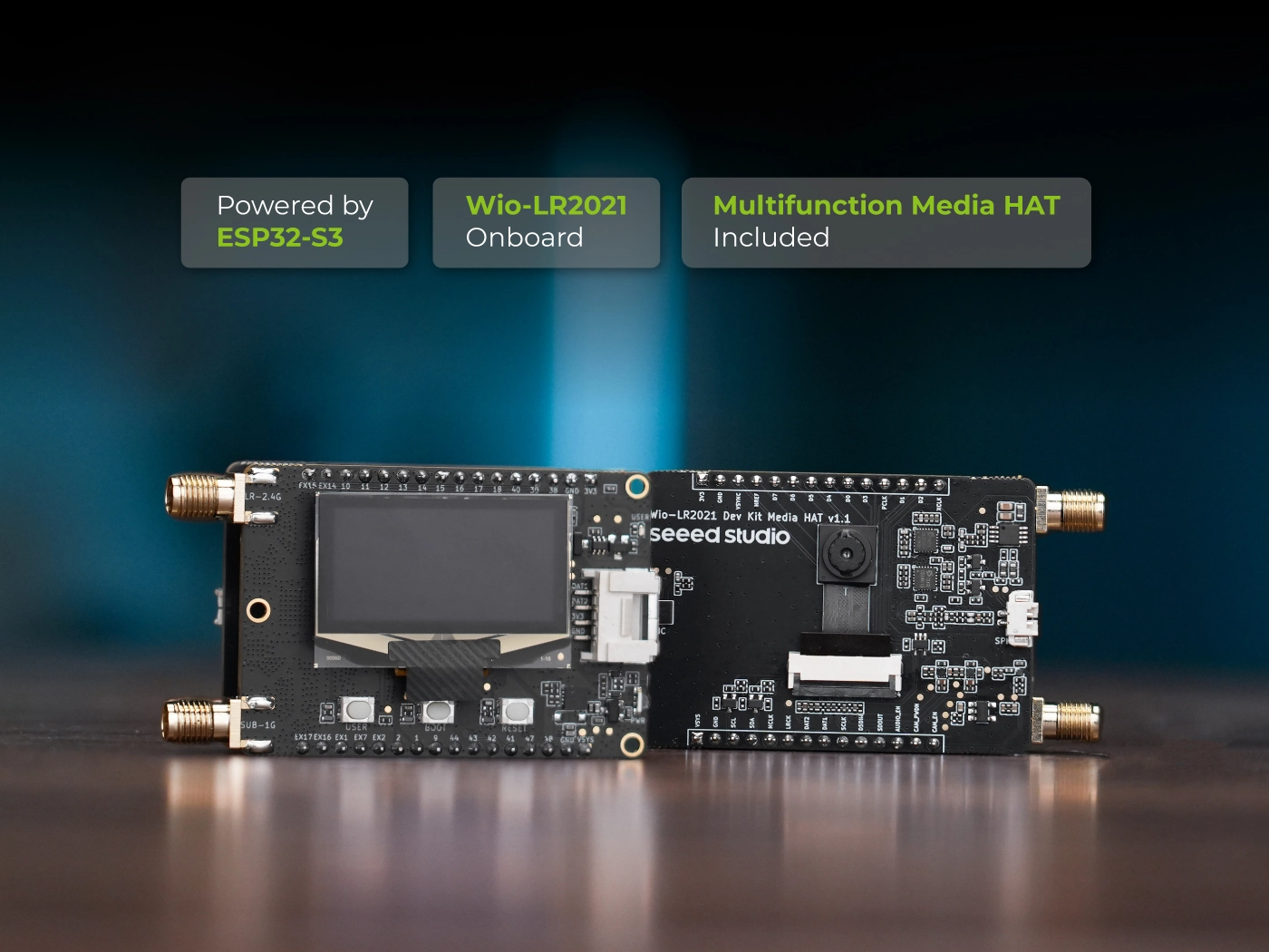
The Wio-LR2021 Dev Kit is a dual-band LoRa development kit that pairs Semtech's LR2021 transceiver with an ESP32-S3. The radio module covers from 150 ~ 960 MHz and the 2400 ~ 2500 MHz band from a single package, so one board can move between long-range links and worldwide channels in software. FLRC adds burst rates up to 2.6 Mbps for images and audio, and the ESP32-S3R8, with 8 MB PSRAM and 16 MB flash, can judge a camera frame before it reaches the air.
A detachable Media HAT carries a 2 MP GC2145 camera, a MEMS microphone, an ES8311 codec and an NS4150B amplifier with a speaker connector. On the main board you also get a 128 × 64 OLED, a PCA9535 expander that switches four peripheral power rails, a 3.7 V Li-ion and a 5 V solar input behind a CN3165 charger, a Grove port and two 16-pin headers.
The kit ships with a factory firmware, so you can check the radio, the camera, the display, the audio path and the battery from a terminal before writing any firmware.
Specifications
| Parameter | Value |
|---|---|
| MCU | ESP32-S3R8, dual-core Xtensa LX7 up to 240 MHz |
| RF transceiver | Semtech LR2021, integrated in the Wio-LR2021 module |
| Frequency bands | 150 ~ 960 MHz and 2400 ~ 2500 MHz |
| Modulation | LoRa (SF5 ~ SF12), (G)FSK, FLRC, LR-FHSS |
| Transmit power | up to +22 dBm (sub-GHz), up to +12 dBm (2.4 GHz) |
| Wi-Fi and Bluetooth | 802.11 b/g/n 2.4 GHz, Bluetooth 5 LE |
| Antenna connectors | 2 × SMA (sub-GHz, 2.4 GHz) plus 3 × U.FL |
| Type-C Interface | USB-C with native USB-Serial-JTAG, no bridge chip |
| Grove Interface | Grove port plus 2 × 16-pin 2.54 mm headers |
| Buttons and LEDs | USER, BOOT and RESET buttons; 1 power LED; 1 user LED |
| I/O expander | PCA9535, 16 I/O, I2C address: 0x21 |
| OLED | 128 × 64 monochrome, 0.96 inch, CH1116 driver, I2C address: 0x3D |
| Camera (HAT) | GC2145, 2 MP, 8-bit DVP interface |
| Audio (HAT) | ES8311 codec, NS4150B amplifier, MEMS microphone, speaker connector |
| Power Interface | USB-C 5 V, solar 5 V (JST), 3.7 V Li-ion (JST) |
| Charging IC | CN3165, 495 mA charge current |
| Regulators | TPS62A03 buck (3.3 V system), SGM2059 LDO (radio rail) |
| Dimensions | 55 × 38.5 mm main board, 55 × 38.5 mm Media HAT |
| Mounting Hole | 3 × M2 holes |
Features
- Dual-band radio: Sub-GHz and 2.4 GHz share one module, so a single design covers worldwide bands.
- Fast bursts: FLRC carries an image at up to 2.6 Mbps, then drops back to LoRa when range matters.
- On-device vision: 8 MB PSRAM buffers camera frames, so the radio sends a conclusion instead of pixels.
- Detachable media HAT: Camera, microphone, codec and amplifier ride two 16-pin connectors.
- Field power: A 5 V solar input and a 3.7 V Li-ion connector keep a node running off-grid.
- Switchable rails: The PCA9535 gates the camera, audio, OLED and Grove rails from software.
- Onboard display: A 128 × 64 OLED on the shared I2C bus shows readings or link state without extra hardware.
- Native USB: USB-Serial-JTAG needs no bridge chip, so flashing and the console share one cable.
Hardware Overview
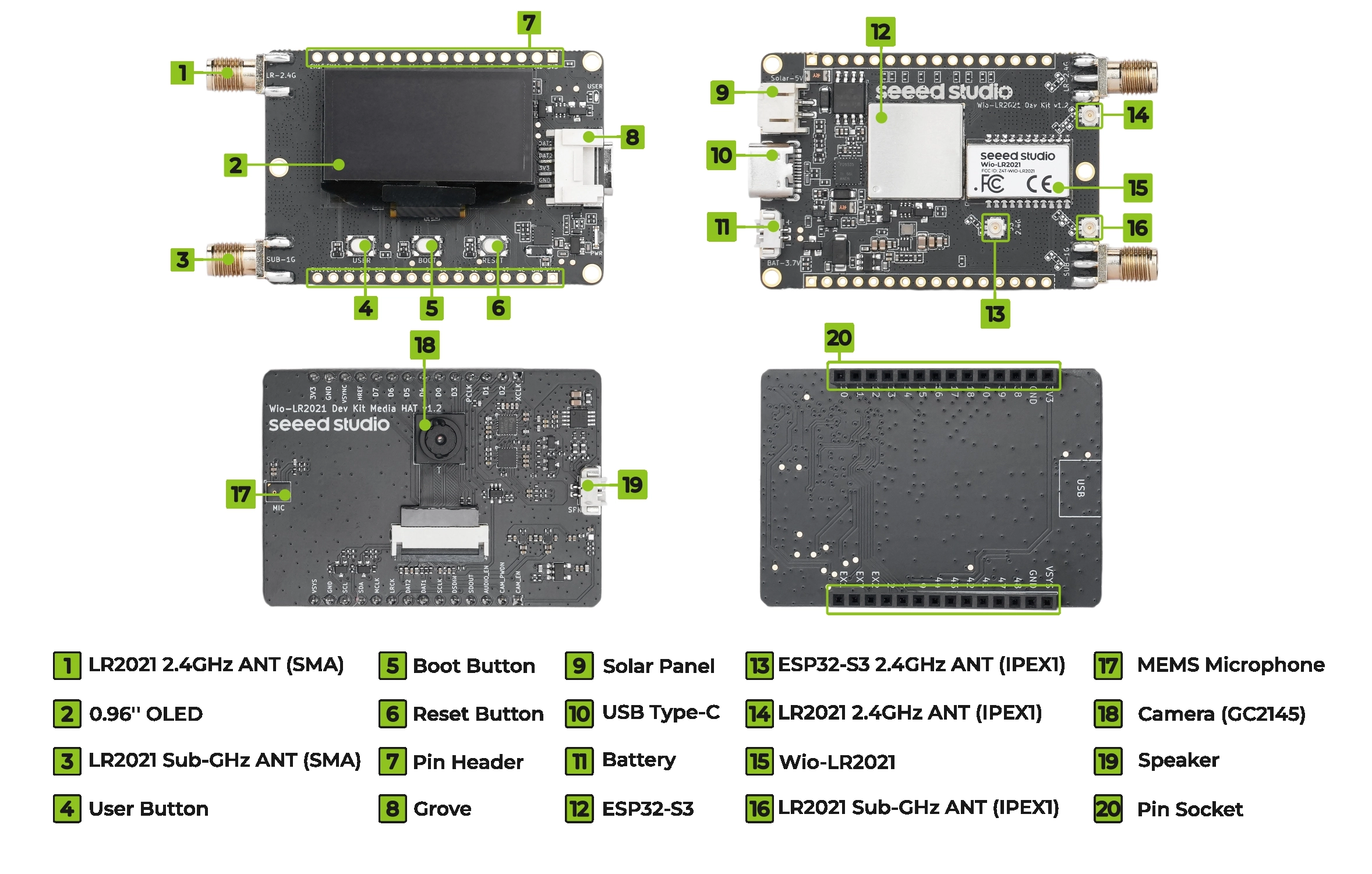
The kit has two boards that share a 55 × 38.5 mm footprint. The main board carries the radio, the display and the power path; the Media HAT adds the camera and the audio path.
Main Board Front
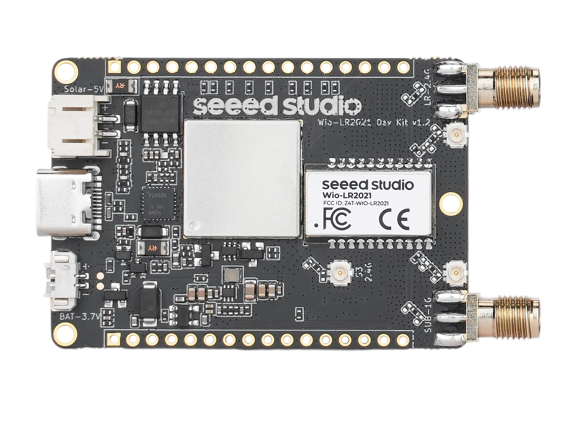
- ESP32-S3R8 with 16 MB SPI NOR flash
- Wio-LR2021 module carrying the LR2021 transceiver, with a 32 MHz TCXO integrated
- Sub-GHz SMA connector for the 150 ~ 960 MHz port
- 2.4 GHz SMA connector for the 2400 ~ 2500 MHz port
- Three U.FL pads: ESP32-S3 2.4 GHz, LR2021 2.4 GHz and LR2021 sub-GHz
- USB-C port with native USB-Serial-JTAG
- Solar input on a 2-pin JST connector, labelled
Solar-5V - Battery input on a 2-pin JST connector, labelled
BAT-3.7V - Two 16-pin 2.54 mm headers, one along each long edge
The SMA connectors and U.FL pads are connected to the same two RF nets through 0 Ω links. By default, the SMA connectors are enabled. To use the U.FL interface instead, please resolder the 0 Ω links to the corresponding alternative pads.
Main Board Back
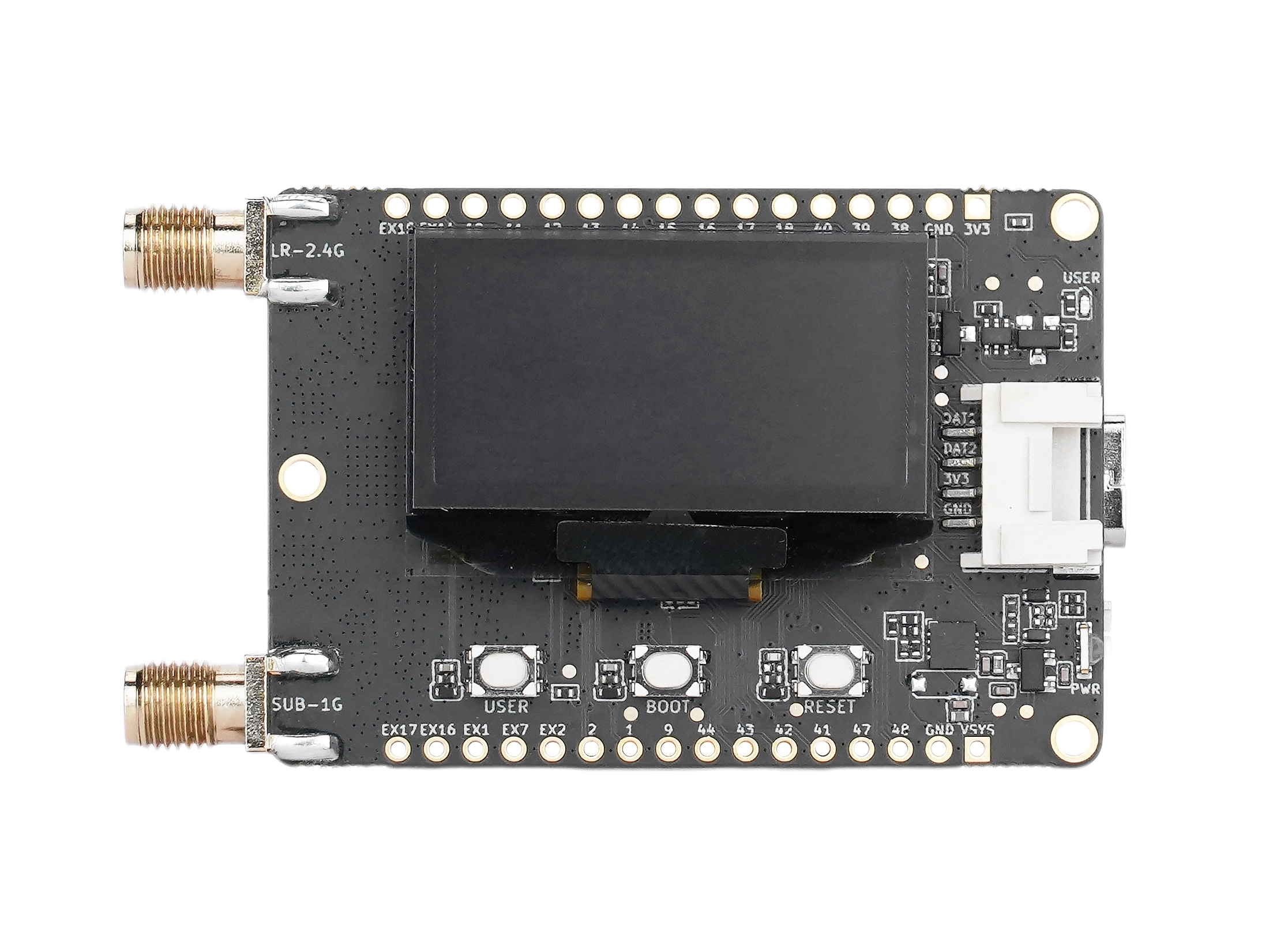
- 128 × 64 OLED, driven over I2C at address
0x3D - USER button on
GPIO46, with a 10 kΩ pull-up and a 100 nF debounce capacitor - BOOT button on
GPIO0, pulls the chip into the download mode if enabled at reset - RESET button, wired to the ESP32-S3 enable pin (active LOW)
- Grove connector, a 4-pin 2.0 mm standard socket
- User LED, controled by the
P06of the PCA9535 (active LOW) - Power LED, lit whenever the board has a live supply
The USER button sits on GPIO46, which is a strapping pin on the ESP32-S3. If the button is held while RESET is released, the chip samples a LOW level on that strap and enter the download mode instead of booting. Release the button before resetting.
Media HAT
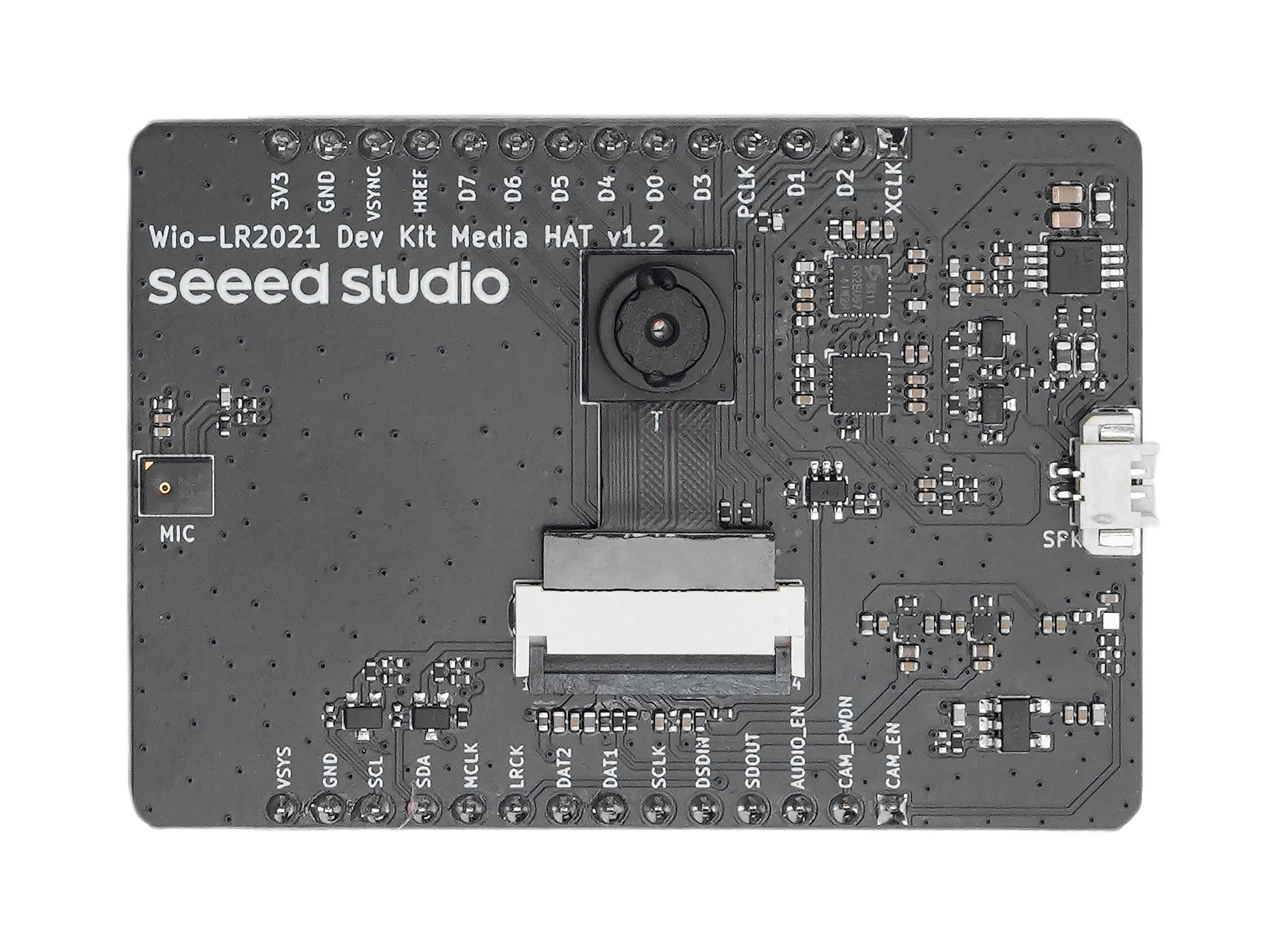
- GC2145 camera, 2 MP, connected over an
8-bit DVPbus on a 24-pin FPC - MEMS microphone with an analog output, wired to the codec
- ES8311 codec, I2S audio in and out, configured over I2C
- NS4150B Class-D amplifier driving the speaker connector labelled
SPK
Pin Map
The main board breaks out two 16-pin headers at 2.54 mm pitch. The Media HAT breaks out two 14-pin sockets at 2.54 mm pitch which are able to plug into both headers on the main board.
Since the Main Board uses a 16‑pin header while the Media Hat expansion board uses only a 14‑pin socket, careful attention MUST be paid to orientation during installation. Ensure that the pins are correctly ALIGNED. Incorrect installation may cause malfunction and could result in irreversible damage to the device.
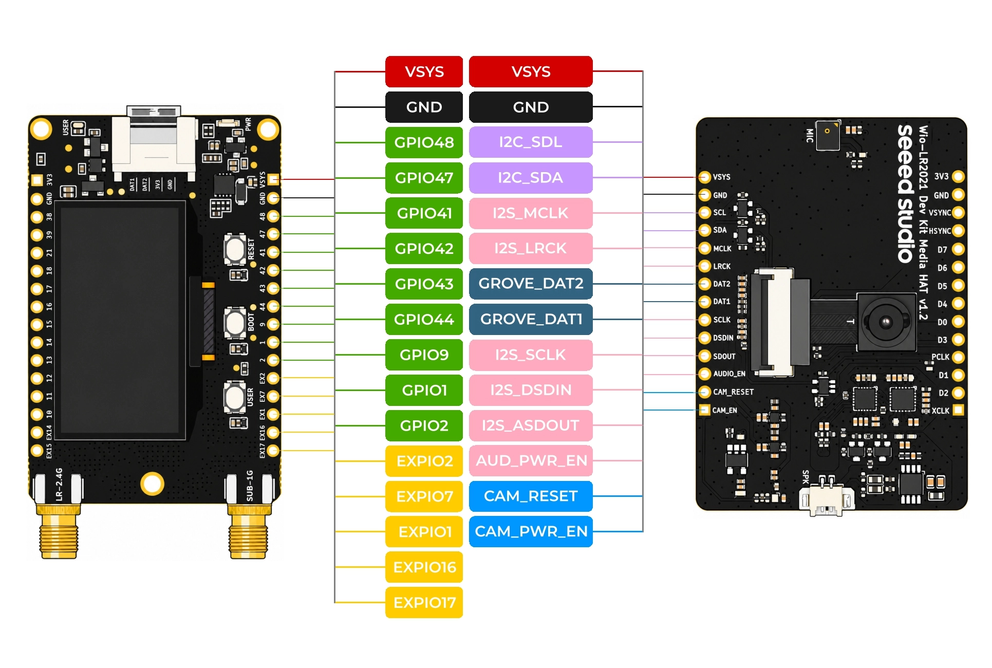
| Index | Function | ESP32-S3 pin | Description |
|---|---|---|---|
| 1 | VSYS | — | System rail, 5 V from USB or solar, 3.0 ~ 4.2 V on battery |
| 2 | GND | — | Ground |
| 3 | IIC0_SCL | GPIO48 | Shared I2C bus: OLED, PCA9535, HAT codec |
| 4 | IIC0_SDA | GPIO47 | Shared I2C bus: OLED, PCA9535, HAT codec |
| 5 | CODEC_I2S0_MCLK | GPIO41 | Audio clock for the ES8311 |
| 6 | CODEC_I2S0_LRCK | GPIO42 | Left and right channel select |
| 7 | GROVE_DAT_2 | GPIO43 | Grove data bit 2, UART0_TXD |
| 8 | GROVE_DAT_1 | GPIO44 | Grove data bit 1, UART0_RXD |
| 9 | CODEC_I2S0_SCLK | GPIO9 | Audio bit clock |
| 10 | CODEC_I2S0_DSDIN | GPIO1 | Playback data into the codec |
| 11 | CODEC_I2S0_SDOUT | GPIO2 | Recorded data from the codec |
| 12 | EXP_PWR_AUDIO_EN | PCA9535 P02 | Enables the audio rail on the HAT |
| 13 | EXP_CAM_RESET | PCA9535 P07 | Camera reset pin |
| 14 | EXP_PWR_CAM_EN | PCA9535 P01 | Enables the camera rail on the HAT |
| 15 | EXP_GPIO_P16 | PCA9535 P16 | Spare I/O through the expander |
| 16 | EXP_GPIO_P17 | PCA9535 P17 | Spare I/O through the expander |
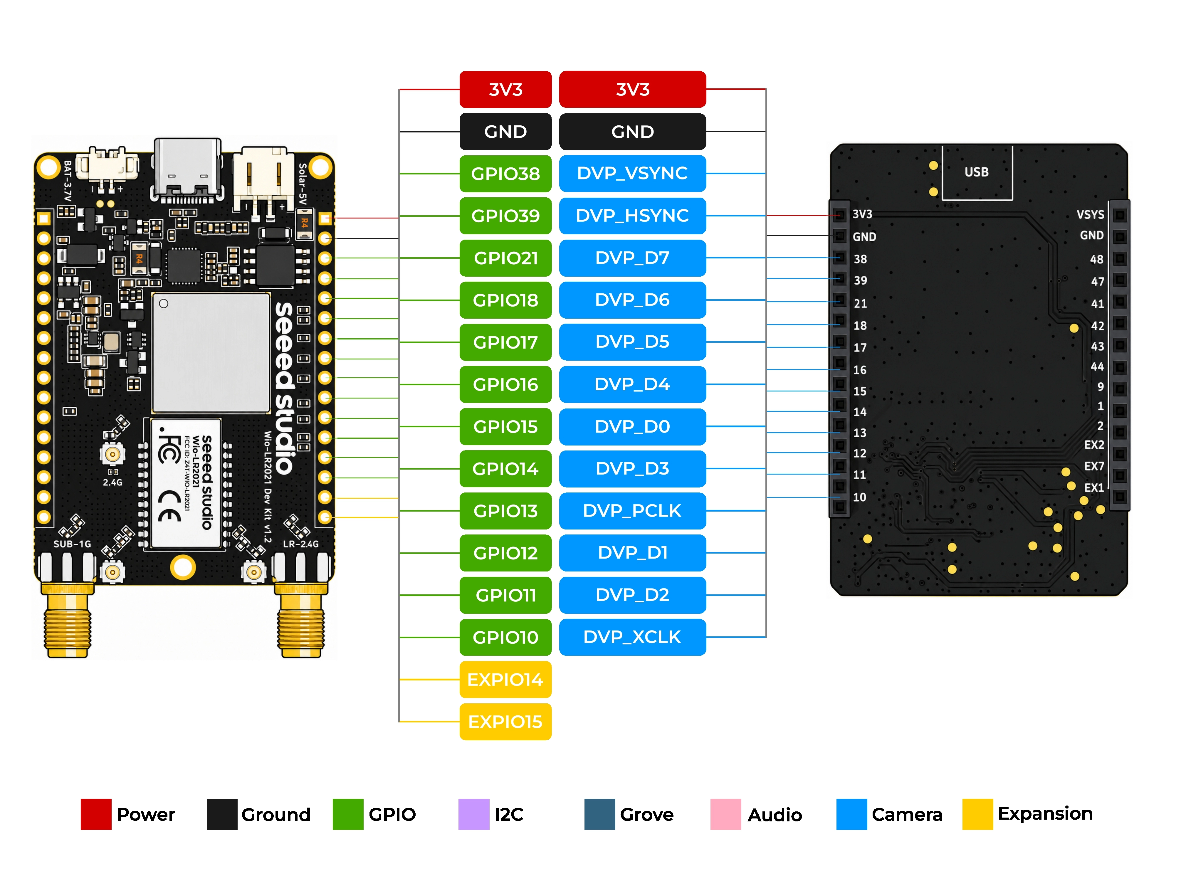
| Index | Function | ESP32-S3 pin | Description |
|---|---|---|---|
| 1 | VCC_3V3 | — | 3.3 V system rail |
| 2 | GND | — | Ground |
| 3 | DVP_VSYNC | GPIO38 | Camera vertical sync, VSYNC on the HAT |
| 4 | DVP_HSYNC | GPIO39 | Camera horizontal sync, HSYNC on the HAT |
| 5 | DVP_D7 | GPIO21 | Camera data bit 7 |
| 6 | DVP_D6 | GPIO18 | Camera data bit 6 |
| 7 | DVP_D5 | GPIO17 | Camera data bit 5 |
| 8 | DVP_D4 | GPIO16 | Camera data bit 4 |
| 9 | DVP_D0 | GPIO15 | Camera data bit 0 |
| 10 | DVP_D3 | GPIO14 | Camera data bit 3 |
| 11 | DVP_PCLK | GPIO13 | Camera pixel clock |
| 12 | DVP_D1 | GPIO12 | Camera data bit 1 |
| 13 | DVP_D2 | GPIO11 | Camera data bit 2 |
| 14 | DVP_XCLK | GPIO10 | Camera master clock, generated by the ESP32-S3 |
| 15 | EXP_GPIO_P14 | PCA9535 P14 | Spare I/O through the expander |
| 16 | EXP_GPIO_P15 | PCA9535 P15 | Spare I/O through the expander |
I/O Expander
The PCA9535 answers at I2C address 0x21, and its interrupt line runs to GPIO3. All 16 pins come up as inputs at power-on, so every rail and reset below stays inactive until firmware drives it.
| Port | Function | Notes |
|---|---|---|
| P00 | — | Not connected |
| P01 | EXP_PWR_CAM_EN | Camera rail enable |
| P02 | EXP_PWR_AUDIO_EN | Audio rail enable |
| P03 | EXP_PWR_OLED_EN | OLED rail enable |
| P04 | EXP_PWR_GROVE_EN | Grove rail enable |
| P05 | EXP_OLED_RST | OLED reset |
| P06 | EXP_User_LED | User LED (active LOW) |
| P07 | EXP_CAM_RESET | Camera reset |
| P10 | EXP_BAT_ADC_CTR | Gates the battery divider into GPIO8 |
| P11 | EXP_Sig_CHG_Done | Charge-complete flag from the CN3165 |
| P12 | EXP_Sig_CHGING | Charge-in-progress flag from the CN3165 |
| P13 | EXP_LoRa_RST | Wio-LR2021 reset |
| P14 | EXP_GPIO_P14 | PCA9535 P14 |
| P15 | EXP_GPIO_P15 | PCA9535 P15 |
| P16 | EXP_GPIO_P16 | PCA9535 P16 |
| P17 | EXP_GPIO_P17 | PCA9535 P17 |
Power Supply
| Rail | Range | Notes |
|---|---|---|
| VSYS | 3.0 ~ 5.5 V | Follows USB or solar when present, otherwise the battery |
| VCC_3V3 | 3.3 V | Buck output, up to the regulator current limit |
| VCC_Grove | 3.3 V | Switched by P04, protected by a 350 mA fuse |
| Solar+ | 5.0 V nominal | Reverse-blocked and over-voltage protected |
| BAT+ | 3.0 ~ 4.2 V | Li-ion cell, charged by the CN3165 |
VSYS is not a fixed 3.3 V rail. With USB or solar connected it sits near 5.0 V and will damage a 3.3 V-only peripheral.
Strapping Pins
The ESP32-S3 samples four pins at reset: GPIO0, GPIO3, GPIO45 and GPIO46. Two of them are routed out on the main board.
| Pin | Reaches | Description |
|---|---|---|
| GPIO0 | BOOT button | Held LOW with USER button, the chip enters the serial download mode instead of booting the firmware |
| GPIO46 | USER button | Held LOW with BOOT button, the chip enters the serial download mode instead of booting the firmware |
| GPIO3 | Not exposed | used as the INTERRUPT pin of PCA9535 |
| GPIO45 | Not exposed | used as the IRQ pin of Wio-LR2021 |
Getting Started
Hardware Preparation
Step 1 — Attach the antennas
Screw the Sub-GHz antenna onto the connector marked SUB-1G and the 2.4 GHz antenna onto the connector marked LR-2.4G. Tighten by hand only. If you use U.FL antennas instead, resolder the 0 Ω links to the corresponding pads and leave the SMA connectors empty.
Never transmit without an antenna. The LR2021 has no protection against an open port, and a continuous wave or a long transmit run into an open load can destroy the power amplifier.
Step 2 — Fit the Media HAT (optional)
Line up the two 14-pin sockets on the HAT with the two 16-pin headers on the main board, and press down evenly on both ends. The HAT draws its power from the main board, so no extra cable is needed. Remove it the same way, lifting both ends together.
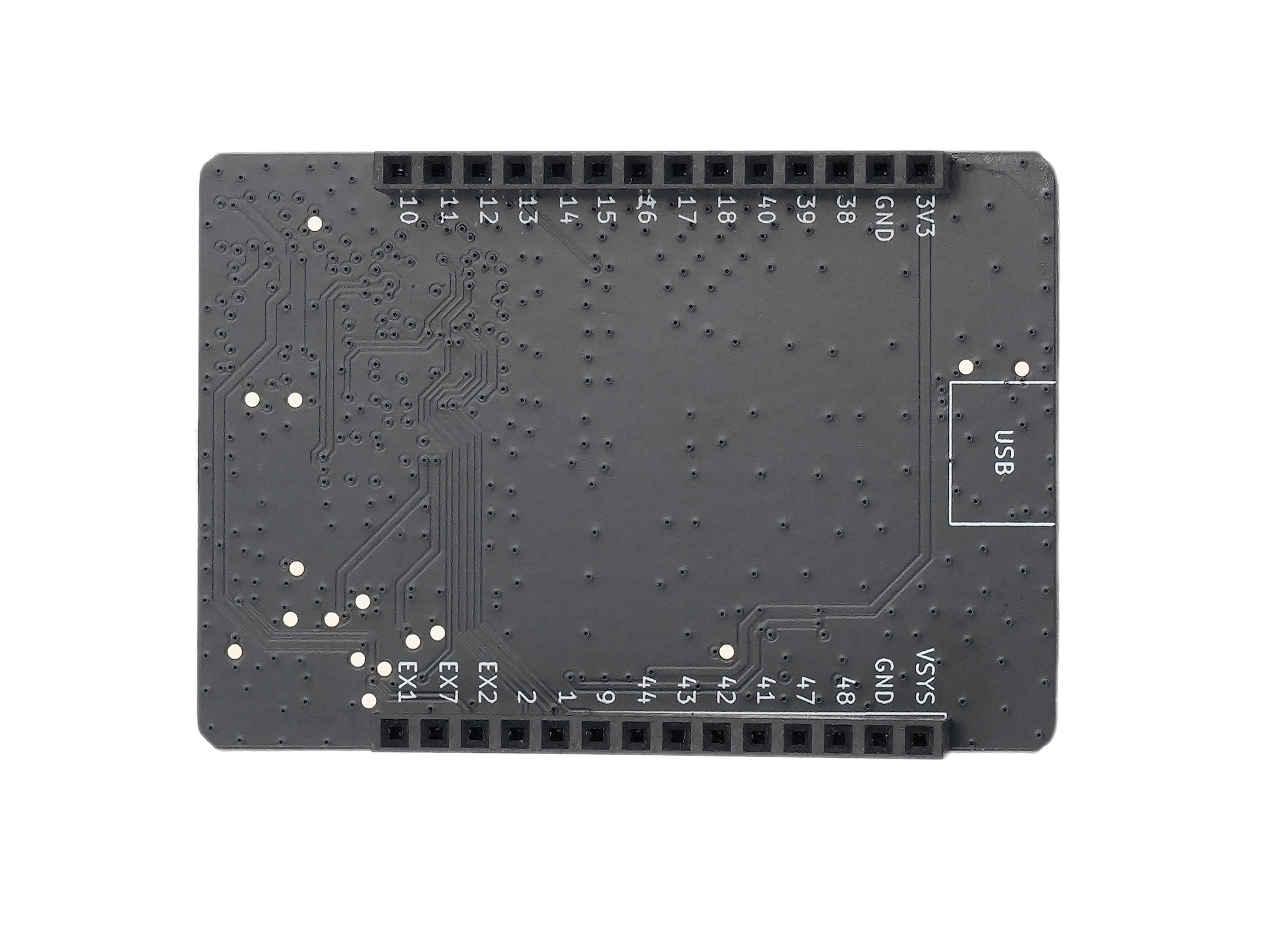
The back side of the expansion board is marked with the positions of the corresponding USB Type‑C ports on the motherboard, which can be used to determine the correct installation orientation. Next, locate the corresponding pins according to the pin's silkscreen on the PCB.
The sockets sit on the Media HAT, and the silkscreen next to each one prints the ESP32-S3 pin number, so you can check the orientation without a diagram.
Step 3 — Choose a power source
Any one of the three inputs will bring the board up: USB-C at 5 V, a 5 V solar panel on the Solar-5V JST connector, or a 3.7 V Li-ion cell on the BAT-3.7V connector. USB-C is the right choice for the first boot, because it also carries the serial console.
Resources
Tech Support & Product Discussion
Thank you for choosing our products! We are here to provide you with different support to ensure that your experience with our products is as smooth as possible. We offer several communication channels to cater to different preferences and needs.