Getting Started with Seeed Studio XIAO ESP32-C5
Introduction
| Seeed Studio XIAO ESP32-C5 |
|---|
 |
Specification
| Item | Seeed Studio XIAO ESP32-C5 | Seeed Studio XIAO ESP32-S3 | Seeed Studio XIAO ESP32-C3 | Seeed Studio XIAO ESP32-C6 |
|---|---|---|---|---|
| Processor | ESP32-C5 RISC-V 32-bit @240 MHz | ESP32R8N8 32-bit Xtensa LX7 dual-core @240 MHz | ESP32-C3 32-bit RISC-V @160 MHz | ESP32-C6 32-bit RISC-V @160 MHz |
| Wireless Connectivity | 2.4 GHz & 5 GHz dual-band Wi-Fi 6 and Bluetooth 5 (LE) | 2.4 GHz Wi-Fi and Bluetooth 5 (LE) | 2.4 GHz Wi-Fi and Bluetooth 5 (LE) | 2.4 GHz Wi-Fi 6, Bluetooth 5 (LE) |
| Memory | 8 MB PSRAM & 8 MB Flash | 8 MB PSRAM & 8 MB Flash | 400 KB SRAM, 4 MB Flash | 512KB SRAM , 4MB Flash |
| Interfaces | I2C / UART / SPI | I2C / UART / SPI | I2C / UART / SPI | I2C / UART / SPI |
| PWM/Analog Pins | 11 / 5 | 11 / 9 | 11 / 4 | 11 / 7 |
| Onboard Buttons | Reset / Boot Button | Reset / Boot Button | Reset / Boot Button | Reset button / Boot button |
| Onboard LEDs | Charge / USER LED | Charge / USER LED | Charge LED | Charge / USER LED |
| Battery Charge Chip | SGM40567 | SGM40567 | ETA4054S2F | SGM40567 |
Features
- Powerful CPU: ESP32-C5, 32bit RISC-V singlecore processor that operates at up to 240 MHz
- Complete WiFi subsystem: Dual-band Wi-Fi 6 subsystem (2.4 GHz and 5 GHz) compliant with IEEE 802.11 a/b/g/n/ac/ax, supporting Station, SoftAP, concurrent SoftAP+Station operation, and promiscuous (monitor) mode.
- Bluetooth LE subsystem: Supports features of Bluetooth 5 and Bluetooth mesh
- Better RF performance: External RF antenna included.
- Battery charging chip: Supports lithium battery charge and discharge management.
- Rich on-chip resources: 384 KB on-chip SRAM, 320 KB of ROM
- Ultra small size: As small as a thumb(21x17.8mm) XIAO series classic form-factor for wearable devices and small projects
- Reliable security features: Cryptographic hardware accelerators supporting AES-128/256, SHA family hashing, HMAC, a dedicated digital signature peripheral, and Secure Boot (V2).
- Rich interfaces: 1×I2C, 1×SPI, 2×UART, up to 11×GPIO (PWM-capable), 5×ADC channels, and a JTAG(pads on the reverse side) bonding-pad interface.
- Single-sided components, surface mounting design
Hardware overview
| XIAO ESP32-C5 indication diagram |
|---|
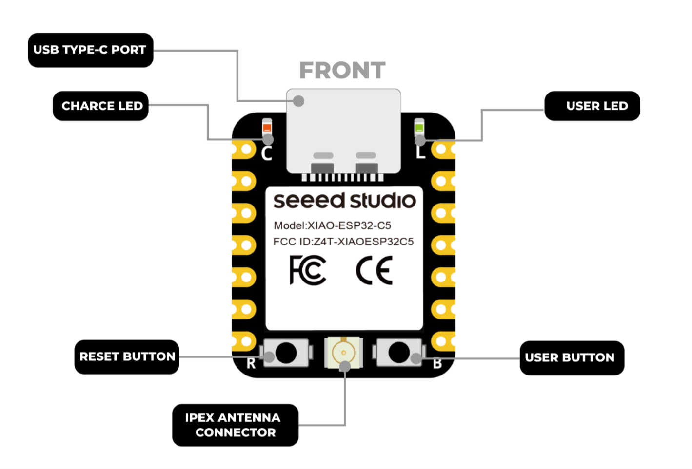 |
| XIAO ESP32-C5 Pin List |
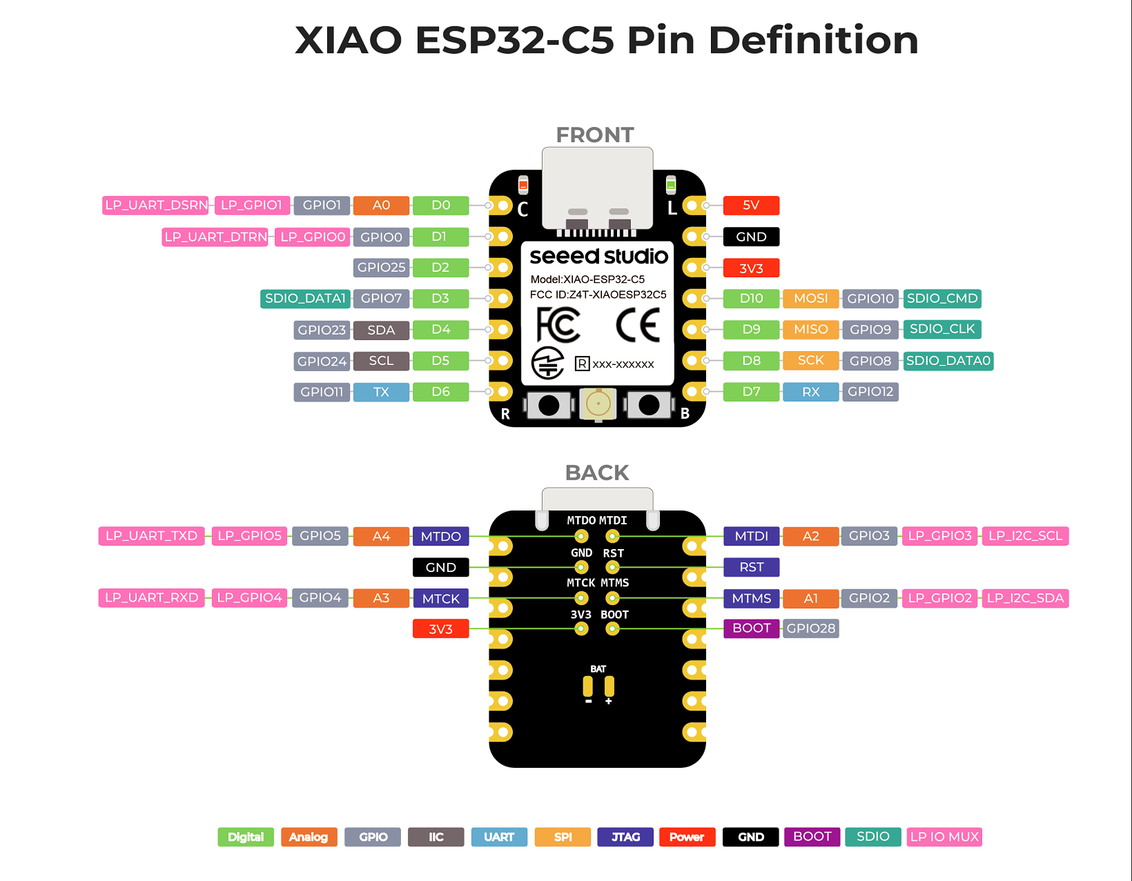 |
Pin Map
| XIAO Pin | Function | Chip Pin | Alternate Functions | Description |
|---|---|---|---|---|
| 5V | VBUS | Power Input/Output | ||
| GND | ||||
| 3V3 | 3V3_OUT | Power Output | ||
| D0 | Analog | GPIO1 | LP_UART_DSRN, LP_GPIO1 | GPIO, ADC |
| D1 | GPIO0 | LP_UART_DTRN, LP_GPIO0 | GPIO | |
| D2 | GPIO25 | GPIO | ||
| D3 | GPIO7 | SDIO_DATA1 | GPIO | |
| D4 | SDA | GPIO23 | GPIO, I2C Data | |
| D5 | SCL | GPIO24 | GPIO, I2C Clock | |
| D6 | TX | GPIO11 | GPIO, UART Transmit | |
| D7 | RX | GPIO12 | GPIO, UART Receive | |
| D8 | SCK | GPIO8 | TOUCH7 | GPIO, SPI Clock |
| D9 | MISO | GPIO9 | TOUCH8 | GPIO, SPI Data |
| D10 | MOSI | GPIO10 | TOUCH9 | GPIO, SPI Data |
| MTDO | GPIO5 | LP_UART_TXD, LP_GPIO5 | JTAG | |
| MTDI | GPIO3 | LP_I2C_SCL, LP_GPIO3 | JTAG, ADC | |
| MTCK | GPIO4 | LP_UART_RXD, LP_GPIO4 | JTAG, ADC | |
| MTMS | GPIO2 | LP_I2C_SDA, LP_GPIO2 | JTAG, ADC | |
| ADC_BAT | GPIO6 | Read the BAT voltage value | ||
| ADC_CRL | GPIO26 | Controls (enables/disables) the measurement circuit to save power. | ||
| Reset | CHIP_EN | EN | ||
| Boot | GPIO28 | Enter Boot Mode | ||
| U.FL-R-SMT1 | LNA_IN | UFL antenna | ||
| CHARGE_LED | VCC_3V3 | CHG-LED_Red | ||
| USER_LED | GPIO27 | User Light_Yellow |
Getting Started
To enable you to get started with the XIAO ESP32-C5 faster, please read the hardware and software preparation below to prepare the XIAO.
Hardware
You need to prepare the following:
- 1 x Seeed Studio XIAO ESP32-C5
- 1 x Computer
- 1 x USB Type-C cable
| Seeed Studio XIAO ESP32-C5 |
|---|
 |
Some USB cables can only supply power and cannot transfer data. If you don't have a USB cable or don't know if your USB cable can transmit data, you can check Seeed USB Type-C support USB 3.1.
Software
The recommended programming tool for the XIAO ESP32-C5 is the Arduino IDE, so you need to complete the Arduino installation as part of the software preparation.
If this is your first time using Arduino, we highly recommend you to refer to Getting Started with Arduino.
-
Step 1. Download and Install the stable version of Arduino IDE according to your operating system.
-
Step 2. Launch the Arduino application.
-
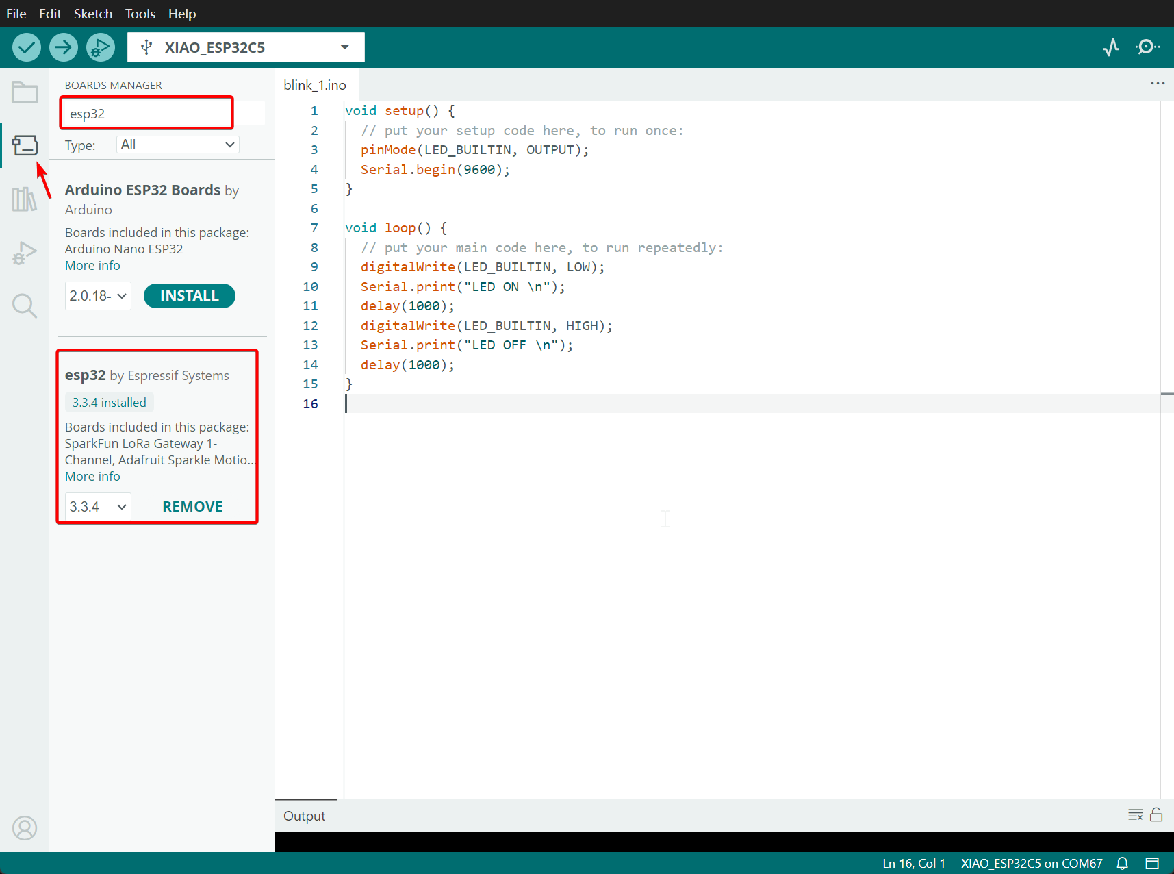
Step 3. Open BOARDS MANAGER -> Search esp32 -> Install version 3.3.5 or a higher version
Upload Progaram
Let's take a lighting program as an example below
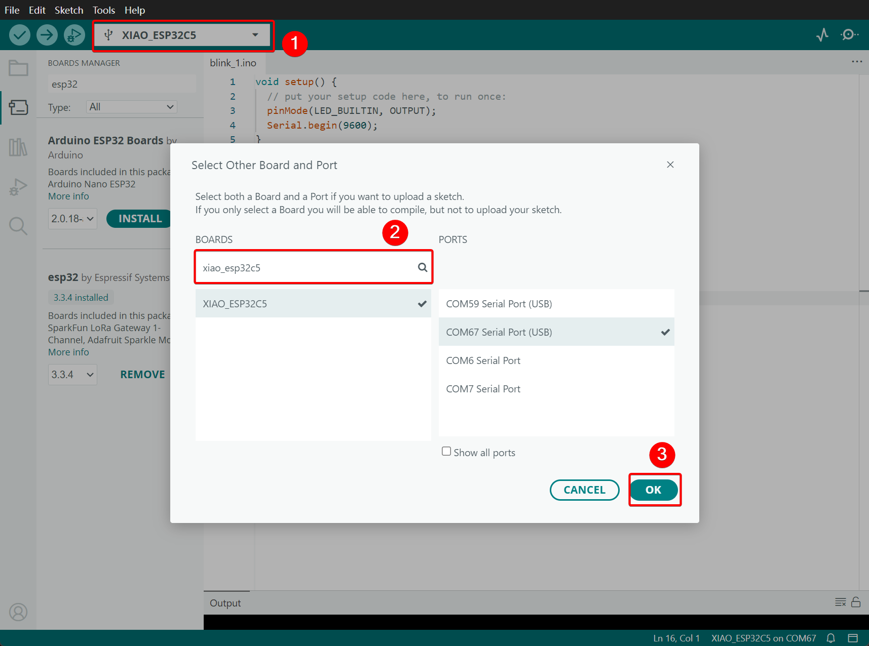
Step 1. Select XIAO_ESP32C5 and PORT. If you don't know the PORT, you can reinsert and remove the XIAO_ESP3-2C5 to check.
Step 2. Paste Code in your Skecth
LED_BUILTIN corresponds to the L LED on the development board.
void setup() {
  // put your setup code here, to run once:
  pinMode(LED_BUILTIN, OUTPUT);
  Serial.begin(9600);
}

void loop() {
  // put your main code here, to run repeatedly:
  digitalWrite(LED_BUILTIN, LOW);
  Serial.print("LED ON \n");
  delay(1000);
  digitalWrite(LED_BUILTIN, HIGH);
  Serial.print("LED OFF \n");
  delay(1000);
}
Step 3. Click and Upload

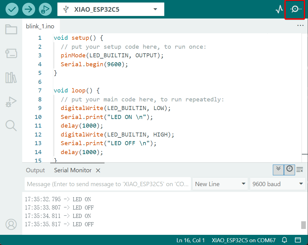
Effect demonstration:
After you upload the program, you will see the L indicator light flashing at intervals of 1 second, and at the same time, the serial monitor will print LED ON and LED OFF.
Deep sleep mode
The XIAO ESP32-C5 features deep sleep and wake-up functions. This example utilizes a high-level trigger on pin D0 to wake the device from deep sleep.
It is important to note that this is a configurable option, as the hardware supports both high-level and low-level triggers to accommodate different circuit designs.
#define WAKEUP_PIN D0 // LP_GPIO1

RTC_DATA_ATTR int bootCount = 0;

void print_wakeup_reason(){
  esp_sleep_wakeup_cause_t wakeup_reason = esp_sleep_get_wakeup_cause();

  switch(wakeup_reason)
  {
    case ESP_SLEEP_WAKEUP_EXT0 : Serial.println("Wakeup caused by external signal using RTC_IO"); break;
    case ESP_SLEEP_WAKEUP_EXT1 : Serial.println("Wakeup caused by external signal using RTC_CNTL"); break;
    case ESP_SLEEP_WAKEUP_TIMER : Serial.println("Wakeup caused by timer"); break;
    case ESP_SLEEP_WAKEUP_TOUCHPAD : Serial.println("Wakeup caused by touchpad"); break;
    case ESP_SLEEP_WAKEUP_ULP : Serial.println("Wakeup caused by ULP program"); break;
    case ESP_SLEEP_WAKEUP_GPIO : Serial.println("Wakeup caused by GPIO"); break;
    default : Serial.printf("Wakeup was not caused by deep sleep: %d\n",wakeup_reason); break;
  }
}

void setup(){
  Serial.begin(115200);
  delay(1000);

  ++bootCount;
  Serial.println("Boot number: " + String(bootCount));
  print_wakeup_reason();

  pinMode(WAKEUP_PIN, INPUT_PULLUP);
  pinMode(LED_BUILTIN, OUTPUT);

  uint64_t mask = 1ULL << WAKEUP_PIN;
  esp_deep_sleep_enable_gpio_wakeup(mask, ESP_GPIO_WAKEUP_GPIO_HIGH);

  digitalWrite(LED_BUILTIN, LOW);
  delay(100);
  digitalWrite(LED_BUILTIN, HIGH);

  delay(2000);  //Delay time depends on the serial port / Give the PC time to stabilize
  Serial.println("Going to sleep now");
  esp_deep_sleep_start();
}

void loop(){}
If you are quick enough to turn on the serial monitor before the XIAO goes into deep sleep, then you can see the message output as shown below. This means that the XIAO is now asleep. Then you can also view and activate it by pressing the button.You can also observe the on-off state of the L LED to check if the device has been awakened. Once it is awakened, it will exhibit a flashing effect.
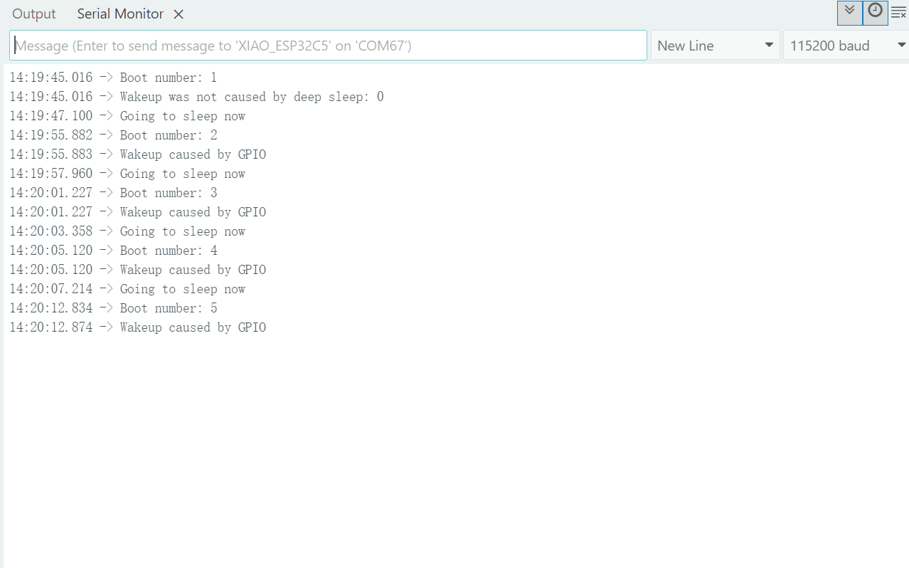
After entering deep sleep mode, the XIAO's port will disappear and you'll need to wake it up to see its port number again!
The XIAO ESP32-C5 supports GPIO wake-up and timer wake-up. To prevent the loss of hardware debugging capabilities and increased difficulty in firmware flashing during low-power development, it is strongly recommended that the JTAG (MTMS, MTDI, MTCK, MTDO) pins be reserved for dedicated use and not employed as wake-up sources for deep sleep mode.
Battery Usage
The XIAO ESP32-C5 is capable of using a 3.7V lithium battery as the power supply input. You can refer to the following diagram for the wiring method.
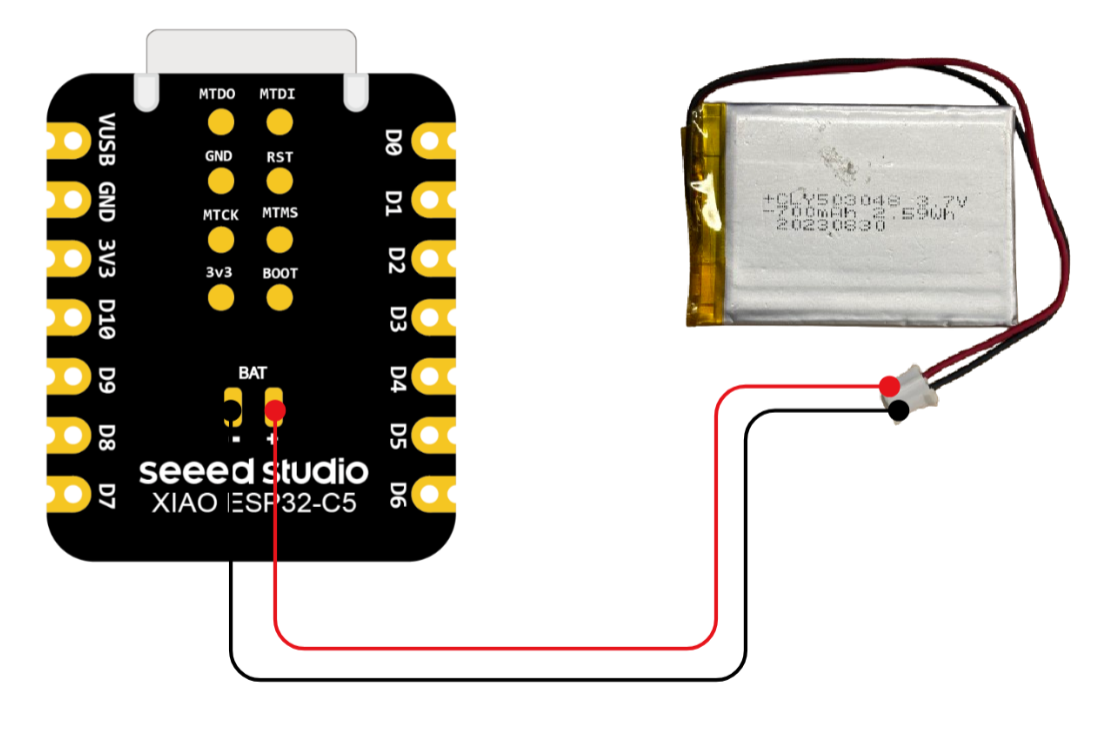
Please be careful not to short-circuit the positive and negative terminals and burn the battery and equipment when soldering.
Instructions on the use of batteries:
- Please use qualified batteries that meet the specifications.
- XIAO can be connected to your computer device via data cable while using the battery, rest assured that XIAO has a built-in circuit protection chip, which is safe.
- When XIAO ESP32-C5 is powered by a battery, the C LED will light up. You can use this as a basis for determining whether charging management has been carried out.
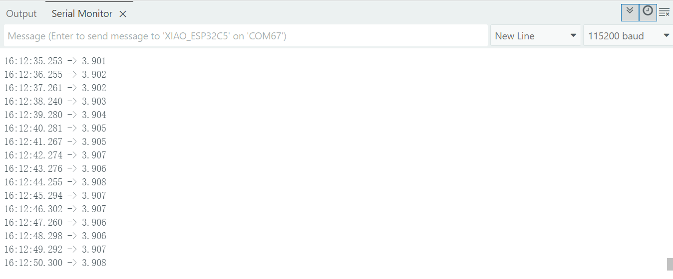
Check the battery voltage
The XIAO ESP32-C5 is equipped with the SGM40567 battery charging chip and the TPS22916CYFPR battery voltage acquisition chip. You can enable the BAT_VOLT_PIN_EN to activate the battery voltage acquisition function and read the battery voltage through the BAT_VOLT_PIN.
On the XIAO ESP32C5, the pin corresponding to BAT_VOLT_PIN is GPIO6, and the pin corresponding to BAT_VOLT_PIN_EN is GPIO26.
#include <Arduino.h>

void setup() {
  Serial.begin(115200);
  pinMode(BAT_VOLT_PIN, INPUT);         // Configure A0 as ADC input
  pinMode(BAT_VOLT_PIN_EN , OUTPUT);
  digitalWrite(BAT_VOLT_PIN_EN , HIGH);
}

void loop() {
  uint32_t Vbatt = 0;
  for(int i = 0; i < 16; i++) {
    Vbatt += analogReadMilliVolts(BAT_VOLT_PIN ); // Read and accumulate ADC voltage
  }
  float Vbattf = 2 * Vbatt / 16 / 1000.0;     // Adjust for 1:2 divider and convert to volts
  Serial.println(Vbattf, 3);                  // Output voltage to 3 decimal places
  delay(1000);                                // Wait for 1 second
}
-
analogReadMilliVolts(BAT_Voltage_Read)- This function is used to read the current analog voltage from the
BAT_VOLT_PINpin and return a calibrated voltage value in millivolts (mV). - Unlike the conventional
analogRead(), which only provides a raw ADC value,analogReadMilliVolts()automatically applies the factory calibration parameters embedded in the chip. This results in higher accuracy, improved linearity in voltage measurement, and eliminates the need for manual ADC-to-voltage conversion. - During the voltage sampling process, a 16-times repeated sampling is performed through a
forloop, and the results are accumulated. The purpose of multiple sampling is to suppress transient noise and discrete errors, thereby improving measurement stability. Finally, the accumulated value is divided by the number of samples (16) to obtain a smoother and more reliable averaged voltage value.
- This function is used to read the current analog voltage from the
According to the datasheet, the effective measurement range of the ESP32-C5 covers 0~3300 mV. Therefore, the built-in battery voltage acquisition circuit of the XIAO ESP32-C5 is designed with two 100K resistors for voltage division, enabling accurate reading of values.
Resource
Hardware Design
- 📄[Datasheet] Espressif ESP32-C5 Datasheet
- 📄[Schematic] XIAO ESP32-C5 Schematic
- 🗃️[PCB Design Files] XIAO ESP32-C5 KiCad Project
- 🗃️[PCB Design Libraries]
- XIAO Series KiCad SCH Symbols
- 📄[Pinout Diagram] XIAO ESP32-C5 Pinout Sheet
Mechanical Design
- 📄[3D Model] XIAO ESP32-C5 3D Model
Tech Support & Product Discussion
Thank you for choosing our products! We are here to provide you with different support to ensure that your experience with our products is as smooth as possible. We offer several communication channels to cater to different preferences and needs.