Pin Multiplexing with Seeed Studio XIAO ESP32-C5
| Seeed Studio XIAO ESP32-C5 |
|---|
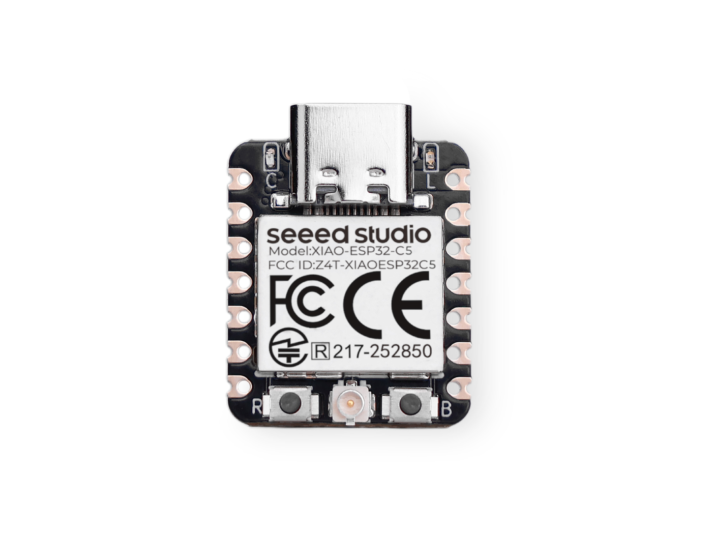 |
The Seeed Studio XIAO ESP32-C5 is a powerful and versatile development board that features a variety of peripheral interfaces and GPIO pins. These pins can be used for various purposes, such as communicating with other devices, reading analog sensors, controlling LEDs, and more. In this tutorial, we will guide you on how to use the multiplexed pins of the XIAO ESP32-C5.
In summary, the XIAO ESP32-C5 features 1×I2C, 1×SPI, 2×UART, up to 11×GPIO (PWM-capable), 5×ADC channels, and a JTAG(pads on the reverse side) bonding-pad interface.
Getting Started
Next, I will provide example tutorials and code respectively based on the two platforms: PlatformIO and Arduino IDE, and you can choose the development platform according to your specific circumstances.
If you have not used Arduino IDE before, please refer to Getting Started with Seeed Studio XIAO ESP32-C5.
If you have not used PlatfromIO before, please refer to Platform IO with Seeed Studio XIAO ESP32-C5。
Pinout Overview
Before we begin, let's review all the pins that the XIAO ESP32-C5 has and its functions with the following schematic.
| XIAO ESP32-C5 indication diagram |
|---|
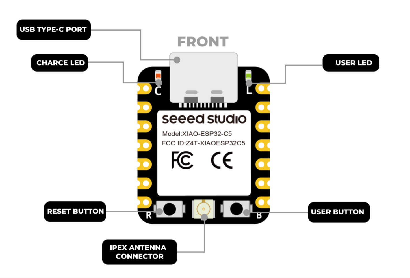 |
| XIAO ESP32-C5 Pin List |
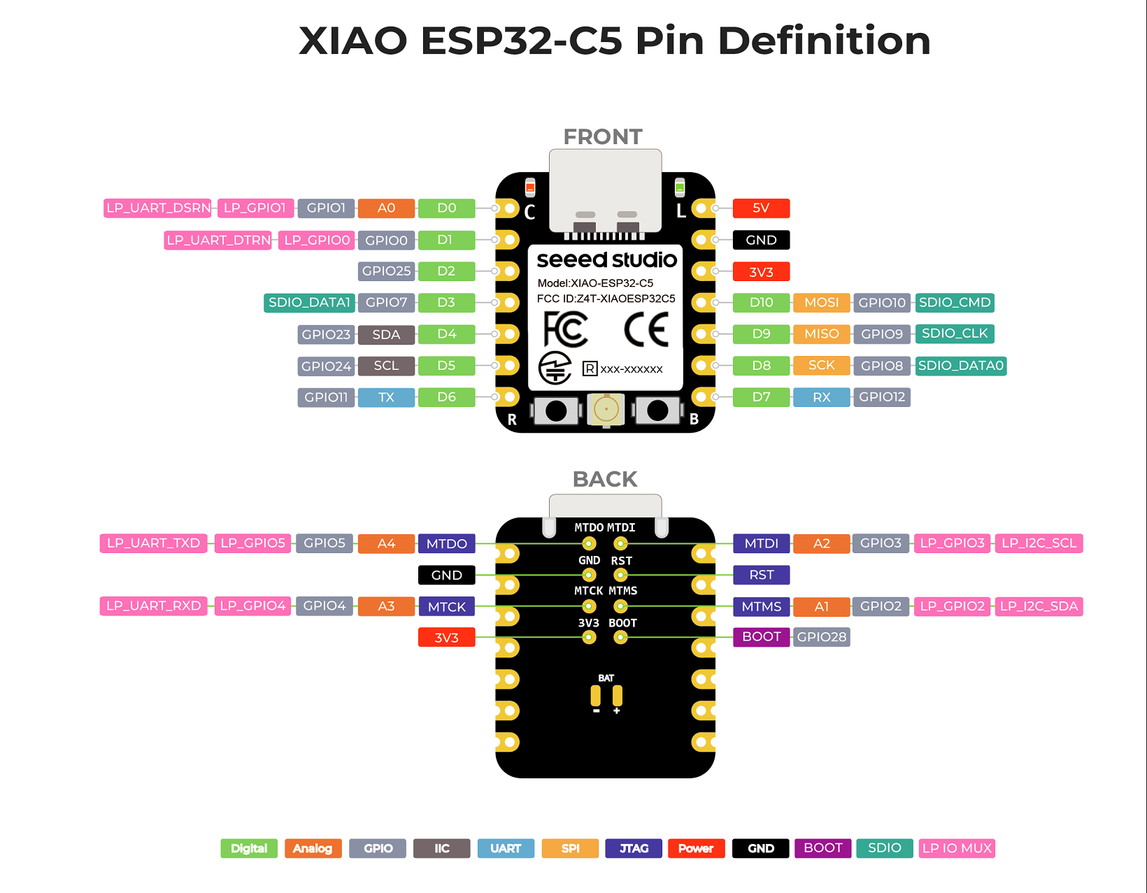 |
Digital
All 11 IO pins (D0–D10) of the XIAO ESP32-C5 support digital functions. Below is a practical example demonstrating how to use digital functions to control the on/off state of a light, and you can multiplex these pins according to your specific requirements.
Hardware Preperation
| Seeed Studio XIAO ESP32-C5 | Seeed Studio Grove Base for XIAO | Grove - Variable Color LED | Grove - Button |
|---|---|---|---|
|  |  |  |
Software
The following code examples are based on Arduino IDE and PlatformIO respectively, and they achieve the same control effect. You can select and reuse the appropriate code according to your actual development situation.
- Arduino IDE
- PlatformIO
- Reference Code
const int buttonPin = D1;   // Button pin
const int ledPin    = D0;   // LED pin

bool ledState = false;      // LED current state (OFF/ON)

// Debounce
const unsigned long DEBOUNCE_MS = 30;
bool lastReading = HIGH;          // because INPUT_PULLUP idle is HIGH
bool stableState = HIGH;
unsigned long lastChangeTime = 0;

void setup() {
  pinMode(ledPin, OUTPUT);

  pinMode(buttonPin, INPUT_PULLUP);

}

void loop() {
  bool reading = digitalRead(buttonPin);

  // Detect a level change and start timing (for debouncing)
  if (reading != lastReading) {
    lastChangeTime = millis();
    lastReading = reading;
  }

  if (millis() - lastChangeTime >= DEBOUNCE_MS) {
    if (stableState != reading) {
      stableState = reading;


      if (stableState == LOW) {
        ledState = !ledState;                 // toggle
        digitalWrite(ledPin, ledState ? HIGH : LOW);
      }
    }
  }
}
- Ensure the content of
platform.iniis as follows.
[env:seeed-xiao-esp32-c5]
platform = Seeed Studio
board = seeed-xiao-esp32-c5
framework = arduino
- Reference Code
#include <Arduino.h>

const int buttonPin = D1;   // Button pin
const int ledPin    = D0;   // LED pin

bool ledState = false;      // LED current state (OFF/ON)

// Debounce
const unsigned long DEBOUNCE_MS = 30;
bool lastReading = HIGH;          // because INPUT_PULLUP idle is HIGH
bool stableState = HIGH;
unsigned long lastChangeTime = 0;

void setup() {
  pinMode(ledPin, OUTPUT);

  pinMode(buttonPin, INPUT_PULLUP);

}

void loop() {
  bool reading = digitalRead(buttonPin);

  // Detect a level change and start timing (for debouncing)
  if (reading != lastReading) {
    lastChangeTime = millis();
    lastReading = reading;
  }

  if (millis() - lastChangeTime >= DEBOUNCE_MS) {
    if (stableState != reading) {
      stableState = reading;


      if (stableState == LOW) {
        ledState = !ledState;                 // toggle
        digitalWrite(ledPin, ledState ? HIGH : LOW);
      }
    }
  }
}
Result
- After uploading the code, press the button—each press toggles the LED on and off, simulating the real-life effect of controlling a light.
If the above effect is not achieved after you press the button, you may need to press the onboard RESET button first to wake up the board.
PWM
All pins D0–D11 of the XIAO ESP32-C5 support PWM functionality. PWM can be used to drive devices such as servos, motors, and LED lights. Below is an example of PWM-controlled breathing lights to demonstrate the functionality of PWM.
Hardware Preperation
| Seeed Studio XIAO ESP32-C5 | Seeed Studio Grove Base for XIAO | Grove - Variable Color LED |
|---|---|---|
| | |
Software
The following code examples are based on Arduino IDE and PlatformIO respectively, and they achieve the same control effect. You can select and reuse the appropriate code according to your actual development situation.
- Arduino IDE
- PlatformIO
- Reference Code
int ledPin = D1;    // LED connected to digital pin 10

void setup() {
  // declaring LED pin as output
  pinMode(ledPin, OUTPUT);
}

void loop() {
  // fade in from min to max in increments of 5 points:
  for (int fadeValue = 0 ; fadeValue <= 255; fadeValue += 5) {
    // sets the value (range from 0 to 255):
    analogWrite(ledPin, fadeValue);
    // wait for 30 milliseconds to see the dimming effect
    delay(30);
  }

  // fade out from max to min in increments of 5 points:
  for (int fadeValue = 255 ; fadeValue >= 0; fadeValue -= 5) {
    // sets the value (range from 0 to 255):
    analogWrite(ledPin, fadeValue);
    // wait for 30 milliseconds to see the dimming effect
    delay(30);
  }
}
- Ensure the content of
platform.iniis as follows.
[env:seeed-xiao-esp32-c5]
platform = Seeed Studio
board = seeed-xiao-esp32-c5
framework = arduino
- Reference Code
#include <Arduino.h>

int ledPin = D0;    // LED connected to digital pin 10

void setup() {
  // declaring LED pin as output
  pinMode(ledPin, OUTPUT);
}

void loop() {
  // fade in from min to max in increments of 5 points:
  for (int fadeValue = 0 ; fadeValue <= 255; fadeValue += 5) {
    // sets the value (range from 0 to 255):
    analogWrite(ledPin, fadeValue);
    // wait for 30 milliseconds to see the dimming effect
    delay(30);
  }

  // fade out from max to min in increments of 5 points:
  for (int fadeValue = 255 ; fadeValue >= 0; fadeValue -= 5) {
    // sets the value (range from 0 to 255):
    analogWrite(ledPin, fadeValue);
    // wait for 30 milliseconds to see the dimming effect
    delay(30);
  }
}
Result
After uploading the code, the Grove - Variable Color LED will display a breathing light effect.
Analog
For the XIAO ESP32-C5, pins A0–A5 support analog reading functionality. ADC reading can be applied to scenarios such as measuring battery voltage and reading rotary encoders. Next, we will demonstrate the ADC reading function by taking the voltage measurement of the Grove-Rotary Angle Sensor as an example.
Hardware Preperation
| Seeed Studio XIAO ESP32-C5 | Seeed Studio Grove Base for XIAO | Grove - Rotary Angle Sensor |
|---|---|---|
| |  |
Software
The following code examples are based on Arduino IDE and PlatformIO respectively, and they achieve the same control effect. You can select and reuse the appropriate code according to your actual development situation.
- Arduino IDE
- PlatformIO
iconst int analogPin = A0;

void setup() {
  // Initialize serial communication at 115200 bits per second
  Serial.begin(115200);

  // Set the resolution to 12 bits (0-4095)
  analogReadResolution(12);
}

void loop() {
  // Read the analog value and millivolts for the analogPin
  int analogValue = analogRead(analogPin);
  int analogVolts = analogReadMilliVolts(analogPin);

  // Convert millivolts to volts
  float voltage = analogVolts / 1000.0;

  // Print the values to the Serial Monitor
  Serial.printf("ADC analog value = %d\n", analogValue);
  Serial.printf("ADC millivolts value = %d\n", analogVolts);
  Serial.printf("Voltage = %.3f V\n", voltage);

  delay(1000); // Delay for clear reading from serial
}
- Ensure the content of
platform.iniis as follows.
[env:seeed-xiao-esp32-c5]
platform = Seeed Studio
board = seeed-xiao-esp32-c5
framework = arduino
- Reference Code
#include <Arduino.h>

iconst int analogPin = A0;

void setup() {
  // Initialize serial communication at 115200 bits per second
  Serial.begin(115200);

  // Set the resolution to 12 bits (0-4095)
  analogReadResolution(12);
}

void loop() {
  // Read the analog value and millivolts for the analogPin
  int analogValue = analogRead(analogPin);
  int analogVolts = analogReadMilliVolts(analogPin);

  // Convert millivolts to volts
  float voltage = analogVolts / 1000.0;

  // Print the values to the Serial Monitor
  Serial.printf("ADC analog value = %d\n", analogValue);
  Serial.printf("ADC millivolts value = %d\n", analogVolts);
  Serial.printf("Voltage = %.3f V\n", voltage);

  delay(1000); // Delay for clear reading from serial
}
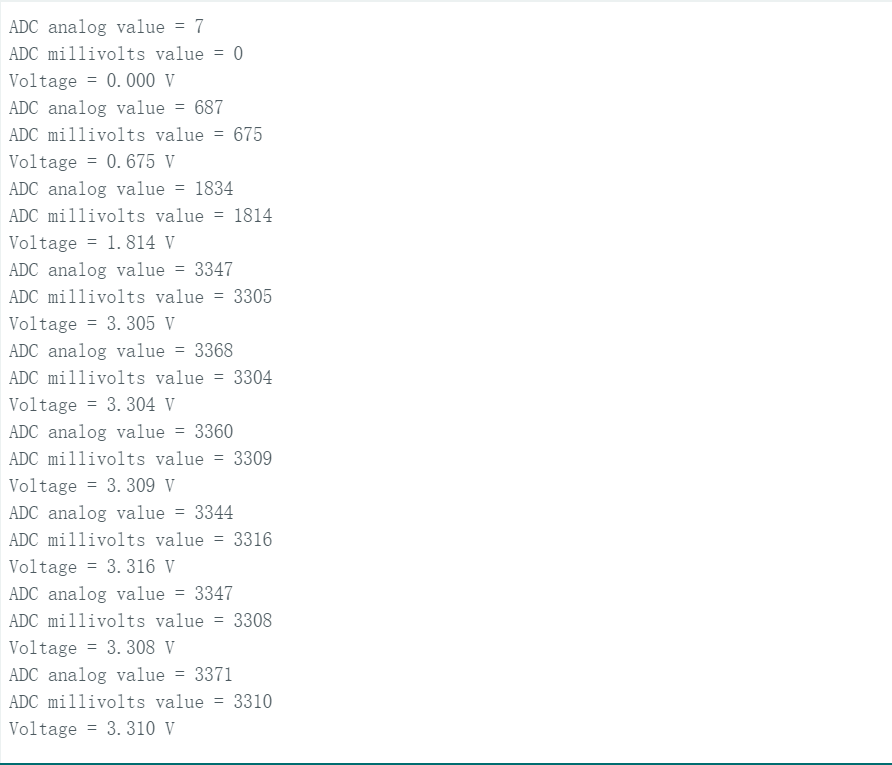
Result
Open the serial monitor, and it will print the raw ADC value (analogValue), millivolt value (analogVolts), and voltage value (voltage) read from the Grove-Rotary Angle Sensor. Obvious changes will occur as you rotate the Grove-Rotary Angle Sensor.
Serial Communication
The XIAO ESP32-C5 features two hardware serial communication interfaces: USB Serial and UART1 Serial, which you can utilize for serial communication. In addition, you can use other general-purpose pins to simulate serial communication interfaces.
USB / UART1 Serial
For USB Serial, connect the board directly to a computer via USB-C for monitoring — this is the interface used in the previous examples. For UART1 Serial, use the Seeed Studio XIAO Debug Mate for monitoring.
Hardware Preparation
| Seeed Studio XIAO ESP32-C5 | Seeed Studio XIAO Debug Mate |
|---|---|
|  |
Software
The following code examples are based on Arduino IDE and PlatformIO respectively, and they achieve the same control effect. You can select and reuse the appropriate code according to your actual development situation.
The corresponding pins for Serial1 are RX_PIN - D7 and TX_PIN - D6.
- Arduino IDE
- PlatformIO
- Reference Code
#define RX_PIN D7
#define TX_PIN D6
#define BAUD 115200

void setup() {
    Serial.begin(115200);
    Serial1.begin(BAUD,SERIAL_8N1,RX_PIN,TX_PIN);
}

void loop() {
    Serial.print("PC Serial \n");
    Serial1.print("Hello XIAO ESP32-C5\n");
  delay(1000);
}
- Ensure the content of platform.ini is as follows.
[env:seeed-xiao-esp32-c5]
platform = Seeed Studio
board = seeed-xiao-esp32-c5
framework = arduino
- Reference Code
#include <Arduino.h>

#define RX_PIN D7
#define TX_PIN D6
#define BAUD 115200

void setup() {
    Serial.begin(115200);
    Serial1.begin(BAUD,SERIAL_8N1,RX_PIN,TX_PIN);
}

void loop() {
    Serial.print("PC Serial \n");
    Serial1.print("Hello XIAO ESP32-C5\n");
  delay(1000);
}
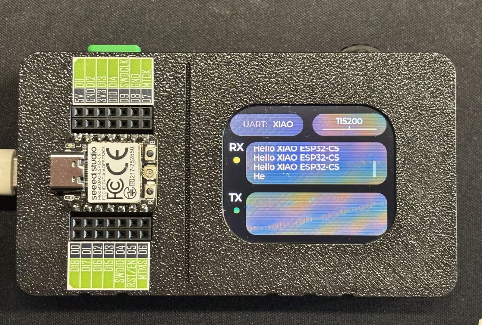
Result
After uploading the program, you can monitor it via the UART function of the Seeed Studio XIAO Debug Mate.
If you have not used the Seeed Studio XIAO Debug Mate before, you can visit Getting Started with XIAO Debug Mate.
Software Serial
This section will demonstrate the functionality of software serial communication by simulating serial communication pins using general-purpose pins.
Hardware Preparation
| Seeed Studio XIAO ESP32-C5 | CH340G USB to Serial (TTL) Module&Adapter |
|---|---|
|  |
Software
The following code examples are based on Arduino IDE and PlatformIO respectively, and they achieve the same control effect. You can select and reuse the appropriate code according to your actual development situation.
The corresponding software-simulated pins are RX_PIN - D2 and TX_PIN - D1.
- Arduino IDE
- PlatformIO
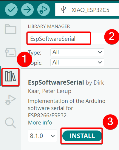
- Install the
EspSoftwareSerialdependency library.
- Reference Code
#include <SoftwareSerial.h>

#define MYPORT_TX D1
#define MYPORT_RX D2

EspSoftwareSerial::UART mySerial;

String receivedData = "";  // Used for storing the received data
unsigned long lastReceiveTime = 0;  // Record the last reception time
const unsigned long TIMEOUT = 100;  // 100ms timeout period

void setup() {
  Serial.begin(115200); //USB-C
  mySerial.begin(38400, SWSERIAL_8N1, MYPORT_RX, MYPORT_TX, false);
}

void loop() {
  // Process the data received via the serial port of the software
  while (mySerial.available()) {
    char incomingChar = mySerial.read();
    receivedData += incomingChar;
    lastReceiveTime = millis();  // The latest time of reception
  }

  // Check if the time limit has been exceeded. If it has, consider that the reception of one frame of data is complete.
  if (receivedData.length() > 0 && (millis() - lastReceiveTime > TIMEOUT)) {
    Serial.print("Received via software serial: ");
    Serial.println(receivedData);
    receivedData = "";  // Clear the buffer area
  }

  // Process the data received through the hardware serial port
  if (Serial.available()) {
    String data = Serial.readString();  // Read the entire string at once
    mySerial.print("Received via hardware serial: ");
    mySerial.println(data);
  }
}
- Ensure the content of
platform.iniis as follows.
[env:seeed-xiao-esp32-c5]
platform = Seeed Studio
board = seeed-xiao-esp32-c5
framework = arduino
lib_deps = plerup/EspSoftwareSerial@^8.2.0
- Reference Code
#include <Arduino.h>
#include <SoftwareSerial.h>

#define MYPORT_TX D1
#define MYPORT_RX D2

EspSoftwareSerial::UART mySerial;

String receivedData = "";  // Used for storing the received data
unsigned long lastReceiveTime = 0;  // Record the last reception time
const unsigned long TIMEOUT = 100;  // 100ms timeout period

void setup() {
  Serial.begin(115200); //USB-C
  mySerial.begin(38400, SWSERIAL_8N1, MYPORT_RX, MYPORT_TX, false);
}

void loop() {
  // Process the data received via the serial port of the software
  while (mySerial.available()) {
    char incomingChar = mySerial.read();
    receivedData += incomingChar;
    lastReceiveTime = millis();  // The latest time of reception
  }

  // Check if the time limit has been exceeded. If it has, consider that the reception of one frame of data is complete.
  if (receivedData.length() > 0 && (millis() - lastReceiveTime > TIMEOUT)) {
    Serial.print("Received via software serial: ");
    Serial.println(receivedData);
    receivedData = "";  // Clear the buffer area
  }

  // Process the data received through the hardware serial port
  if (Serial.available()) {
    String data = Serial.readString();  // Read the entire string at once
    mySerial.print("Received via hardware serial: ");
    mySerial.println(data);
  }
}
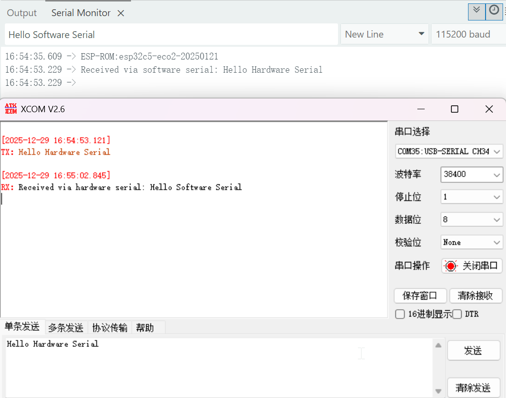
Result
- Wiring Diagram
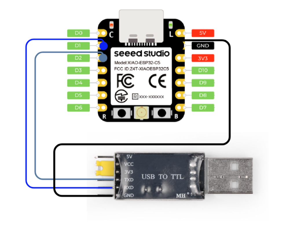
- After uploading the program, connect the board to any serial tool, configure the corresponding baud rate, and then two-way communication can be established.
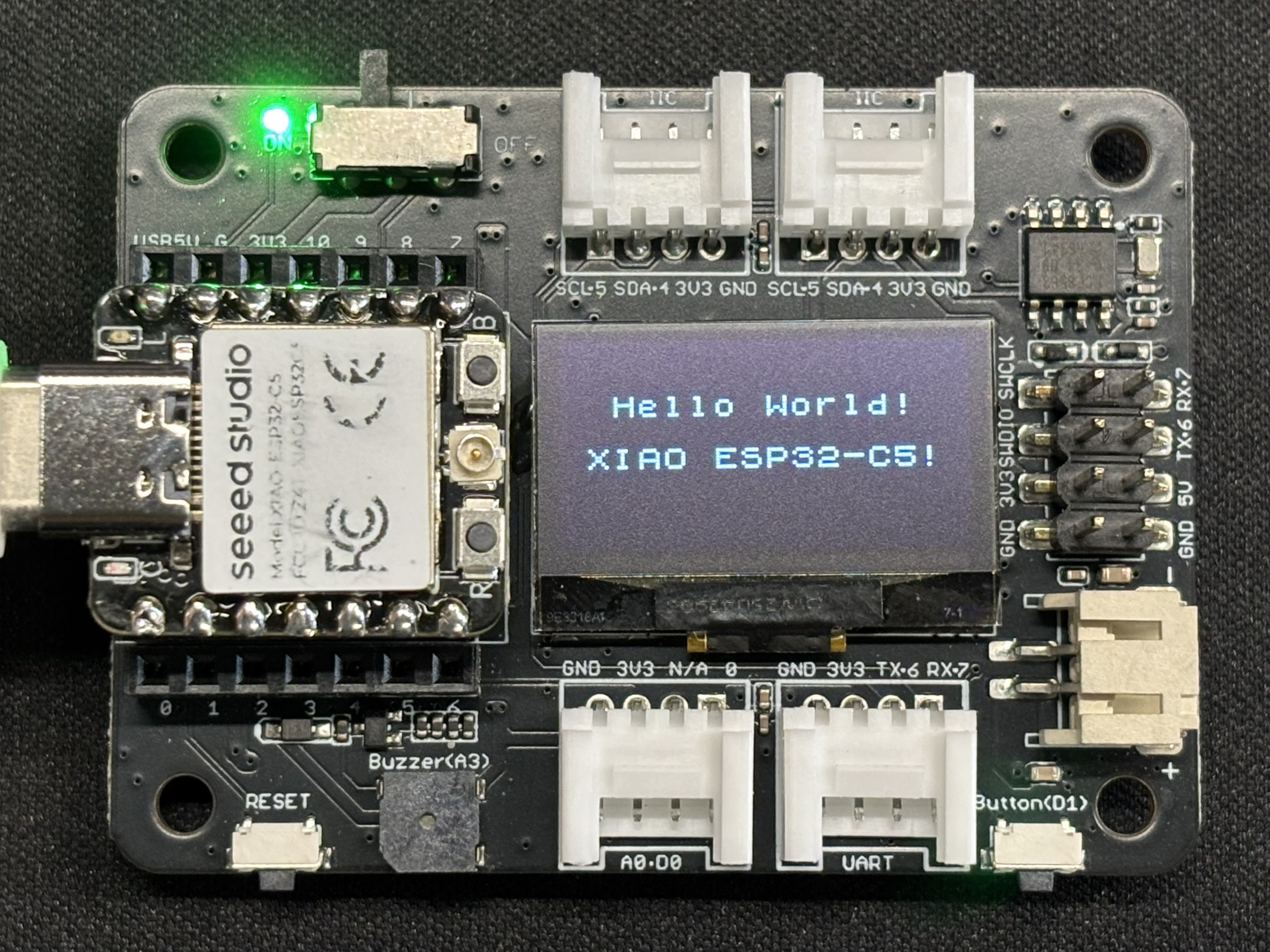
I2C
The XIAO ESP32-C5 chip integrates an I2C interface, which can be used to connect external I2C devices such as flash memory, displays, and sensors. Next, we will demonstrate the usage of I2C with the Seeed Studio Expansion Board Base for XIAO as an example.
Hardware Preparation
| Seeed Studio XIAO ESP32-C5 | Seeed Studio Expansion Board Base for XIAO |
|---|---|
|  |
Software
The following code examples are based on Arduino IDE and PlatformIO respectively, and they achieve the same display effect. You can select and reuse the appropriate code according to your actual development scenario.
- Arduino IDE
- PlatformIO
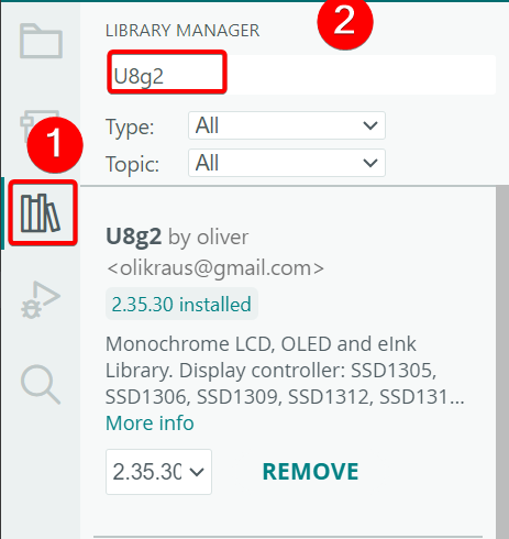
- Install the U8g2 library.
- Reference Code
#include <U8x8lib.h>
#include <Wire.h>

#define SCL D5
#define SDA D4

U8X8_SSD1306_128X64_NONAME_HW_I2C u8x8(/* clock=*/ SCL, /* data=*/ SDA, /* reset=*/ U8X8_PIN_NONE);   // OLEDs without Reset of the Display

void setup(void) {
  u8x8.begin();
  u8x8.setFlipMode(0);
}

void loop(void) {
  u8x8.setFont(u8x8_font_chroma48medium8_r);

  u8x8.setCursor(2, 10);
  u8x8.print("Hello World!");
  u8x8.setCursor(1, 28);
  u8x8.print("XIAO ESP32-C5!");
}
- Ensure the content of
platform.iniis as follows.
[env:seeed-xiao-esp32-c5]
platform = Seeed Studio
board = seeed-xiao-esp32-c5
framework = arduino
lib_deps =
	olikraus/U8g2@^2.36.15
- Reference Code
#include <Arduino.h>
#include <U8x8lib.h>
#include <Wire.h>

#define SCL D5
#define SDA D4

U8X8_SSD1306_128X64_NONAME_HW_I2C u8x8(/* clock=*/ SCL, /* data=*/ SDA, /* reset=*/ U8X8_PIN_NONE);   // OLEDs without Reset of the Display

void setup(void) {
  u8x8.begin();
  u8x8.setFlipMode(0);
}

void loop(void) {
  u8x8.setFont(u8x8_font_chroma48medium8_r);

  u8x8.setCursor(2, 10);
  u8x8.print("Hello World!");
  u8x8.setCursor(1, 28);
  u8x8.print("XIAO ESP32-C5!");
}
Result
- After uploading the program, the text
Hello World!andXIAO ESP32-C5!will be displayed on the screen.
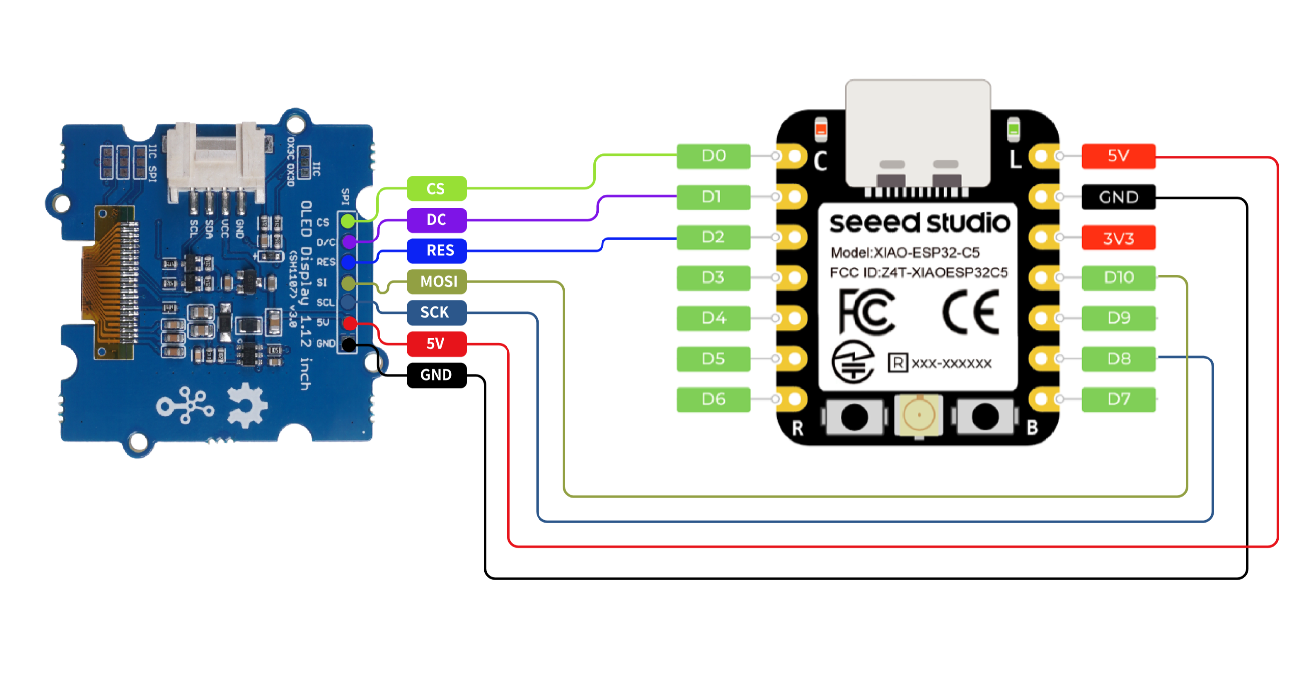
SPI
The XIAO ESP32-C5 chip integrates an SPI interface, which can be used to connect external SPI devices such as flash memory, displays, and sensors. This example demonstrates the functionality of SPI using an SPI screen.
Hardware Preparation
| Seeed Studio XIAO ESP32-C5 | Grove - OLED Display 1.12 (SH1107) V3.0 - SPI/IIC |
|---|---|
|  |
Software
The following code snippets are based on Arduino IDE and PlatformIO respectively, and they achieve the same display effect. You can select and reuse the appropriate code according to your actual development needs.
- Arduino IDE
- PlatformIO
- Install the U8g2 library.
- Reference Code
#include <U8g2lib.h>
#include <SPI.h>
#include <Wire.h>

U8G2_SH1107_128X128_1_4W_HW_SPI u8g2(U8G2_R3,
  /* cs=*/    D0,
  /* dc=*/    D1,
  /* reset=*/ D2);

void setup(void) {
  u8g2.begin();
}

void loop(void) {
  const char* msg = "Hello XIAO ESP32-C5";

  u8g2.firstPage();
  do {
    u8g2.setFont(u8g2_font_luBIS08_tf);

    int16_t w = u8g2.getStrWidth(msg);
    int16_t x = (128 - w) / 2;

    int16_t ascent  = u8g2.getAscent();
    int16_t descent = u8g2.getDescent();
    int16_t h = ascent - descent;
    int16_t y = (128 - h) / 2 + ascent;

    u8g2.drawStr(x, y, msg);
  } while (u8g2.nextPage());
}
- Ensure the content of
platform.iniis as follows.
[env:seeed-xiao-esp32-c5]
platform = Seeed Studio
board = seeed-xiao-esp32-c5
framework = arduino
lib_deps =
  olikraus/U8g2@^2.36.15
- Reference Code
#include <Arduino.h>
#include <U8g2lib.h>
#include <SPI.h>
#include <Wire.h>

U8G2_SH1107_128X128_1_4W_HW_SPI u8g2(U8G2_R3,
  /* cs=*/    D0,
  /* dc=*/    D1,
  /* reset=*/ D2);

void setup(void) {
  u8g2.begin();
}

void loop(void) {
  const char* msg = "Hello XIAO ESP32-C5";

  u8g2.firstPage();
  do {
    u8g2.setFont(u8g2_font_luBIS08_tf);

    int16_t w = u8g2.getStrWidth(msg);
    int16_t x = (128 - w) / 2;

    int16_t ascent  = u8g2.getAscent();
    int16_t descent = u8g2.getDescent();
    int16_t h = ascent - descent;
    int16_t y = (128 - h) / 2 + ascent;

    u8g2.drawStr(x, y, msg);
  } while (u8g2.nextPage());
}
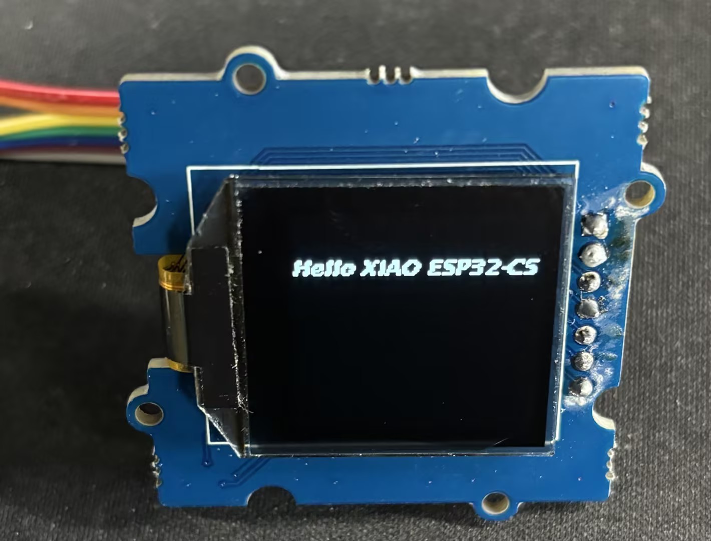
Result
- Wiring Diagram
- After uploading the code, the text Hello XIAO ESP32-C5 will be displayed on the screen.
Tech Support & Product Discussion
Thank you for choosing our products! We are here to provide you with different support to ensure that your experience with our products is as smooth as possible. We offer several communication channels to cater to different preferences and needs.