XIAO ESP32-C5 With Zephyr(RTOS)
The Zephyr OS is based on a small-footprint kernel designed for use on resource-constrained and embedded systems: from simple embedded environmental sensors and LED wearables to sophisticated embedded controllers, smart watches, and IoT wireless applications.
Getting Started
Hardware Preparation
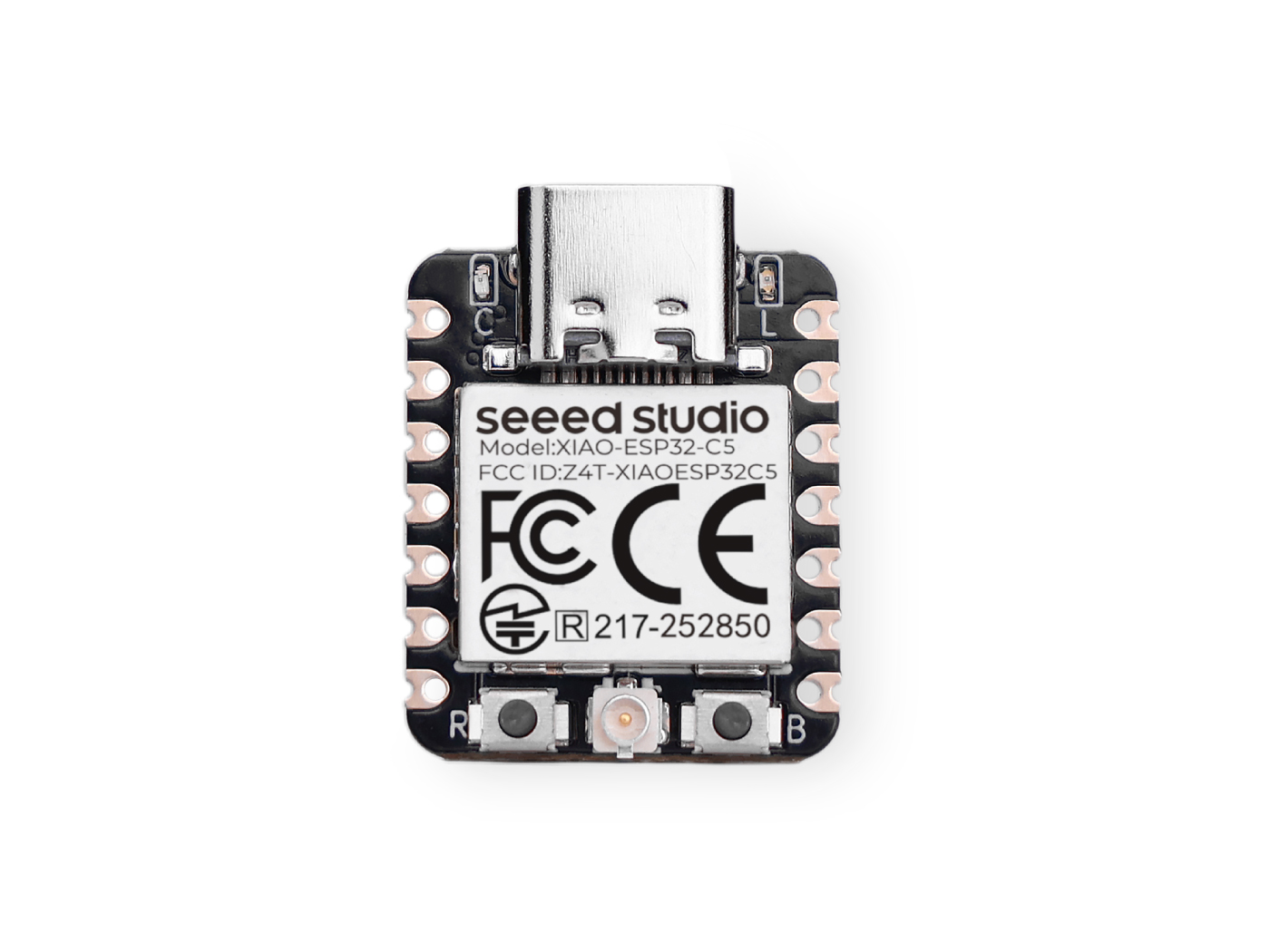
Please prepare one XIAO ESP32-C5 board to support the following verification and related work.
| Seeed Studio XIAO ESP32-C5 |
|---|
 |
Software Preparation
This article is developed and verified based on Ubuntu 24.04 LTS. Please refer to the relevant documentation for deploying the development environment on Ubuntu, Mac, and Windows. Zephyr Getting Started Guide
It is officially recommended to use Ubuntu 24.04 LTS and later versions, which can effectively avoid troubles caused by environmental dependency issues and save your time.
- Activate the virtual environment.
Create a new virtual environment:
python3 -m venv ~/zephyrproject/.venv
Activate the virtual environment:
source ~/zephyrproject/.venv/bin/activate
- Open the blinky folder.
cd ~/zephyrproject/zephyr/samples/basic/blinky
- Update the overlay file and the prj.conf file.
The default serial port log output is mapped to GPIO11 and GPIO12 ,corresponding to D6 and D7 on XIAO ESP32‑C5. To use USB Serial/JTAG for log output, you need to remap the serial port pins to the corresponding pins of USB Serial/JTAG. Meanwhile, according to the hardware design of XIAO ESP32‑C5, you must also configure the user LED pin to GPIO27.
If you are not familiar with the pinout of the XIAO ESP32-C5, you can check Pinlist
Create a new overlay file
nano ~/zephyrproject/zephyr/samples/basic/blinky/boards/esp32c5_devkitc_esp32c5_hpcore.overlay
Add the overlay content
After adding the content, press Ctrl + O to save the file, then Ctrl + X to exit.
Modify the content of prj.conf
nano ~/zephyrproject/zephyr/samples/basic/blinky/boards/prj.conf
Modify the content to the following, mainly adjusting the UART mapping relationship.
CONFIG_USB_DEVICE_STACK=y
CONFIG_USB_CDC_ACM=y
CONFIG_UART_LINE_CTRL=y
CONFIG_GPIO=y
CONFIG_LOG=y
- Set the target board to esp32c5_devkitc and start compiling.
hpcore stands for High Performance Core. It is usually used to run main programs and tasks with high performance requirements.
west build -p always -b esp32c5_devkitc/esp32c5/hpcore ~/zephyrproject/zephyr/samples/basic/blinky
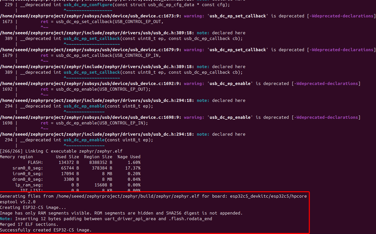
Successful Compilation Symptoms
- Flash the device
Before flashing the program to the device, the XIAO ESP32-C5 must be set to Bootloader Download Mode.
Method: Press and hold the BOOT button, then power on the device.
Check the serial port device. The device is usually /dev/ttyACM0.
ls /dev/ttyACM*

Due to access permission restrictions on the serial port device file, it is necessary to modify its permissions to support read and write operations.
sudo chmod 666 /dev/ttyACM0
Specify the serial port device and start downloading.
west flash --esp-device /dev/ttyACM0
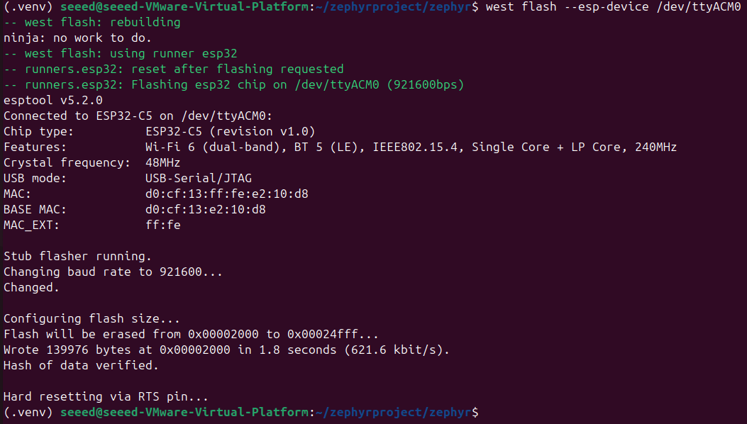
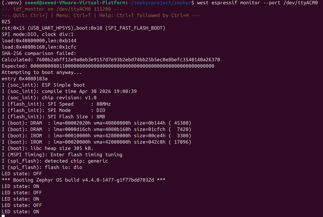
Sample Output for Successful Download
- Phenomenon Demonstration
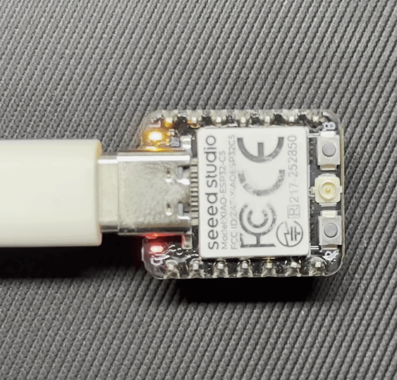
After downloading successfully, the LED will start blinking.
Open Serial Port, and log information of LED ON or LED OFF will be printed.
west espressif monitor --port /dev/ttyACM0
Application
The XIAO ESP32-C5 supports the use of expansion boards compatible with the XIAO series, enabling easy expansion of peripherals and application scenarios.
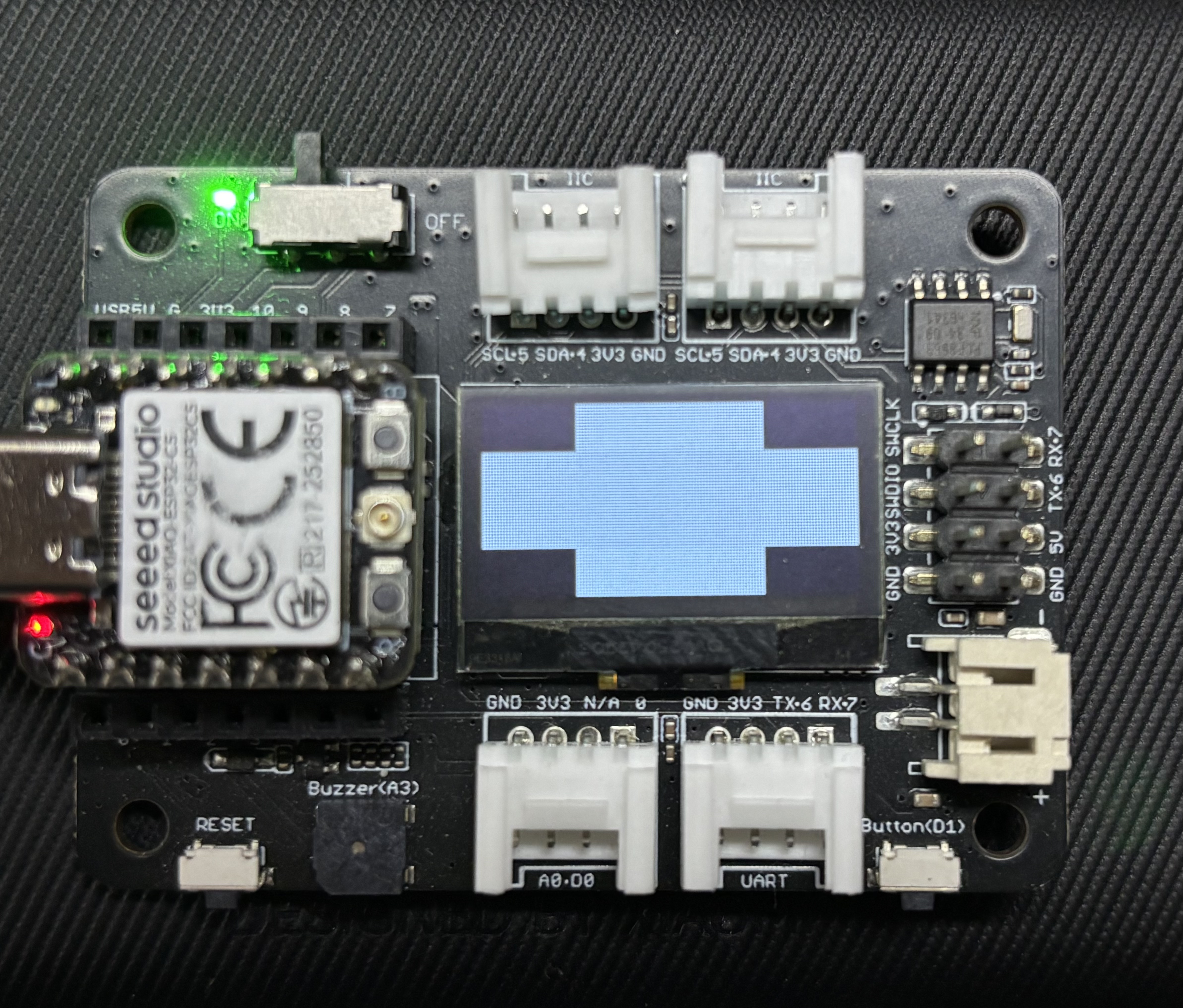
Using the Expansion Board Base for XIAO
Expansion Board Base for XIAO is equipped with an IIC interface and an onboard 0.96-inch OLED screen.
Hardware Preparation
| Seeed Studio XIAO ESP32-C5 | Seeed Studio Expansion Board Base for XIAO with Grove OLED |
|---|---|
|  |
Software Preparation
According to the pin definition of the XIAO ESP32-C5, GPIO23 corresponds to SDA, which is D4; GPIO24 corresponds to SCL, which is D5. It is necessary to create and modify the content of the device tree node.
- Open the display example.
cd ~/zephyrproject/zephyr/samples/drivers/display
- Add the overlay file.
nano esp32c5_devkitc_esp32c5_hpcore.overlay
Add the device tree node content.
#include <zephyr/dt-bindings/pinctrl/esp32c5-pinctrl.h>
#include <zephyr/dt-bindings/i2c/i2c.h>

&pinctrl {
    i2c0_custom: i2c0_custom {
        group1 {
            pinmux = <I2C0_SDA_GPIO23>,
                     <I2C0_SCL_GPIO24>;
            bias-pull-up;
            drive-open-drain;
            output-high;
        };
    };
};

&i2c0 {
    status = "okay";
    clock-frequency = <I2C_BITRATE_FAST>;
    pinctrl-0 = <&i2c0_custom>;
    pinctrl-names = "default";

    ssd1306_128x64: ssd1306@3c {
        compatible = "solomon,ssd1306";
        reg = <0x3c>;
        width = <128>;
        height = <64>;
        segment-offset = <0>;
        page-offset = <0>;
        display-offset = <0>;
        multiplex-ratio = <63>;
        segment-remap;
        com-invdir;
        prechargep = <0x22>;
    };
};

/ {
    chosen {
        zephyr,display = &ssd1306_128x64;
    };
};
- Compile and flash
west build -p always -b esp32c5_devkitc/esp32c5/hpcore   ~/zephyrproject/zephyr/samples/drivers/display

sudo chmod 666 /dev/ttyACM0

west flash
Result
The Expansion Board Base for XIAO will display a screen effect.
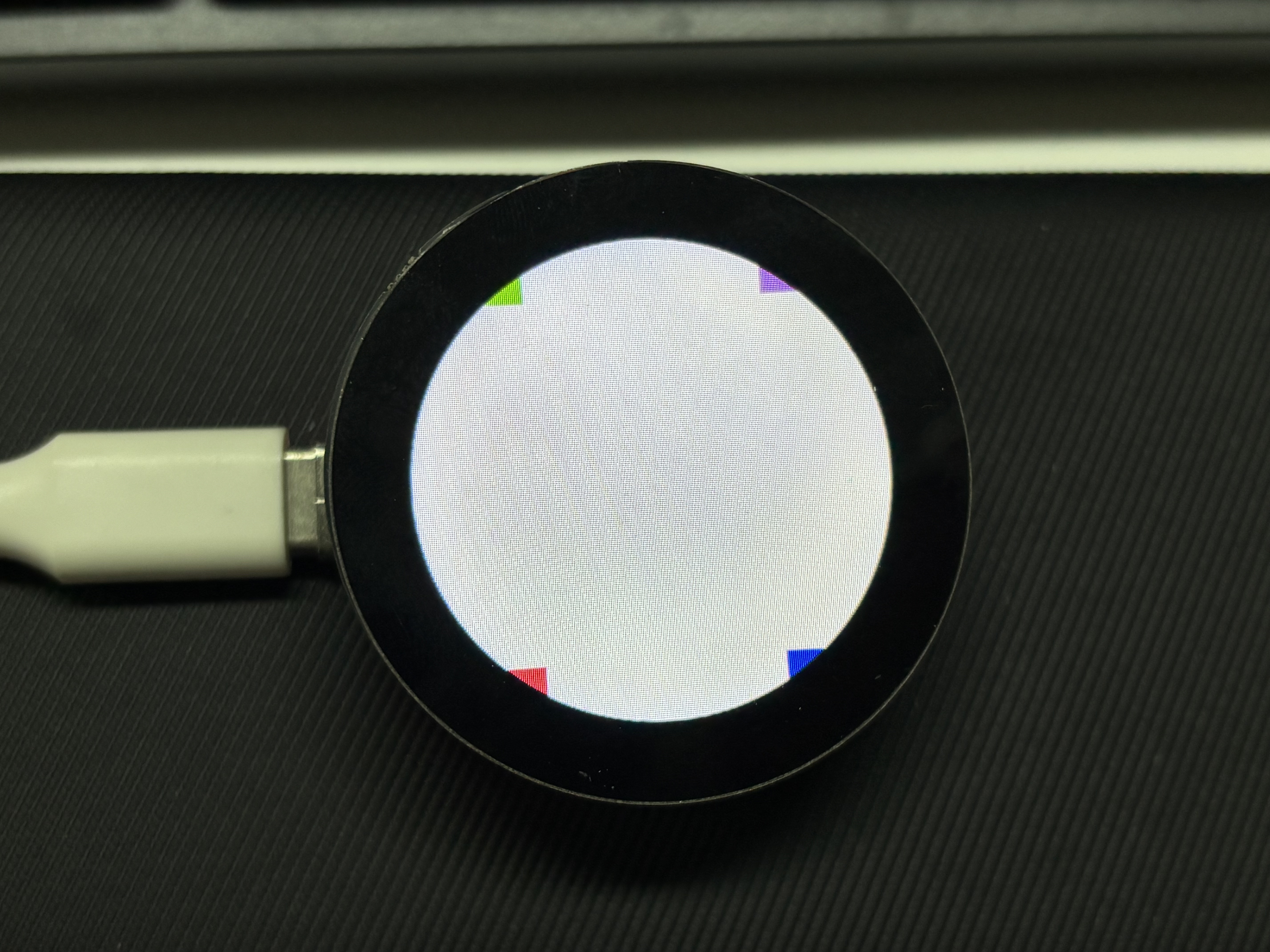
Using the Round Display for Seeed Studio XIAO
Round Display for Seeed Studio XIAO is a round display specially designed for the XIAO series. It is equipped with the GC9A01 driver chip onboard and adopts the standard SPI communication protocol.
Hardware Preparation
| Seeed Studio XIAO ESP32-C5 | Round Display for Seeed Studio XIAO |
|---|---|
|  |
Software Preparation
- Open the display example.
cd ~/zephyrproject/zephyr/samples/drivers/display
- Add the overlay file.
nano esp32c5_devkitc_esp32c5_hpcore.overlay
Add the device tree node content.
esp32c5_devkitc_esp32c5_hpcore.overlay
/*
 * Copyright (c) 2026
 * SPDX-License-Identifier: Apache-2.0
 *
 * Standalone overlay for GC9A01 round display on XIAO ESP32-C5.
 * Does not depend on seeed_xiao_round_display shield.
 *
 * Pin mapping (XIAO ESP32-C5):
 *   D1  = GPIO0  -> display CS  (active low)
 *   D2  = GPIO25 -> SD card CS  (active low)
 *   D3  = GPIO7  -> display DC  (active high)
 *   D4  = GPIO23 -> SDA
 *   D5  = GPIO24 -> SCL
 *   D6  = GPIO11 -> TX (disabled, reused for backlight control)
 *   D7  = GPIO12 -> touch IRQ   (active low)
 *   D8  = GPIO8  -> SCK
 *   D9  = GPIO9  -> MISO
 *   D10 = GPIO10 -> MOSI
 */

#include <freq.h>
#include <zephyr/dt-bindings/pinctrl/esp32c5-pinctrl.h>
#include <zephyr/dt-bindings/display/panel.h>

/ {
    chosen {
        zephyr,display = &gc9a01_round_display;
        zephyr,touch = &chsc6x_round_display;
    };

    lvgl_pointer {
        compatible = "zephyr,lvgl-pointer-input";
        input = <&chsc6x_round_display>;
    };

    vbatt {
        compatible = "voltage-divider";
        io-channels = <&adc0 0>;
        output-ohms = <470000>;
        full-ohms = <940000>;
    };

    aliases {
        rtc = &pcf8563_round_display;
    };
};

&pinctrl {
    /* I2C0: SDA = GPIO23 (D4), SCL = GPIO24 (D5) */
    i2c0_custom: i2c0_custom {
        group1 {
            pinmux = <I2C0_SDA_GPIO23>,
                     <I2C0_SCL_GPIO24>;
            bias-pull-up;
            drive-open-drain;
            output-high;
        };
    };

    /* SPI2: SCK = GPIO8 (D8), MISO = GPIO9 (D9), MOSI = GPIO10 (D10) */
    spim2_custom: spim2_custom {
        group1 {
            pinmux = <SPIM2_MISO_GPIO9>,
                     <SPIM2_SCLK_GPIO8>;
        };
        group2 {
            pinmux = <SPIM2_MOSI_GPIO10>;
            output-low;
        };
    };
};

/* D6 = GPIO11 reused for backlight, disable UART TX */
&uart0 {
    status = "disabled";
};

&adc0 {
    status = "okay";
};

&i2c0 {
    status = "okay";
    clock-frequency = <I2C_BITRATE_FAST>;
    pinctrl-0 = <&i2c0_custom>;
    pinctrl-names = "default";

    /* RTC, address 0x51 */
    pcf8563_round_display: pcf8563@51 {
        status = "okay";
        compatible = "nxp,pcf8563";
        reg = <0x51>;
    };

    /* Touch controller, IRQ = GPIO12 (D7) */
    chsc6x_round_display: chsc6x@2e {
        status = "okay";
        compatible = "chipsemi,chsc6x";
        reg = <0x2e>;
        irq-gpios = <&gpio0 12 GPIO_ACTIVE_LOW>;
        screen-width = <240>;
        screen-height = <240>;
    };
};

&spi2 {
    status = "okay";
    pinctrl-0 = <&spim2_custom>;
    pinctrl-names = "default";
    /* D1 = GPIO0  -> display CS
     * D2 = GPIO25 -> SD card CS */
    cs-gpios = <&gpio0 0  GPIO_ACTIVE_LOW>,
               <&gpio0 25 GPIO_ACTIVE_LOW>;

    /* MIPI DBI SPI wrapper for GC9A01, DC = GPIO7 (D3) */
    round_display_mipi_dbi: mipi_dbi {
        compatible = "zephyr,mipi-dbi-spi";
        spi-dev = <&spi2>;
        dc-gpios = <&gpio0 7 GPIO_ACTIVE_HIGH>;
        write-only;
        #address-cells = <1>;
        #size-cells = <0>;

        gc9a01_round_display: gc9a01@0 {
            status = "okay";
            compatible = "galaxycore,gc9x01x";
            reg = <0>;
            mipi-max-frequency = <DT_FREQ_M(100)>;
            pixel-format = <PANEL_PIXEL_FORMAT_RGB_565>;
            width = <240>;
            height = <240>;
            display-inversion;
        };
    };

    /* SD card slot, CS = GPIO25 (D2) */
    sdhc_round_display: sdhc@1 {
        compatible = "zephyr,sdhc-spi-slot";
        reg = <1>;
        status = "okay";
        spi-max-frequency = <DT_FREQ_M(24)>;
        mmc {
            compatible = "zephyr,sdmmc-disk";
            disk-name = "SD";
            status = "okay";
        };
    };
};
- Compile and flash
west build -p always -b esp32c5_devkitc/esp32c5/hpcore   ~/zephyrproject/zephyr/samples/drivers/display

sudo chmod 666 /dev/ttyACM0

west flash
Result
After flashing the firmware, press the key, and the screen content will be displayed on the Round Display for Seeed Studio XIAO.
Conclusion
I believe by now you have basically mastered Zephyr development on the XIAO ESP32-C5. If you have any creative ideas, feel free to develop your projects and share them with the community, letting others see your excellent works.
Tech Support & Product Discussion
Thank you for choosing our products! We are here to provide you with different support to ensure that your experience with our products is as smooth as possible. We offer several communication channels to cater to different preferences and needs.