Seeed Studio XIAO ESP32C5 Zigbee Quick Start Guide (Arduino)
This tutorial guides you through implementing Zigbee applications on the Seeed Studio XIAO ESP32-C5 development board, this board combines Wi-Fi, Bluetooth Low Energy (BLE), and Zigbee connectivity, making it perfect for IoT applications. The examples in this guide use the esp-arduino Zigbee SDK to bring Zigbee functionality to life.
If you haven't prepared your Arduino IDE, refer to the Getting Started Guide.
Zigbee Overview
Zigbee is a low-power, low-bandwidth wireless communication protocol based on the IEEE 802.15.4 standard. It is tailored for IoT scenarios such as home automation, smart cities, and industrial control, offering robust mesh networking capabilities for reliable communication in dynamic environments.
- We will provide a brief explanation of Zigbee-related content. If you want to directly refer to the application examples, you can also skip ahead.
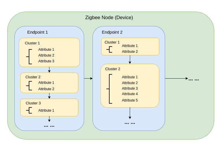
Zigbee Data Model
Zigbee communication relies on the Zigbee Cluster Library (ZCL), which defines how devices organize their functionality and interact. Key components include:
-
Device Types Zigbee devices (e.g., switches, sensors, lights) are pre-defined with specific behaviors, grouped into functional Clusters.
-
Clusters Clusters are logical groupings of:
- Attributes: Represent device states, like brightness or temperature.
- Commands: Trigger actions, such as turning a light on or setting brightness to 50%.
Examples:
- On/Off Cluster: Controls binary states like power.
- Level Control Cluster: Adjusts intensity or brightness.
- Temperature Measurement Cluster: Sends temperature readings.
- Scenes Cluster: Saves and recalls preset configurations.
-
Attributes & Commands Attributes store device data (e.g., state, configuration), while commands initiate actions.
Zigbee Network Architecture
A Zigbee network consists of three primary node types:
-
Zigbee Coordinator (ZC)
- Serves as the central hub of the network.
- Handles network creation, device authentication, and address allocation.
- Responsible for initializing and managing the network.
- Each Zigbee network can have only one Coordinator.
-
Zigbee Router (ZR)
- Extends the network range by relaying messages between devices.
- Supports additional devices joining the network.
- Typically mains-powered to ensure constant operation and reliable message relaying.
- Battery-powered Routers are possible but less common due to higher energy demands.
-
Zigbee End Device (ZED)
- Lightweight and power-efficient devices that communicate with a parent node (either a Coordinator or Router).
- Do not route messages to other devices.
- Optimized for battery operation and typically enter sleep modes to conserve energy.
-
Addressing and Routing:
- Zigbee uses a 16-bit addressing scheme. Devices communicate through a mix of direct and indirect addressing.
- Routing decisions are made by Routers using algorithms like AODV (Ad hoc On-demand Distance Vector).
-
Power Management:
- Zigbee End Devices are optimized for low power consumption. They often operate in sleep mode and only wake when needed.
- Routers and the Coordinator are generally mains-powered for consistent availability.
Network Topologies
Zigbee supports three primary network topologies, depending on the application requirements and environment:
1. Mesh Topology
-
A single Coordinator and multiple Routers form a self-healing, robust network.
-
Devices can dynamically reroute messages if a communication path is disrupted, ensuring high reliability.
-
Ideal for large-scale networks requiring wide coverage and redundancy.
-
Key Features:
- Dynamic rerouting ensures high reliability.
- Supports large networks with scalable coverage.
- Self-healing mechanisms increase fault tolerance.
2. Tree Topology
-
The Coordinator acts as the root of a hierarchical structure, with Routers forming branches.
-
Each branch can have multiple End Devices or additional Routers, creating a tree-like structure.
-
Communication depends on hierarchical paths, which introduces potential single points of failure.
-
Key Features:
- Works well for structured environments.
- Easier to set up and manage than a mesh network.
- Vulnerable to branch failure, which can disconnect entire sub-networks.
3. Star Topology
-
All devices communicate directly with the Coordinator.
-
Simple to deploy, but the Coordinator is a single point of failure.
-
Best suited for small networks where devices are located close to the Coordinator.
-
Key Features:
- Easy to set up and manage.
- Limited scalability due to range and device capacity constraints.
- Reliance on the Coordinator for all communication reduces fault tolerance.
Started with Arduino Zigbee
We will demonstrate the Zigbee networking functionality for you using Zigbee_On_Off_Light and Zigbee_On_Off_Switch on the XIAO ESP32-C5 within the Arduino IDE.
Hardware Preparation
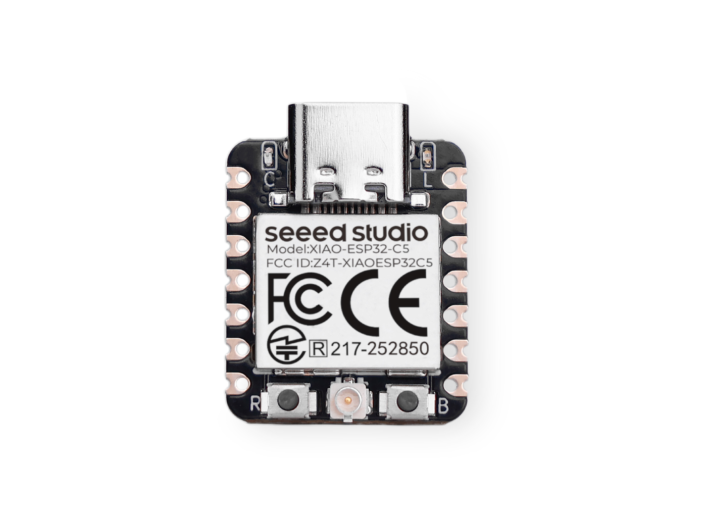
You need to prepare two XIAO ESP32-C5 boards.
| Seeed Studio XIAO ESP32-C5 |
|---|
 |
Zigbee_On_Off_Light
You need to select one XIAO ESP32-C5 as the light bulb device.
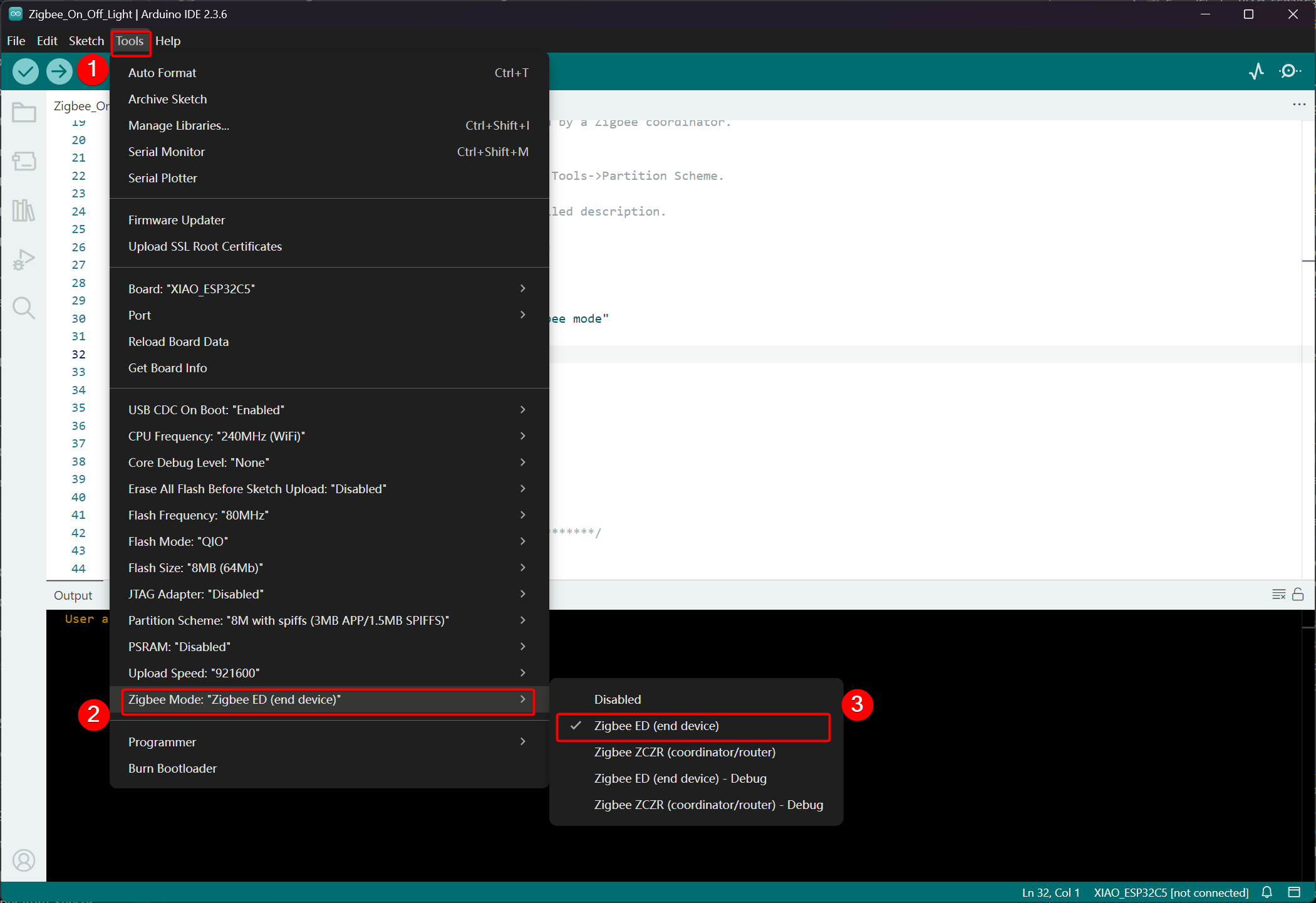
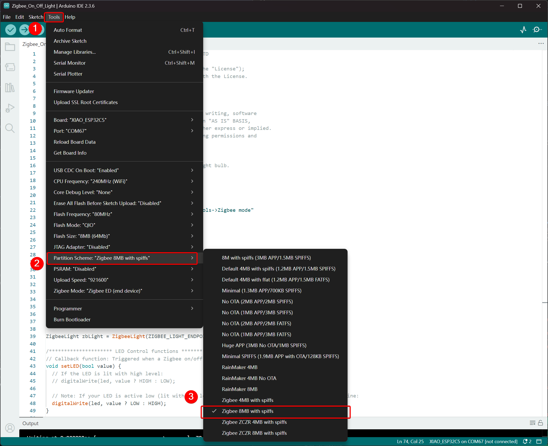
Step 1. Set End Device Mode
We need to set the XIAO ESP32-C5 as a Zigbee End Device.
- Click Tools -> Zigbee Mode and select the mode as Zigbee ED (End Device).
- Select Partition Scheme, go to Tools -> Partition Scheme -> Zigbee 8MB with spiffs
The FLASH memory of the XIAO ESP32-C5 is 8MB. When selecting a partition scheme, it is recommended to choose Zigbee 8MB with spiffs.
Step 2. Write the code
- Refer to the official Arduino repository to obtain examples.
- Alternatively, you can select the example from the Arduino IDE via the path: File -> Examples -> Zigbee -> Zigbee_On_Off_Light.

- Modify the examples
For the XIAO ESP32-C5, we select the onboard LED as the light-emitting bulb, and the control pin is GPIO27.
Zigbee_On_Off_Light.ino
// Copyright 2024 Espressif Systems (Shanghai) PTE LTD
//
// Licensed under the Apache License, Version 2.0 (the "License");
// you may not use this file except in compliance with the License.
// You may obtain a copy of the License at

//     http://www.apache.org/licenses/LICENSE-2.0
//
// Unless required by applicable law or agreed to in writing, software
// distributed under the License is distributed on an "AS IS" BASIS,
// WITHOUT WARRANTIES OR CONDITIONS OF ANY KIND, either express or implied.
// See the License for the specific language governing permissions and
// limitations under the License.

/**
 * @brief This example demonstrates simple Zigbee light bulb.
 *
 * Modified for Single Color LED control.
 */

#ifndef ZIGBEE_MODE_ED
#error "Zigbee end device mode is not selected in Tools->Zigbee mode"
#endif

#include "Zigbee.h"

/* Zigbee light bulb configuration */
#define ZIGBEE_LIGHT_ENDPOINT 10

// =========================================================
// Modification Area: Define your single-color LED pin here
// If your LED is connected to GPIO 2, set it to 2.
// If using the onboard standard LED, LED_BUILTIN can usually be used
// =========================================================
uint8_t led = 27;  // <--- Please modify the number here to your actual GPIO pin number

uint8_t button = BOOT_PIN;

ZigbeeLight zbLight = ZigbeeLight(ZIGBEE_LIGHT_ENDPOINT);

/********************* LED Control functions **************************/
// Callback function: Triggered when a Zigbee on/off command is received
void setLED(bool value) {
  // If the LED is lit with high level:
  // digitalWrite(led, value ? HIGH : LOW);

  // Note: If your LED is active low (lit with low level), use the line below instead of the above line:
  digitalWrite(led, value ? LOW : HIGH);
}

/********************* Arduino functions **************************/
void setup() {
  Serial.begin(115200);

  // Initialize LED pin as output mode
  pinMode(led, OUTPUT);
  // Turn off LED by default (assuming low level means on)
  digitalWrite(led, LOW);

  // Initialize button for factory reset
  pinMode(button, INPUT_PULLUP);

  // Optional: Set Zigbee device name and model (will be displayed in Home Assistant)
  zbLight.setManufacturerAndModel("Espressif", "SingleColorLight");

  // Set callback function for light state change
  zbLight.onLightChange(setLED);

  // Add Endpoint to Zigbee core
  Serial.println("Adding ZigbeeLight endpoint to Zigbee Core");
  Zigbee.addEndpoint(&zbLight);

  // Start Zigbee
  if (!Zigbee.begin()) {
    Serial.println("Zigbee failed to start!");
    Serial.println("Rebooting...");
    ESP.restart();
  }
  Serial.println("Connecting to network");
  while (!Zigbee.connected()) {
    Serial.print(".");
    delay(100);
  }
  Serial.println();
}

void loop() {
  // Check button for factory reset
  if (digitalRead(button) == LOW) {  // Button is pressed
    // Button debounce
    delay(100);
    int startTime = millis();
    while (digitalRead(button) == LOW) {
      delay(50);
      if ((millis() - startTime) > 3000) {
        // If pressed for more than 3 seconds, reset Zigbee and reboot
        Serial.println("Resetting Zigbee to factory and rebooting in 1s.");
        delay(1000);
        Zigbee.factoryReset();
      }
    }
    // Short press of the button: Toggle light state (local control)
    zbLight.setLight(!zbLight.getLightState());
  }
  delay(100);
}
- Upload the code. Since it is set to turn on at low level by default, press the reset button after uploading the code, and the onboard LED will light up.
Implementation Logic
- Mode Check
#ifndef ZIGBEE_MODE_ED
#error "Zigbee end device mode is not selected..."
#endif
This forces the selection of "End Device" mode in Tools → Zigbee mode of the Arduino IDE. Zigbee light bulbs typically act as low-power End Devices, rather than Routers or Coordinators.
- Include Header File
#include "Zigbee.h"
Imports the core Zigbee library provided by Espressif, which contains all Zigbee-related classes and functions.
- Configuration Definition
#define ZIGBEE_LIGHT_ENDPOINT 10
Defines the Zigbee Endpoint number as 10. A Zigbee device can have multiple endpoints, and the bulb functionality is assigned to endpoint 10 here.
- User-Modifiable Area (Most Important Part)
uint8_t led = 27;        // Modify this to the actual GPIO pin connected to your LED
uint8_t button = BOOT_PIN;  // Usually GPIO0, used for factory reset
-
led = 27: The GPIO pin that controls the monochromatic LED. Please modify this number according to your hardware wiring. -
button = BOOT_PIN: Usually the BOOT button (GPIO0) on the ESP32 development board, used to reset the Zigbee configuration with a long press.
- Create Zigbee Light Bulb Object
ZigbeeLight zbLight = ZigbeeLight(ZIGBEE_LIGHT_ENDPOINT);
Creates a Zigbee Light object that implements the standard Zigbee HA (Home Automation) OnOff Cluster for light bulbs, supporting remote on/off control.
- LED Control Callback Function
void setLED(bool value) {
  digitalWrite(led, value ? LOW : HIGH);
}
This function is automatically called when an on/off command is received from the Zigbee network.
- The current code assumes your LED is active low (common when an external LED on an ESP32 development board is connected to GND via a resistor).
- If your LED is active high (e.g., directly connected to VCC and lit by pulling the GPIO low), modify it to the commented line below:
digitalWrite(led, value ? HIGH : LOW);
- Detailed Explanation of setup() Function
void setup() {
  Serial.begin(115200);                    // Enable serial debugging with baud rate 115200

  pinMode(led, OUTPUT);                    // Set the LED pin as output
  digitalWrite(led, LOW);                  // Turn off the LED by default (assuming active low, write LOW to ensure it's off)

  pinMode(button, INPUT_PULLUP);           // Set the button pin as input with pull-up resistor

  zbLight.setManufacturerAndModel("Espressif", "SingleColorLight");
  // Set the device manufacturer and model for friendly display on platforms like Home Assistant

  zbLight.onLightChange(setLED);
  // Key step: Bind the callback function for switch state changes, which calls setLED() when a Zigbee command is received

  Zigbee.addEndpoint(&zbLight);
  // Add the bulb endpoint to the Zigbee core

  if (!Zigbee.begin()) { ... ESP.restart(); }
  // Start the Zigbee stack; restart if it fails

  while (!Zigbee.connected()) { ... }
  // Wait for successful joining of the Zigbee network (pairing completed), print a dot every 100ms
}
- Detailed Explanation of loop() Function
void loop() {
  if (digitalRead(button) == LOW) {        // Detect button press (low level)
    delay(100);                            // Simple debounce
    int startTime = millis();

    while (digitalRead(button) == LOW) {   // Continuously detect if the button is still pressed
      if ((millis() - startTime) > 3000) { // Long press for more than 3 seconds
        Zigbee.factoryReset();             // Factory reset Zigbee configuration (clear pairing information)
        delay(1000);
        // The device will automatically restart and enter pairing mode again
      }
    }

    // If short press: manually control the light's on/off state locally
    zbLight.setLight(!zbLight.getLightState());
    // This triggers the callback setLED() simultaneously to turn the light on/off locally
  }

  delay(100);
}
Zigbee_On_Off_Switch
Select another XIAO ESP32-C5 as the switch. It will form a Zigbee network with the previous light bulb device and then control the on/off state of the bulb.
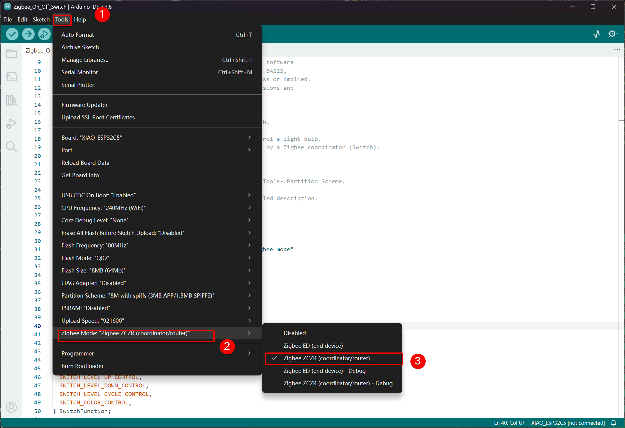
Step 1. Set to Coordinator Mode
- Click Tools -> Zigbee Mode and select the mode as Zigbee ZCZR (Coordinator/Router).
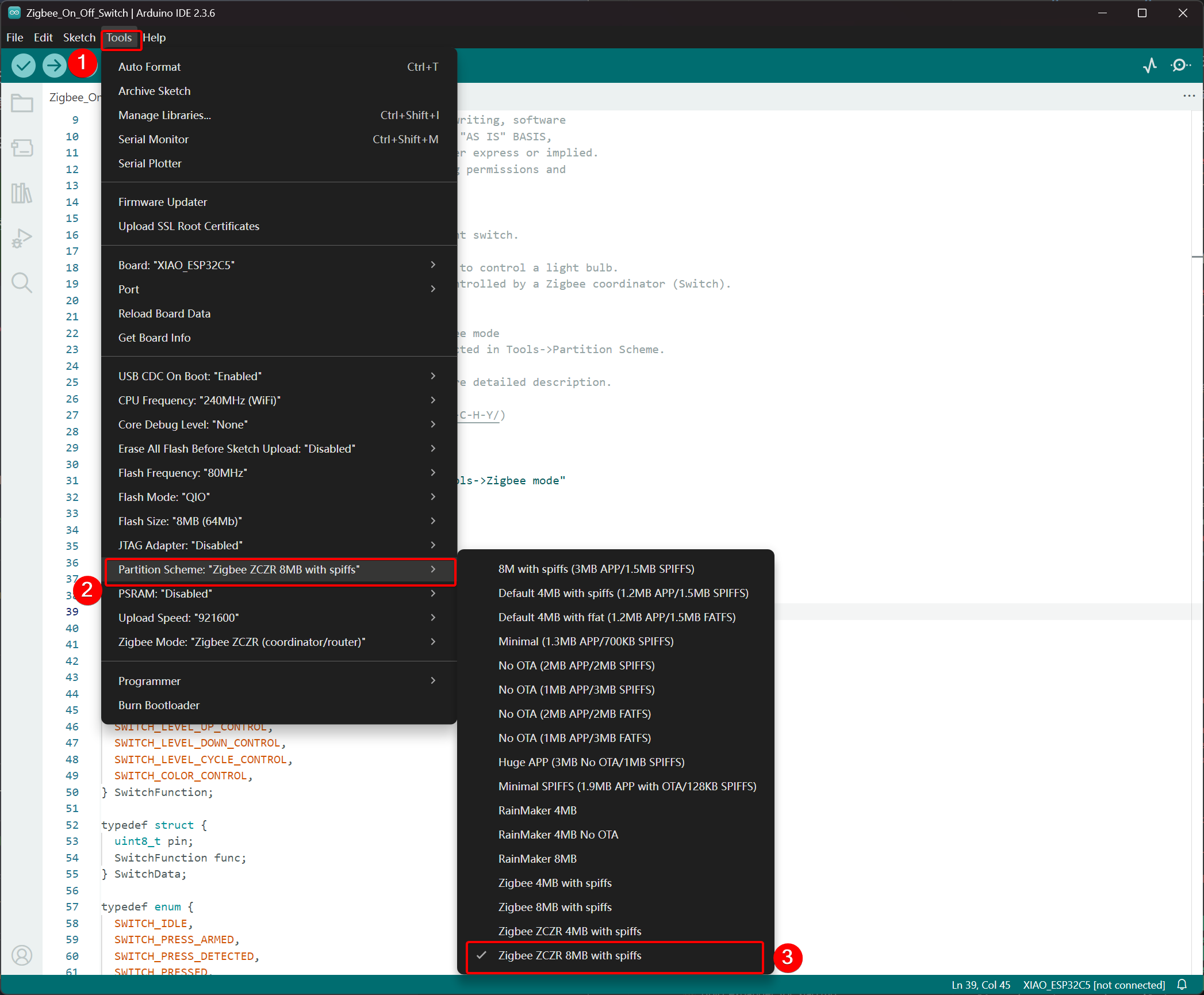
- Select Partition Scheme,go to Tools -> Partition Scheme and choose Zigbee 8MB ZCZR with spiffs.
The FLASH memory of the XIAO ESP32-C5 is 8MB. When selecting a partition scheme, it is recommended to choose Zigbee 8MB ZCZR with spiffs.
Step 2. Write the code
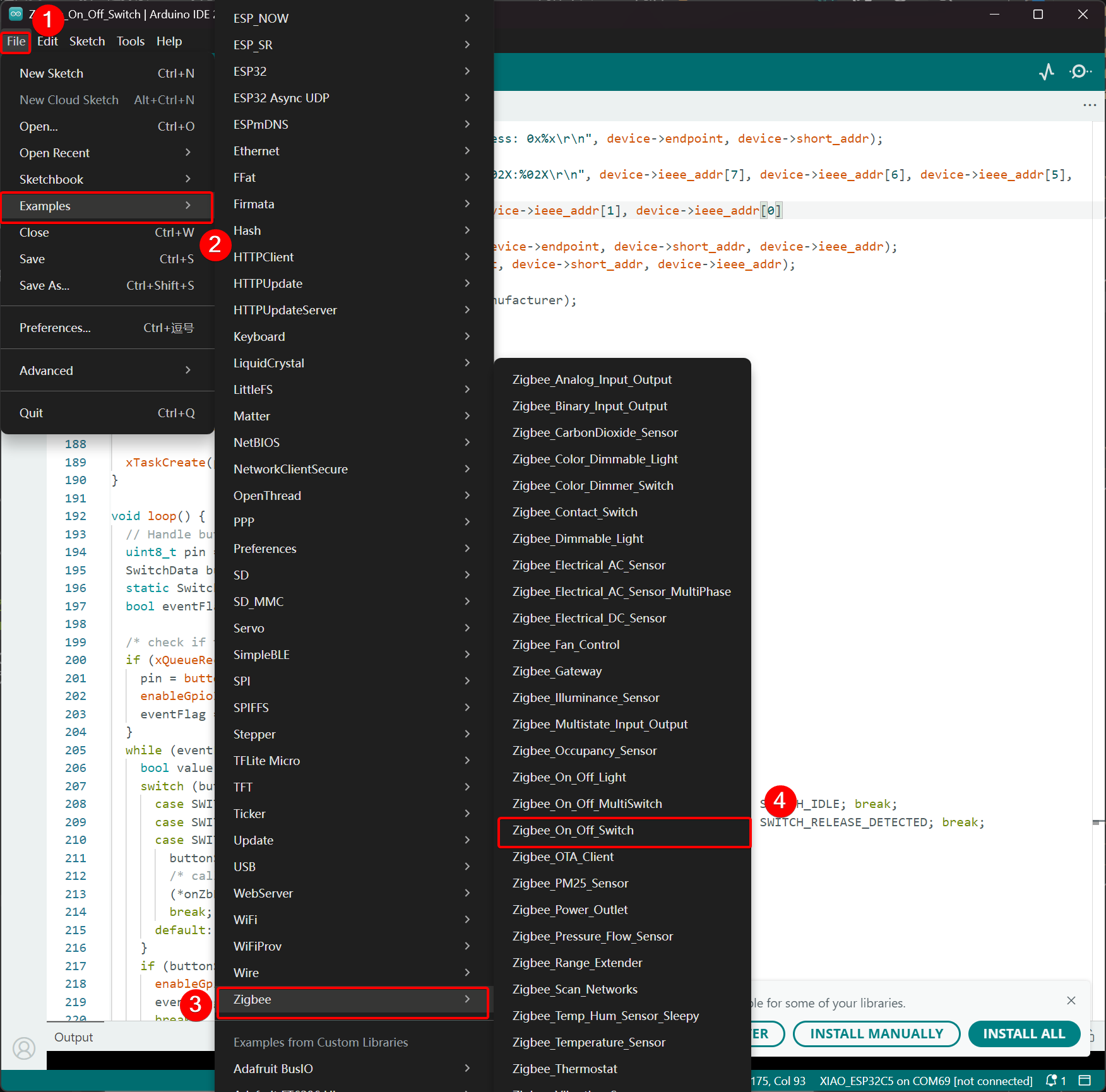
- Skip to the official Arduino repository to obtain the example code.
- Alternatively, you can select the example from the Arduino IDE via the path: File -> Examples -> Zigbee -> Zigbee_On_Off_Swicth.
- We select the BOOT button as the switch. For the XIAO ESP32-C5, the BOOT button corresponds to the GPIO28 pin.
Zigbee_On_Off_Switch.ino
// Copyright 2024 Espressif Systems (Shanghai) PTE LTD
//
// Licensed under the Apache License, Version 2.0 (the "License");
// you may not use this file except in compliance with the License.
// You may obtain a copy of the License at
//
//     http://www.apache.org/licenses/LICENSE-2.0
//
// Unless required by applicable law or agreed to in writing, software
// distributed under the License is distributed on an "AS IS" BASIS,
// WITHOUT WARRANTIES OR CONDITIONS OF ANY KIND, either express or implied.
// See the License for the specific language governing permissions and
// limitations under the License.

/**
 * @brief This example demonstrates simple Zigbee light switch.
 *
 * The example demonstrates how to use Zigbee library to control a light bulb.
 * The light bulb is a Zigbee end device, which is controlled by a Zigbee coordinator (Switch).
 * Button switch and Zigbee runs in separate tasks.
 *
 * Proper Zigbee mode must be selected in Tools->Zigbee mode
 * and also the correct partition scheme must be selected in Tools->Partition Scheme.
 *
 * Please check the README.md for instructions and more detailed description.
 *
 * Created by Jan Procházka (https://github.com/P-R-O-C-H-Y/)
 */

#ifndef ZIGBEE_MODE_ZCZR
#error "Zigbee coordinator mode is not selected in Tools->Zigbee mode"
#endif

#include "Zigbee.h"

/* Zigbee switch configuration */
#define SWITCH_ENDPOINT_NUMBER 5

#define GPIO_INPUT_IO_TOGGLE_SWITCH BOOT_PIN
#define PAIR_SIZE(TYPE_STR_PAIR)    (sizeof(TYPE_STR_PAIR) / sizeof(TYPE_STR_PAIR[0]))

typedef enum {
  SWITCH_ON_CONTROL,
  SWITCH_OFF_CONTROL,
  SWITCH_ONOFF_TOGGLE_CONTROL,
  SWITCH_LEVEL_UP_CONTROL,
  SWITCH_LEVEL_DOWN_CONTROL,
  SWITCH_LEVEL_CYCLE_CONTROL,
  SWITCH_COLOR_CONTROL,
} SwitchFunction;

typedef struct {
  uint8_t pin;
  SwitchFunction func;
} SwitchData;

typedef enum {
  SWITCH_IDLE,
  SWITCH_PRESS_ARMED,
  SWITCH_PRESS_DETECTED,
  SWITCH_PRESSED,
  SWITCH_RELEASE_DETECTED,
} SwitchState;

static SwitchData buttonFunctionPair[] = {{GPIO_INPUT_IO_TOGGLE_SWITCH, SWITCH_ONOFF_TOGGLE_CONTROL}};

ZigbeeSwitch zbSwitch = ZigbeeSwitch(SWITCH_ENDPOINT_NUMBER);

static bool light_state = false;

/********************* Zigbee functions **************************/
static void onZbButton(SwitchData *button_func_pair) {
  if (button_func_pair->func == SWITCH_ONOFF_TOGGLE_CONTROL) {
    // Send toggle command to the light
    Serial.println("Toggling light");
    zbSwitch.lightToggle();
  }
}

static void onLightStateChange(bool state) {
  if (state != light_state) {
    light_state = state;
    Serial.printf("Light state changed to %d\r\n", state);
  }
}

/********************* Periodic task ***************************/
void periodicTask(void *arg) {
  while (true) {
    // print the bound lights every 10 seconds
    static uint32_t lastPrint = 0;
    if (millis() - lastPrint > 10000) {
      lastPrint = millis();
      zbSwitch.printBoundDevices(Serial);
    }

    // Poll light state every second
    static uint32_t lastPoll = 0;
    if (millis() - lastPoll > 1000) {
      lastPoll = millis();
      zbSwitch.getLightState();
    }
    vTaskDelay(1000 / portTICK_PERIOD_MS);
  }
}

/********************* GPIO functions **************************/
static QueueHandle_t gpio_evt_queue = NULL;

static void IRAM_ATTR onGpioInterrupt(void *arg) {
  xQueueSendFromISR(gpio_evt_queue, (SwitchData *)arg, NULL);
}

static void enableGpioInterrupt(bool enabled) {
  for (int i = 0; i < PAIR_SIZE(buttonFunctionPair); ++i) {
    if (enabled) {
      enableInterrupt((buttonFunctionPair[i]).pin);
    } else {
      disableInterrupt((buttonFunctionPair[i]).pin);
    }
  }
}

/********************* Arduino functions **************************/
void setup() {
  Serial.begin(115200);

  //Optional: set Zigbee device name and model
  zbSwitch.setManufacturerAndModel("Espressif", "ZigbeeSwitch");

  //Optional to allow multiple light to bind to the switch
  zbSwitch.allowMultipleBinding(true);

  zbSwitch.onLightStateChange(onLightStateChange);

  //Add endpoint to Zigbee Core
  Serial.println("Adding ZigbeeSwitch endpoint to Zigbee Core");
  Zigbee.addEndpoint(&zbSwitch);

  //Open network for 180 seconds after boot
  Zigbee.setRebootOpenNetwork(180);

  // Init button switch
  for (int i = 0; i < PAIR_SIZE(buttonFunctionPair); i++) {
    pinMode(buttonFunctionPair[i].pin, INPUT_PULLUP);
    /* create a queue to handle gpio event from isr */
    gpio_evt_queue = xQueueCreate(10, sizeof(SwitchData));
    if (gpio_evt_queue == 0) {
      Serial.println("Queue creating failed, rebooting...");
      ESP.restart();
    }
    attachInterruptArg(buttonFunctionPair[i].pin, onGpioInterrupt, (void *)(buttonFunctionPair + i), FALLING);
  }

  // When all EPs are registered, start Zigbee with ZIGBEE_COORDINATOR mode
  if (!Zigbee.begin(ZIGBEE_COORDINATOR)) {
    Serial.println("Zigbee failed to start!");
    Serial.println("Rebooting...");
    ESP.restart();
  }

  Serial.println("Waiting for Light to bound to the switch");
  //Wait for switch to bound to a light:
  while (!zbSwitch.bound()) {
    Serial.printf(".");
    delay(500);
  }

  // Optional: List all bound devices and read manufacturer and model name
  std::list<zb_device_params_t *> boundLights = zbSwitch.getBoundDevices();
  for (const auto &device : boundLights) {
    Serial.printf("Device on endpoint %d, short address: 0x%x\r\n", device->endpoint, device->short_addr);
    Serial.printf(
      "IEEE Address: %02X:%02X:%02X:%02X:%02X:%02X:%02X:%02X\r\n", device->ieee_addr[7], device->ieee_addr[6], device->ieee_addr[5], device->ieee_addr[4],
      device->ieee_addr[3], device->ieee_addr[2], device->ieee_addr[1], device->ieee_addr[0]
    );
    char *manufacturer = zbSwitch.readManufacturer(device->endpoint, device->short_addr, device->ieee_addr);
    char *model = zbSwitch.readModel(device->endpoint, device->short_addr, device->ieee_addr);
    if (manufacturer != nullptr) {
      Serial.printf("Light manufacturer: %s\r\n", manufacturer);
    }
    if (model != nullptr) {
      Serial.printf("Light model: %s\r\n", model);
    }
  }

  Serial.println();

  xTaskCreate(periodicTask, "periodicTask", 1024 * 4, NULL, 10, NULL);
}

void loop() {
  // Handle button switch in loop()
  uint8_t pin = 0;
  SwitchData buttonSwitch;
  static SwitchState buttonState = SWITCH_IDLE;
  bool eventFlag = false;

  /* check if there is any queue received, if yes read out the buttonSwitch */
  if (xQueueReceive(gpio_evt_queue, &buttonSwitch, portMAX_DELAY)) {
    pin = buttonSwitch.pin;
    enableGpioInterrupt(false);
    eventFlag = true;
  }
  while (eventFlag) {
    bool value = digitalRead(pin);
    switch (buttonState) {
      case SWITCH_IDLE:           buttonState = (value == LOW) ? SWITCH_PRESS_DETECTED : SWITCH_IDLE; break;
      case SWITCH_PRESS_DETECTED: buttonState = (value == LOW) ? SWITCH_PRESS_DETECTED : SWITCH_RELEASE_DETECTED; break;
      case SWITCH_RELEASE_DETECTED:
        buttonState = SWITCH_IDLE;
        /* callback to button_handler */
        (*onZbButton)(&buttonSwitch);
        break;
      default: break;
    }
    if (buttonState == SWITCH_IDLE) {
      enableGpioInterrupt(true);
      eventFlag = false;
      break;
    }
    vTaskDelay(10 / portTICK_PERIOD_MS);
  }
}
- Upload the code and open the Serial Monitor; the networking information will be printed out.For the final effect, please jump to Result
Implementation Logic
- Mode Check
#ifndef ZIGBEE_MODE_ZCZR
#error "Zigbee coordinator mode is not selected in Tools->Zigbee mode"
#endif
The switch in this example acts as a Zigbee Coordinator (ZC/ZR), responsible for forming the network and controlling other devices.
- Include Header File
#include "Zigbee.h"
Imports the core Zigbee library provided by Espressif, containing all necessary classes and functions for Zigbee operations.
- Configuration Definitions
#define SWITCH_ENDPOINT_NUMBER 5
#define GPIO_INPUT_IO_TOGGLE_SWITCH BOOT_PIN
SWITCH_ENDPOINT_NUMBER 5: Defines the endpoint number (5) used by the Zigbee switch functionality.GPIO_INPUT_IO_TOGGLE_SWITCH BOOT_PIN: Sets the physical button pin to the BOOT pin (usually GPIO0). This button will trigger a toggle action.
- Data Structures and Button Configuration
typedef enum { ... } SwitchFunction;
typedef struct { uint8_t pin; SwitchFunction func; } SwitchData;

static SwitchData buttonFunctionPair[] = {{GPIO_INPUT_IO_TOGGLE_SWITCH, SWITCH_ONOFF_TOGGLE_CONTROL}};
- Defines possible switch functions (toggle, on, off, level control, etc.).
buttonFunctionPairarray maps physical pins to their functions. Currently, only one button is configured: the BOOT pin performs a toggle action when pressed.
- Create Zigbee Switch Object
ZigbeeSwitch zbSwitch = ZigbeeSwitch(SWITCH_ENDPOINT_NUMBER);
Creates a ZigbeeSwitch object that implements a standard Zigbee On/Off switch device, capable of sending commands to bound light bulbs via Zigbee binding.
- Zigbee Callback Functions
static void onZbButton(SwitchData *button_func_pair) {
  if (button_func_pair->func == SWITCH_ONOFF_TOGGLE_CONTROL) {
    zbSwitch.lightToggle();  // Send toggle command to all bound lights
  }
}

static void onLightStateChange(bool state) {
  // Called when a bound light reports a state change
  Serial.printf("Light state changed to %d\r\n", state);
}
onZbButton: Executed when a valid button press is detected; sends a toggle command to all bound lights.onLightStateChange: Callback triggered when any bound light reports its new on/off state (useful for synchronization).
- Periodic Task
void periodicTask(void *arg) {
  while (true) {
    // Every 10 seconds: print all currently bound devices
    // Every 1 second: poll the current state of bound lights
    vTaskDelay(1000 / portTICK_PERIOD_MS);
  }
}
A separate FreeRTOS task that periodically prints bound device information and polls light states to keep the coordinator synchronized.
- GPIO Interrupt and Queue Handling
static QueueHandle_t gpio_evt_queue = NULL;

static void IRAM_ATTR onGpioInterrupt(void *arg) {
  xQueueSendFromISR(gpio_evt_queue, (SwitchData *)arg, NULL);
}
- Uses a FreeRTOS queue to safely pass button press events from the ISR (interrupt service routine) to the main loop.
- Interrupt is attached to falling edge on the button pin for fast detection.
- Detailed Explanation of setup() Function
void setup() {
  Serial.begin(115200);

  zbSwitch.setManufacturerAndModel("Espressif", "ZigbeeSwitch");
  zbSwitch.allowMultipleBinding(true);  // Allow controlling multiple lights simultaneously
  zbSwitch.onLightStateChange(onLightStateChange);

  Zigbee.addEndpoint(&zbSwitch);

  Zigbee.setRebootOpenNetwork(180);  // Open network for pairing for 180 seconds after boot

  // Initialize button pins and attach interrupts
  pinMode(... , INPUT_PULLUP);
  attachInterruptArg(... , FALLING);

  if (!Zigbee.begin(ZIGBEE_COORDINATOR)) { ... ESP.restart(); }

  // Block until at least one light is bound
  while (!zbSwitch.bound()) { Serial.print("."); delay(500); }

  // Print detailed information about all bound lights (address, manufacturer, model)
  zbSwitch.printBoundDevices(Serial);

  // Create periodic task
  xTaskCreate(periodicTask, "periodicTask", 1024 * 4, NULL, 10, NULL);
}
- Configures the switch device properties and allows multiple bindings.
- Opens the network for 180 seconds to facilitate easy pairing of light bulbs.
- Starts Zigbee in Coordinator mode.
- Waits until at least one light successfully binds, then prints detailed binding information.
- Launches the periodic monitoring task.
- Detailed Explanation of loop() Function
void loop() {
  // Receive button events from queue
  if (xQueueReceive(gpio_evt_queue, &buttonSwitch, portMAX_DELAY)) {
    // Disable further interrupts to prevent bounce interference
    enableGpioInterrupt(false);

    // State machine for reliable button detection:
    // - Detect press → confirm sustained press → detect release → execute action
    static SwitchState buttonState = SWITCH_IDLE;
    // ... state transitions ...

    if (buttonState == SWITCH_IDLE) {
      // Button fully released → execute toggle command
      onZbButton(&buttonSwitch);
      // Re-enable interrupts for next press
      enableGpioInterrupt(true);
    }
  }
}
- Implements a robust debounced button handler using a state machine.
- Ensures a complete press-and-release cycle before sending the toggle command.
- Prevents interrupt re-entry during processing for stable operation.
Result
Connect the two XIAO ESP32-C5 boards to your computer and open the Serial Monitor. If the light bulb device prints Connecting to network, it indicates that it has joined the Zigbee network, and the switch device will print the information of the devices that have joined the network. When you press the BOOT button on the switch device, the onboard USER LED of the light bulb device will toggle.
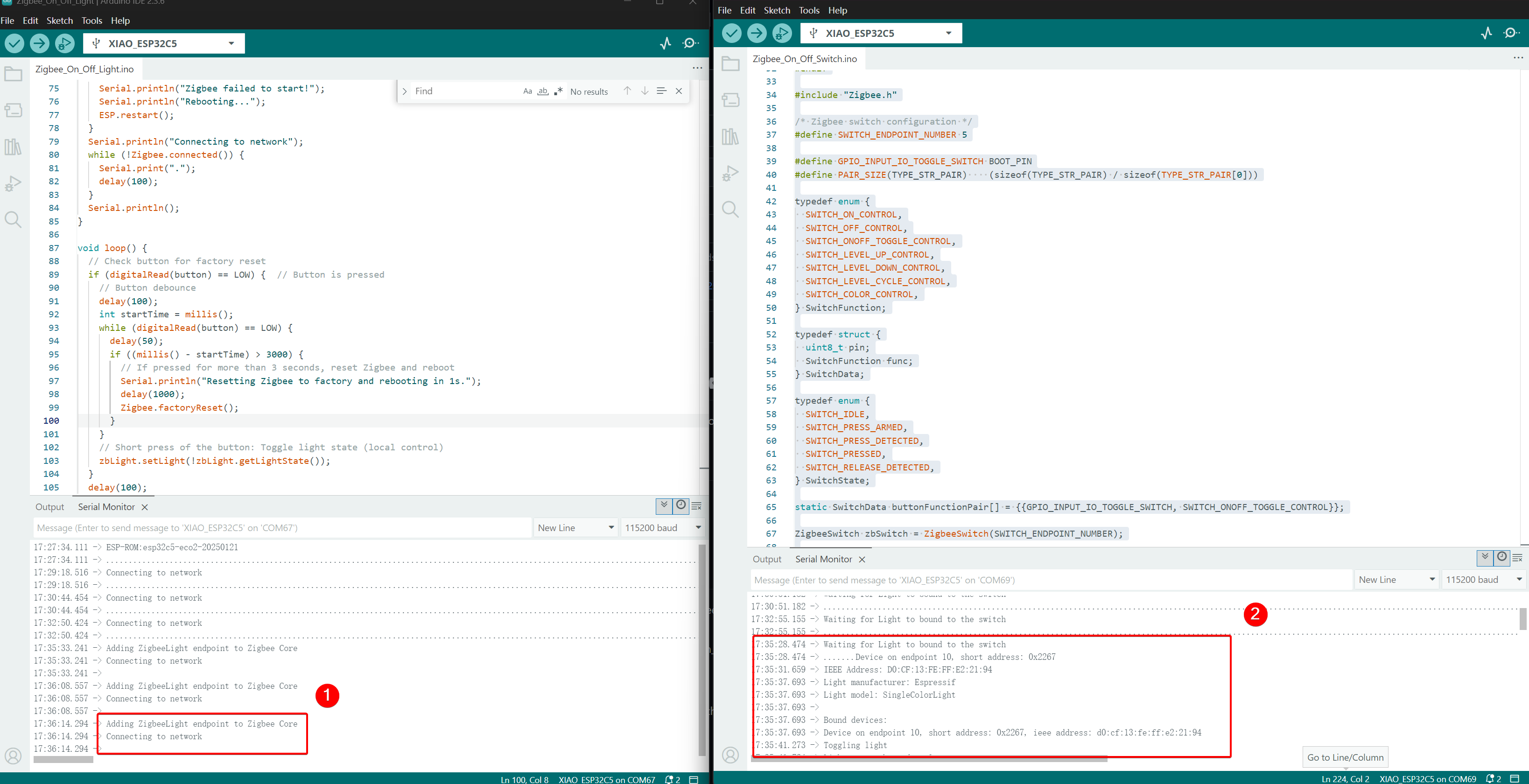
- Control Effect, when the BOOT button is pressed, the USER LED on the other XIAO ESP32-C5 will toggle.
Tech Support & Product Discussion
Thank you for choosing our products! We are here to provide you with different support to ensure that your experience with our products is as smooth as possible. We offer several communication channels to cater to different preferences and needs.