Pin Multiplexing with Seeed Studio XIAO ESP32-S3 (Sense)
| Seeed Studio XIAO ESP32-S3 | Seeed Studio XIAO ESP32-S3 Sense |
|---|---|
 |  |
The Seeed Studio XIAO ESP32-S3 is a powerful and versatile development board that features a variety of peripheral interfaces and GPIO pins. These pins can be used for various purposes, such as communicating with other devices, reading analog sensors, controlling LEDs, and more. In this tutorial, we will explore the pinout of the XIAO ESP32-S3 and its related board, the XIAO ESP32-S3 Sense, and learn how to use these pins for different purposes. Specifically, we will cover the usage of 1x UART, 1x lIC, 1x lIS, 1x SPI, 11x GPIOs (PWM), 9xADC, 1x User LED, 1x Charge LED, 1x Reset button, 1x Boot button, and, for the XIAO ESP32-S3 Sense, 1x B2B Connector (with 2 additional GPIOs). By the end of this tutorial, you will have a good understanding of the pinout of the XIAO ESP32-S3 and be able to use it effectively in your projects.
Getting Started
Pinout Overview
Before we begin, let's review all the pins that the XIAO ESP32-S3 has and its functions with the following schematic.
| XIAO ESP32-S3/XIAO ESP32-S3 Sense front indication diagram |
|---|
 |
| XIAO ESP32-S3/XIAO ESP32-S3 Sense back indication diagram |
 |
| XIAO ESP32-S3/XIAO ESP32-S3 Sense Pin List |
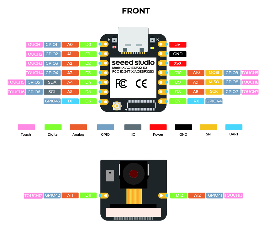 |
Although the XIAO ESP32-S3 assigns GPIO41 and GPIO42 to pins A11 and A12, due to the nature of the ESP32-S3 chip, pins A11 and A12 do not support ADC functionality. Please be sure to distinguish and differentiate between them.
-
5V - This is 5v out from the USB port. You can also use this as a voltage input but you must have some sort of diode (schottky, signal, power) between your external power source and this pin with anode to battery, cathode to 5V pin.
-
3V3 - This is the regulated output from the onboard regulator. You can draw 700mA
-
GND - Power/data/signal ground
Below is an overview of the functional pins for the XIAO ESP32-S3.
| Pin Number | Function Description |
|---|---|
| -- PDM Microphone Pins -- | |
| GPIO 41 | PDM Microphone DATA |
| GPIO 42 | PDM Microphone CLK |
| -- MicrSD Card SPI Pins -- | |
| GPIO 21 | MicroSD SPI CS |
| D8 / A8 / Qt7 / GPIO7 | MicroSD SPI SCK |
| D9 / A9 / Qt8 / GPIO8 | MicroSD SPI MISO |
| D10 / A10 / Qt9 / GPIO9 | MicroSD SPI MOSI |
| -- Camera Pins -- | |
| GPIO 10 | XMCLK |
| GPIO 11 | DVP_Y8 |
| GPIO 12 | DVP_Y7 |
| GPIO 13 | DVP_PCLK |
| GPIO 14 | DVP_Y6 |
| GPIO 15 | DVP_Y2 |
| GPIO 16 | DVP_Y5 |
| GPIO 17 | DVP_Y3 |
| GPIO 18 | DVP_Y4 |
| GPIO 38 | DVP_VSYNC |
| GPIO 39 | Camera SCL |
| GPIO 40 | Camera SDA |
| GPIO 47 | DVP_HREF |
| GPIO 48 | DVP_Y9 |
Solder header
To use the functions of each pin according to this tutorial, we recommend to solder the pins beforehand.
Due to the miniature size of XIAO ESP32-S3, please be careful when soldering headers, do not stick different pins together, and do not stick solder to the shield or other components. Otherwise, it may cause XIAO to short circuit or not work properly, and the consequences caused by this will be borne by the user.
If you have chosen the Sense version, congratulations! You will have two additional GPIO pins. If you plan to use them, you can solder a separate header onto them.
Digital
The XIAO ESP32-S3 has up to 11 regular GPIO pins and 9 analog pins. In this example, we will use the XIAO ESP32-S3, XIAO expansion board, and a relay to demonstrate how to use different digital pins for reading and writing.
Hardware Preparation
| Seeed Studio XIAO ESP32-S3 | Seeed Studio XIAO ESP32-S3 Sense | Seeed Studio Expansion Base for XIAO with Grove OLED | Grove - Relay |
|---|---|---|---|
| |  |  |
Please install XIAO ESP32-S3 or Sense onto the expansion board, and connect the relay to the A0/D0 interface of the expansion board via a Grove cable. Finally, connect XIAO to the computer via a USB-C cable.
Software Implementation
In this example, we will implement control of a relay's on/off state using a button connected to the XIAO expansion board. When the button is pressed, the relay turns on, and when the button is released, the relay turns off.
const int buttonPin = D1;     // the number of the pushbutton pin
int buttonState = 0;          // variable for reading the pushbutton status
const int relayPin = D0;

void setup() {
  // initialize the Relay pin as an output:
  pinMode(relayPin, OUTPUT);
  // initialize the pushbutton pin as an input:
  pinMode(buttonPin, INPUT_PULLUP);
}

void loop() {
  // read the state of the pushbutton value:
  buttonState = digitalRead(buttonPin);

  // check if the pushbutton is pressed. If it is, the buttonState is HIGH:
  if (buttonState == HIGH) {
    // turn Relay on:
    digitalWrite(relayPin, HIGH);
  } else {
    // turn Relay off:
    digitalWrite(relayPin, LOW);
  }
}
If everything goes smoothly, after uploading the program, you should see the following effect.
If you want to use the digital function, then you should use the letter "D" as the prefix for the pin number, such as D4, D5. Conversely, if you want to use the analog function of a pin, you should use the letter "A" as the prefix for the pin number, such as A4, A5.
For Sense Version
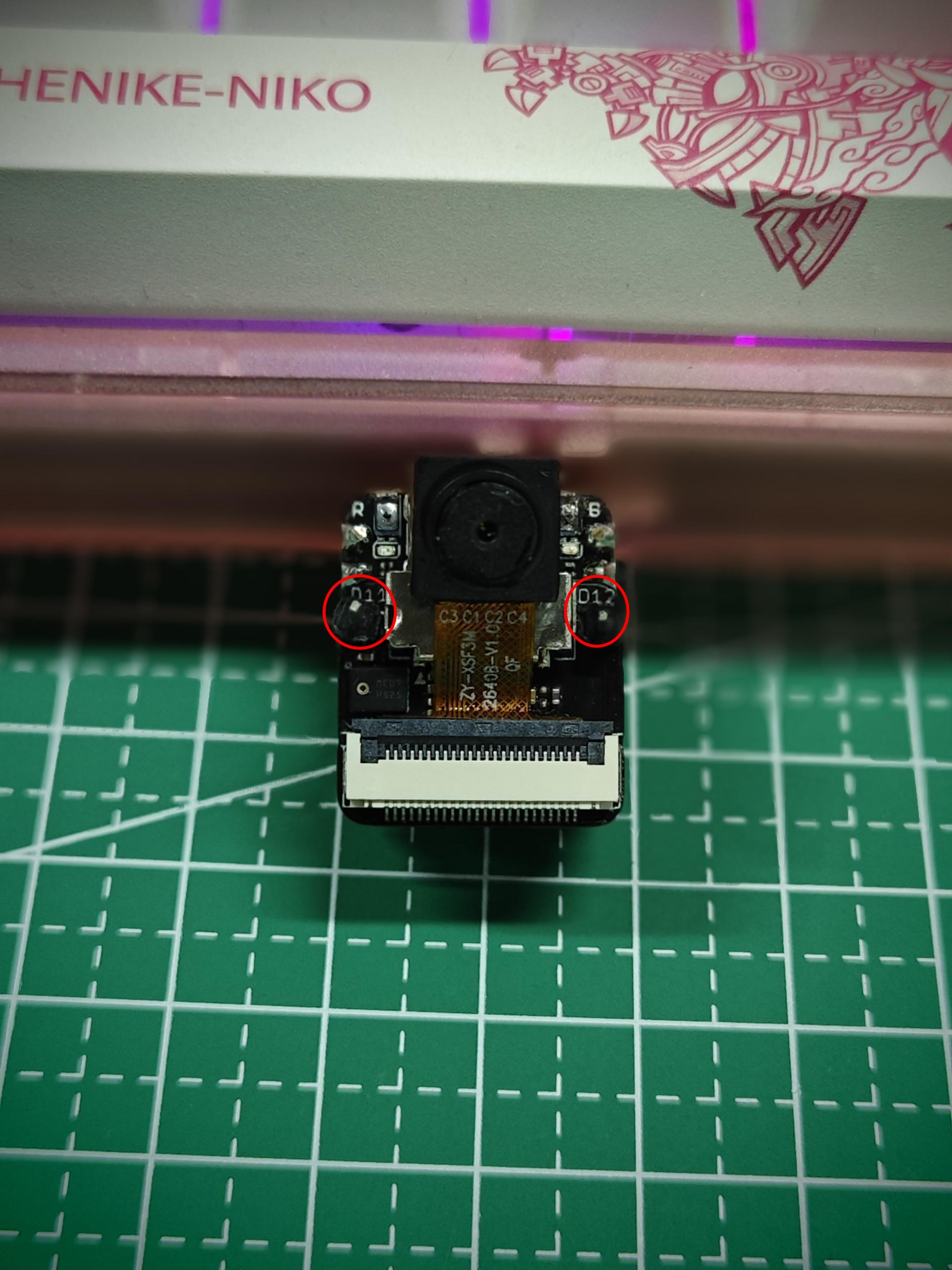
For XIAO ESP32-S3 Sense, in addition to using the 11 digital pins on XIAO, you can also use the two pins on the expansion board, which are D11 and D12. If you want to use them, please follow the steps below.
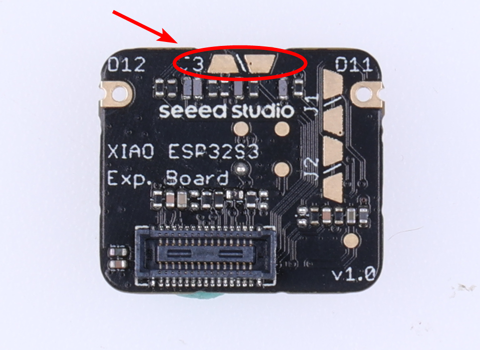
Step 1. Cut off the connection between J1 and J2
Due to the limited number of pins on the ESP32-S3, D11 and D12 on the Sense expansion board are reserved for the microphone by default. If you do need to use D11 and D12 for other purposes, you can flip over the Sense expansion board and cut the connection between J1 and J2 along the white line between the two solder pads using a sharp knife.
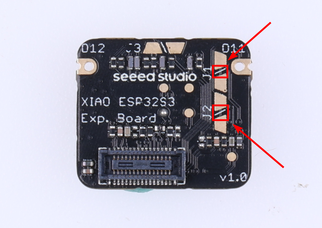
As can be seen from the picture, due to the space limitations of XIAO, many wire layouts are very compact. Therefore, when cutting the connection between J1 and J2, please be very careful not to cut outside the white line, otherwise it may cause the development board to malfunction!
Although the XIAO ESP32-S3 assigns GPIO41 and GPIO42 to pins A11 and A12, due to the nature of the ESP32-S3 chip, pins A11 and A12 do not support ADC functionality. Please be sure to distinguish and differentiate between them.
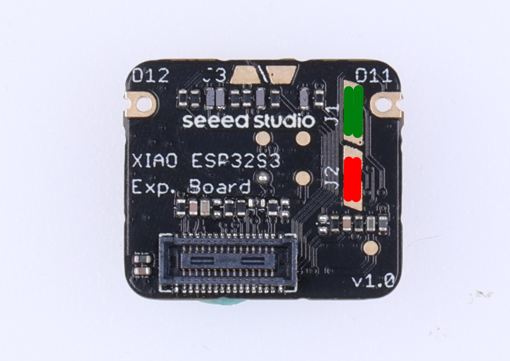
After you cut the connection between J1 and J2, the microphone function on the expansion board will no longer be available. If you need to use the microphone function, D11 and D12 pins cannot be used simultaneously. In this case, you can solder the two pads of J1 and J2 separately to restore the microphone function. As shown in the picture below, solder the red and green areas separately.
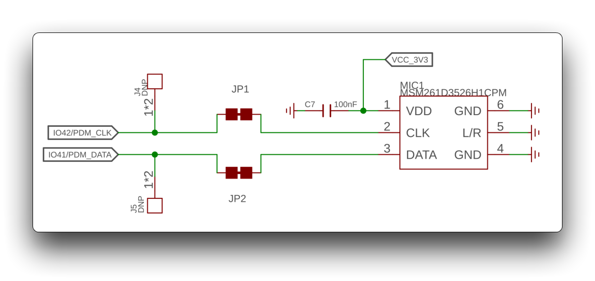
For the actual circuit schematic, please refer to the following diagram:
Step 2. Hardware preparation
| Seeed Studio XIAO ESP32-S3 Sense | Grove - Relay |
|---|---|
| |
Step 3. Software implementation
The following program toggles the relay every 500 milliseconds. Connect the SIG pin of the relay to the GPIO42 interface of the expansion board.
const int relayPin = 42;

void setup() {
  // initialize the Relay pin as an output:
  pinMode(relayPin, OUTPUT);
}

void loop() {
    // turn Relay on:
    digitalWrite(relayPin, HIGH);
    delay(500);
    // turn Relay off:
    digitalWrite(relayPin, LOW);
    delay(500);
}
The above method is also applicable to the Digital as PWM and Analog sections. You just need to modify the pin numbers of the expansion board that you want to use. This will not be repeated later.
For the two additional pins D11 and D12 on the XIAO ESP32-S3 Sense, we have not macro-defined the pins. That is, you can't use D11/A11 or D12/A12 to control these two pins yet, but you can control these two pins by using the GPIO numbers, GPIO42 and GPIO41, respectively. we will submit the macro definitions for these two pins as soon as possible, and once the submission is done, then you can D/A the pin definitions.
Digital as PWM
All GPIO pins on XIAO ESP32-S3 support PWM output. Therefore, you can use any pin to output PWM to adjust the brightness of lights, control servos, and other functions.
Hardware Preparation
| Seeed Studio XIAO ESP32-S3 | Seeed Studio XIAO ESP32-S3 Sense | Seeed Studio Expansion Base for XIAO with Grove OLED | Grove - Variable Color LED |
|---|---|---|---|
| | |  |
Please install XIAO ESP32-S3 or Sense onto the expansion board, then connect the Variable Color LED to the A0/D0 interface of the expansion board using a Grove cable. Finally, connect XIAO to your computer via USB-C cable.
Software Implementation
In this example, we will demonstrate how to use PWM output to control the brightness of a light.
int LED_pin = D0;    // LED connected to digital pin 10

void setup() {
  // declaring LED pin as output
  pinMode(LED_pin, OUTPUT);
}

void loop() {
  // fade in from min to max in increments of 5 points:
  for (int fadeValue = 0 ; fadeValue <= 255; fadeValue += 5) {
    // sets the value (range from 0 to 255):
    analogWrite(LED_pin, fadeValue);
    // wait for 30 milliseconds to see the dimming effect
    delay(30);
  }

  // fade out from max to min in increments of 5 points:
  for (int fadeValue = 255 ; fadeValue >= 0; fadeValue -= 5) {
    // sets the value (range from 0 to 255):
    analogWrite(LED_pin, fadeValue);
    // wait for 30 milliseconds to see the dimming effect
    delay(30);
  }
}
If the program runs successfully, you will see the following running effect.
Analog
On XIAO ESP32-S3, among the 11 built-in GPIO pins, except for D6 and D7 pins used for serial communication, the remaining 9 pins support Analog function. You can use these GPIO pins with analog functionality to read values from sensors that produce analog signals, such as oxygen sensors, light intensity sensors, and so on.
Although the XIAO ESP32-S3 assigns GPIO41 and GPIO42 to pins A11 and A12, due to the nature of the ESP32-S3 chip, pins A11 and A12 do not support ADC functionality. Please be sure to distinguish and differentiate between them.
Hardware Preparation
| Seeed Studio XIAO ESP32-S3 | Seeed Studio XIAO ESP32-S3 Sense | Seeed Studio Expansion Base for XIAO with Grove OLED | Grove - Oxygen Sensor |
|---|---|---|---|
| | |  |
Please install XIAO ESP32-S3 or Sense on the expansion board, then connect the Oxygen Sensor to the A0/D0 interface on the expansion board with the Grove cable. Finally, connect the XIAO to the computer via USB-C cable.
Software Implementation
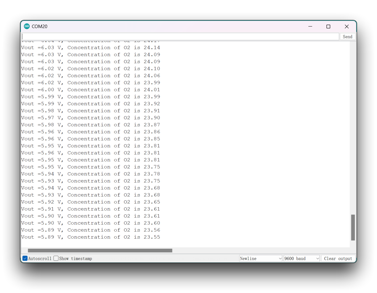
In the following program, we will use the analogRead() method to read the analog value of the sensor, and print the sensor result by using the Serial interface.
// Grove - Gas Sensor(O2) test code
// Note:
// 1. It need about about 5-10 minutes to preheat the sensor
// 2. uncomment the module name you're using
// 3. modify VRefer if needed

// comment useless one
// #define MIX8410
#define O2_W2

#ifdef MIX8410
  #define O2_COEFFICIENT 0.21
#elif defined(O2_W2)
  #define O2_COEFFICIENT 0.087
#endif

const float VRefer = 3.34;       // voltage of adc reference
const int pinAdc   = A0;

void setup()
{
    // put your setup code here, to run once:
    Serial.begin(9600);
    Serial.println("Grove - Oxygen Sensor(MIX8410) Test Code...");
}

void loop()
{
    // put your main code here, to run repeatedly:
    float Vout =0;
    Serial.print("Vout =");

    Vout = readO2Vout();
    Serial.print(Vout);
    Serial.print(" V, Concentration of O2 is ");
    Serial.println(readConcentration());
    delay(500);
}

float readO2Vout()
{
    long sum = 0;
    for(int i=0; i<32; i++)
    {
        sum += analogRead(pinAdc);
    }

    sum >>= 5;

    float MeasuredVout = sum * (VRefer / 1023.0);
    return MeasuredVout;
}

float readConcentration()
{
    // Vout samples are with reference to 3.3V
    float MeasuredVout = readO2Vout();

    //float Concentration = FmultiMap(MeasuredVout, VoutArray,O2ConArray, 6);
    //when its output voltage is 2.0V,
    float Concentration = MeasuredVout * O2_COEFFICIENT / 2.0;
    float Concentration_Percentage=Concentration*100;
    return Concentration_Percentage;
}
If you want to use the Analog function of a pin, you should use the letter "A" as the prefix for the pin number, such as A4, A5. Conversely, if you want to use the digital function, then you should use the letter "D" as the prefix for the pin number, such as D4, D5.
After uploading the program, open the Serial Monitor in Arduino IDE and set the baud rate to 9600. Wait for the oxygen sensor to warm up, and then you will be able to see the accurate oxygen concentration value.
Serial
When working with Arduino IDE, Serial communication is an essential part of many projects. To use Serial in Arduino IDE, you need to start by opening the Serial Monitor window. This can be done by clicking on the Serial Monitor icon in the toolbar or by pressing the Ctrl+Shift+M shortcut key.
General Usage
Some of the commonly used Serial functions include:
Serial.begin()-- which initializes the communication at a specified baud rate;Serial.print()-- which sends data to the Serial port in a readable format;Serial.write()-- which sends binary data to the Serial port;Serial.available()-- which checks if there is any data available to be read from the Serial port;Serial.read()-- which reads a single byte of data from the Serial port;Serial.flush()-- which waits for the transmission of outgoing serial data to complete.
By using these Serial functions, you can send and receive data between the Arduino board and your computer, which opens up many possibilities for creating interactive projects.
Here is an example program:
void setup() {
  // initialize serial communication at 9600 bits per second:
  Serial.begin(9600);
}

void loop() {
  // send data to the serial port
  Serial.println("Hello World!");

  // read data from the serial port
  if (Serial.available() > 0) {
    // read the incoming byte:
    char incomingByte = Serial.read();
    // print the incoming byte to the serial monitor:
    Serial.print("I received: ");
    Serial.println(incomingByte);
  }

  // wait for a second before repeating the loop
  delay(1000);
}
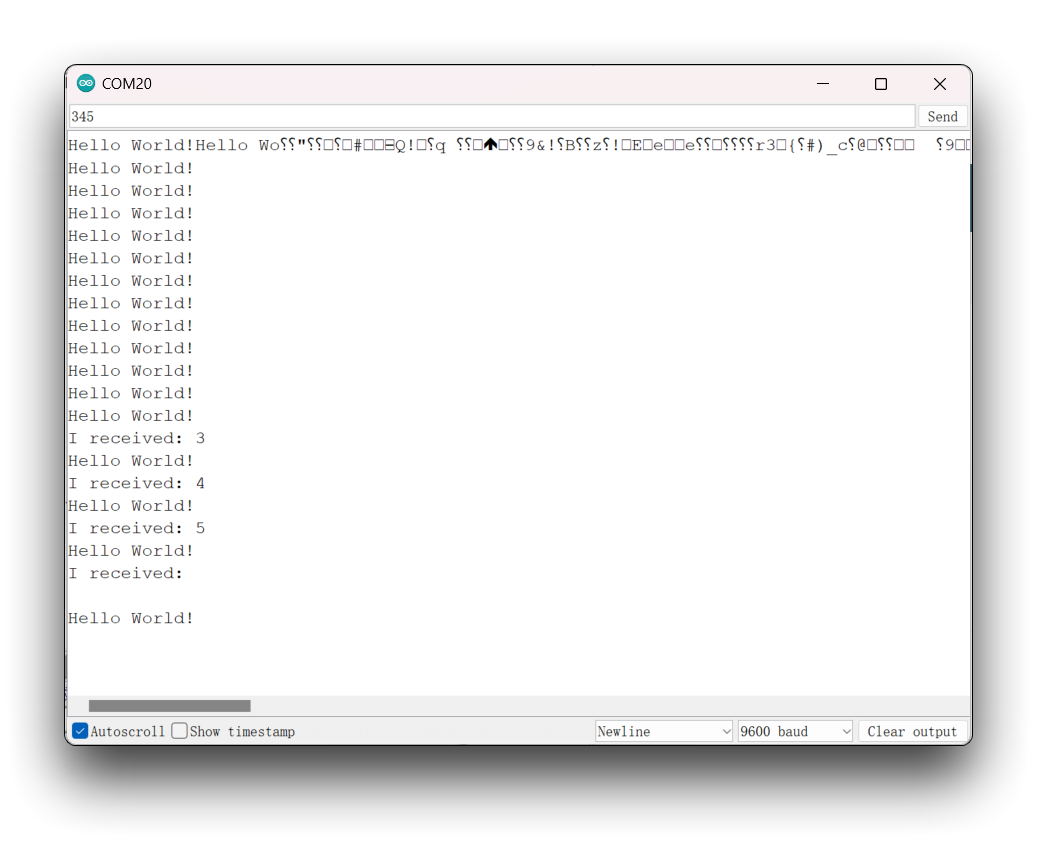
In this code, we first initialize the Serial communication at a baud rate of 9600 using the Serial.begin() function in the setup() function. Then, in the loop() function, we use the Serial.print() function to send "Hello World!" to the Serial port.
We also use the Serial.available() function to check if there is any data available to be read from the Serial port. If there is, we read the incoming byte using the Serial.read() function and store it in a variable called incomingByte. We then use the Serial.print() and Serial.println() functions to print "I received: " followed by the value of incomingByte to the Serial monitor.
Finally, we add a delay() function to wait for one second before repeating the loop. This code demonstrates how to use some of the commonly used Serial functions in Arduino IDE for sending and receiving data through the Serial port.
After uploading the program, open the Serial Monitor in Arduino IDE and set the baud rate to 9600. You will see the following message on the serial monitor, which outputs 'Hello World!' every second. Also, you can send content to the XIAO ESP32-S3 through the serial monitor, and XIAO will print out each byte of the content you send.
Serial1 Usage
According to the above XIAO ESP32-S3 Pin diagrams for specific parameters, we can observe that there are TX pin and RX pin. This is different from serial communication, but the usage is also very similar, except that a few parameters need to be added. So next, we will use the pins led out by the chip for serial communication.
Core Function that need to be include:
Serial1.begin(BAUD,SERIAL_8N1,RX_PIN,TX_PIN);-- enalbe Serial1,the function prototype :<Serial.Type>.begin(unsigned long baud, uint32_t config, int8_t rxPin, int8_t txPin);baud:baud rateconfig:Configuration bitrxPin:Receive PintxPin:Send Pin
It is worth nothing that if we use digital pin port to define,this place should be#define RX_PIN D7、#define TX_PIN D6,if we use GPIO pin port to define,this place should be #define RX_PIN 44、#define TX_PIN 43,please refer to the pin diagrams of different XIAO Series for specific parameters
Here is an example program:
#define RX_PIN D7
#define TX_PIN D6
#define BAUD 115200

void setup() {
    Serial1.begin(BAUD,SERIAL_8N1,RX_PIN,TX_PIN);
}

void loop() {
  if(Serial1.available() > 0)
  {
    char incominByte = Serial1.read();
    Serial1.print("I received : ");
    Serial1.println(incominByte);
  }
  delay(1000);
}
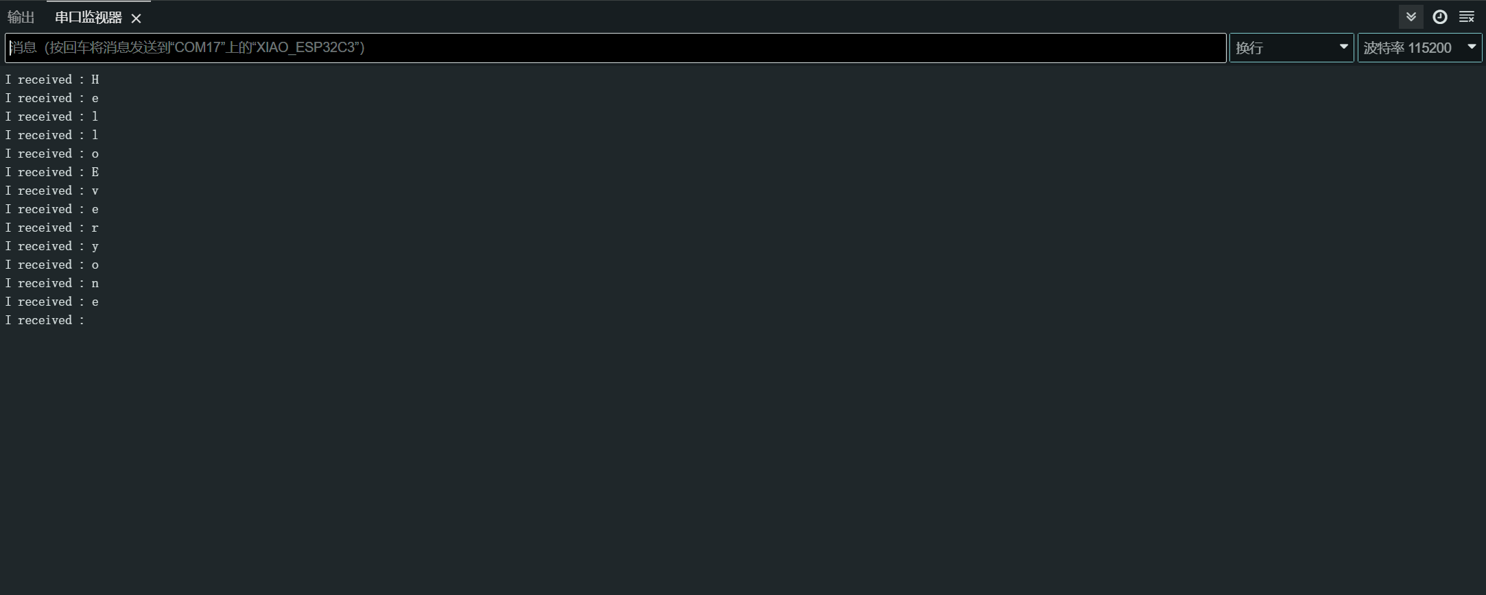
After uploading the program, open the Serial Monitor in Arduino IDE and set the baud rate to 115200.then,you can send content you want in the XIAO ESP32-S3 through the serial monitor Serial ,and XIAO will print out each byte of the content you send.,In here,the content i entered is "Hello Everyone",my result chart is as follows
Usage of Software Serial
If you feel that one hardware serial port is not enough, you can also use the ESP32's software serial function to set some pins as software serial to expand the number of serial ports.
Of course, we would recommend using the second method of mapping hardware serial ports as it is a unique feature of the ESP32. You can read more about it in the Other Hardware Serial section.
For ESP32 series chip products, if you need to use the soft serial port, you need to download the third-party soft serial port library separately. A reference is provided here.
Currently we recommend version 7.0.0 of the EspSoftwareSerial library. Other versions may have varying degrees of problems that prevent the soft serial port from working properly.
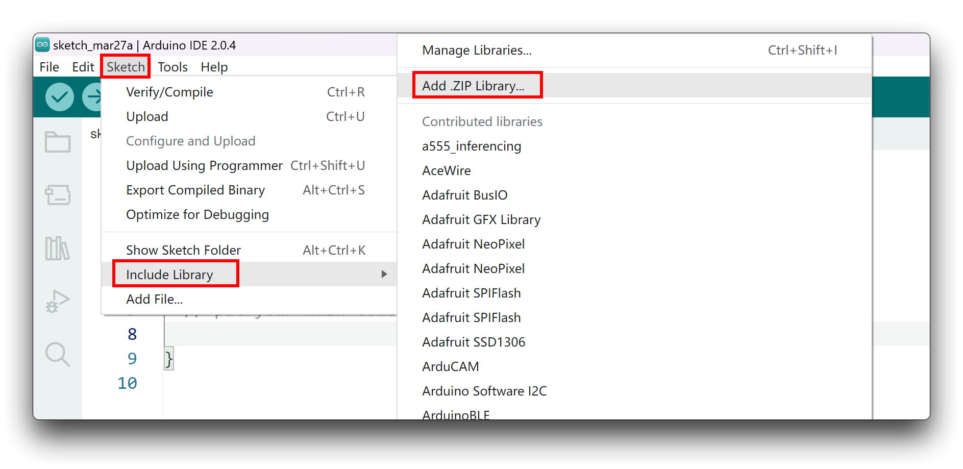
Since you have downloaded the zip Library, open your Arduino IDE, click on Sketch > Include Library > Add .ZIP Library. Choose the zip file you just downloaded,and if the library install correct, you will see Library added to your libraries in the notice window. Which means the library is installed successfully.
Then next, you can use the ESP32's soft serial port.
If you have other soft serial port libraries installed on your computer, it is likely to cause a conflict, so please check for yourself.
#include <SoftwareSerial.h>

SoftwareSerial mySerial(2, 3); // RX, TX

void setup() {
  // initialize serial communication
  Serial.begin(9600);
  while (!Serial);

  // initialize software serial
  mySerial.begin(9600);
}

void loop() {
  // read data from software serial
  if (mySerial.available()) {
    char data = mySerial.read();
    Serial.print("Received data: ");
    Serial.println(data);
  }

  // write data to software serial
  mySerial.print("Hello World!");

  // wait for a second before repeating the loop
  delay(1000);
}
In this program, we first include the SoftwareSerial.h library to use software serial. Then, we create a new SoftwareSerial object called mySerial using pins 2 and 3 as RX and TX, respectively.
In the setup() function, we initialize both the hardware serial (Serial.begin()) and the software serial (mySerial.begin()).
In the loop() function, we use the mySerial.available() function to check if there is any data available to be read from the software serial. If there is, we read the incoming byte using the mySerial.read() function and store it in a variable called data. We then use the Serial.print() and Serial.println() functions to print "Received data: " followed by the value of data to the hardware serial.
We also use the mySerial.print() function to write "Hello World!" to the software serial. This will send the data from the XIAO to the device connected to the software serial port.
Finally, we add a delay() function to wait for one second before repeating the loop.
Note that in order to use software serial on ESP32-S3, you need to select the appropriate pins for RX and TX that are not used for any other purpose. In this example, we have used pins 9 and 10 for RX and TX, respectively.
Other Hardware Serial
The ESP32S3 has a total of three UART communication interfaces, numbered from 0 to 2, which are UART0, UART1, and UART2. The pins of these three serial ports are not fixed and can be remapped to any IO port.
By default, we don't use UART0 as it is used for USB serial communication. You can use other hardware serial ports by customizing the hardware serial mapping.
// Need this for the lower level access to set them up.
#include <HardwareSerial.h>

//Define two Serial devices mapped to the two internal UARTs
HardwareSerial MySerial0(0);
HardwareSerial MySerial1(1);

void setup()
{
    // For the USB, just use Serial as normal:
    Serial.begin(115200);

    // Configure MySerial0 on pins TX=D6 and RX=D7 (-1, -1 means use the default)
    MySerial0.begin(9600, SERIAL_8N1, -1, -1);
    MySerial0.print("MySerial0");

    // And configure MySerial1 on pins RX=D9, TX=D10
    MySerial1.begin(115200, SERIAL_8N1, D9, D10);
    MySerial1.print("MySerial1");
}

void loop()
{

}
In the following, we will take the 60GHz mmWave Sensor - Human Resting Breathing and Heartbeat Module, which is available for sale, as an example, and explain how to use the D9 and D10 hardware serial ports and the USB serial port.
Please be prepared for the following.
| Seeed Studio XIAO ESP32-S3 | Seeed Studio XIAO ESP32-S3 Sense | 60GHz mmWave Sensor - Human Resting Breathing and Heartbeat Module |
|---|---|---|
| | 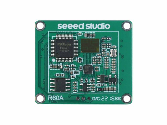 |
Download the sensor library to your computer. And add it to the Arduino IDE.
Here, we want to parse the heartbeat and respiration data information, then you can rewrite your program like this.
#include "Arduino.h"
#include <60ghzbreathheart.h>
#include <HardwareSerial.h>

HardwareSerial MySerial(0);   //Create a new HardwareSerial class -- D6/D7

// can also try hardware serial with
BreathHeart_60GHz radar = BreathHeart_60GHz(&MySerial);

void setup() {
  // put your setup code here, to run once:
  Serial.begin(115200);
  MySerial.begin(115200, SERIAL_8N1, 9, 10); // at CPU Freq is 40MHz, work half speed of defined.

  while(!Serial);   //When the serial port is opened, the program starts to execute.

  Serial.println("Readly");

  // radar.ModeSelect_fuc(1);  //1: indicates real-time transmission mode, 2: indicates sleep state mode.
  //After setting the mode, if you do not see data returned, you may need to re-power the sensor.
}

void loop()
{
  // put your main code here, to run repeatedly:
  radar.Breath_Heart();           //Breath and heartbeat information output
  if(radar.sensor_report != 0x00){
    switch(radar.sensor_report){
      case HEARTRATEVAL:
        Serial.print("Sensor monitored the current heart rate value is: ");
        Serial.println(radar.heart_rate, DEC);
        Serial.println("----------------------------");
        break;
      case HEARTRATEWAVE:  //Valid only when real-time data transfer mode is on
        Serial.print("The heart rate waveform(Sine wave) -- point 1: ");
        Serial.print(radar.heart_point_1);
        Serial.print(", point 2 : ");
        Serial.print(radar.heart_point_2);
        Serial.print(", point 3 : ");
        Serial.print(radar.heart_point_3);
        Serial.print(", point 4 : ");
        Serial.print(radar.heart_point_4);
        Serial.print(", point 5 : ");
        Serial.println(radar.heart_point_5);
        Serial.println("----------------------------");
        break;
      case BREATHNOR:
        Serial.println("Sensor detects current breath rate is normal.");
        Serial.println("----------------------------");
        break;
      case BREATHRAPID:
        Serial.println("Sensor detects current breath rate is too fast.");
        Serial.println("----------------------------");
        break;
      case BREATHSLOW:
        Serial.println("Sensor detects current breath rate is too slow.");
        Serial.println("----------------------------");
        break;
      case BREATHNONE:
        Serial.println("There is no breathing information yet, please wait...");
        Serial.println("----------------------------");
        break;
      case BREATHVAL:
        Serial.print("Sensor monitored the current breath rate value is: ");
        Serial.println(radar.breath_rate, DEC);
        Serial.println("----------------------------");
        break;
      case BREATHWAVE:  //Valid only when real-time data transfer mode is on
        Serial.print("The breath rate waveform(Sine wave) -- point 1: ");
        Serial.print(radar.breath_point_1);
        Serial.print(", point 2 : ");
        Serial.print(radar.breath_point_2);
        Serial.print(", point 3 : ");
        Serial.print(radar.breath_point_3);
        Serial.print(", point 4 : ");
        Serial.print(radar.breath_point_4);
        Serial.print(", point 5 : ");
        Serial.println(radar.breath_point_5);
        Serial.println("----------------------------");
        break;
    }
  }
  delay(200);                       //Add time delay to avoid program jam
}
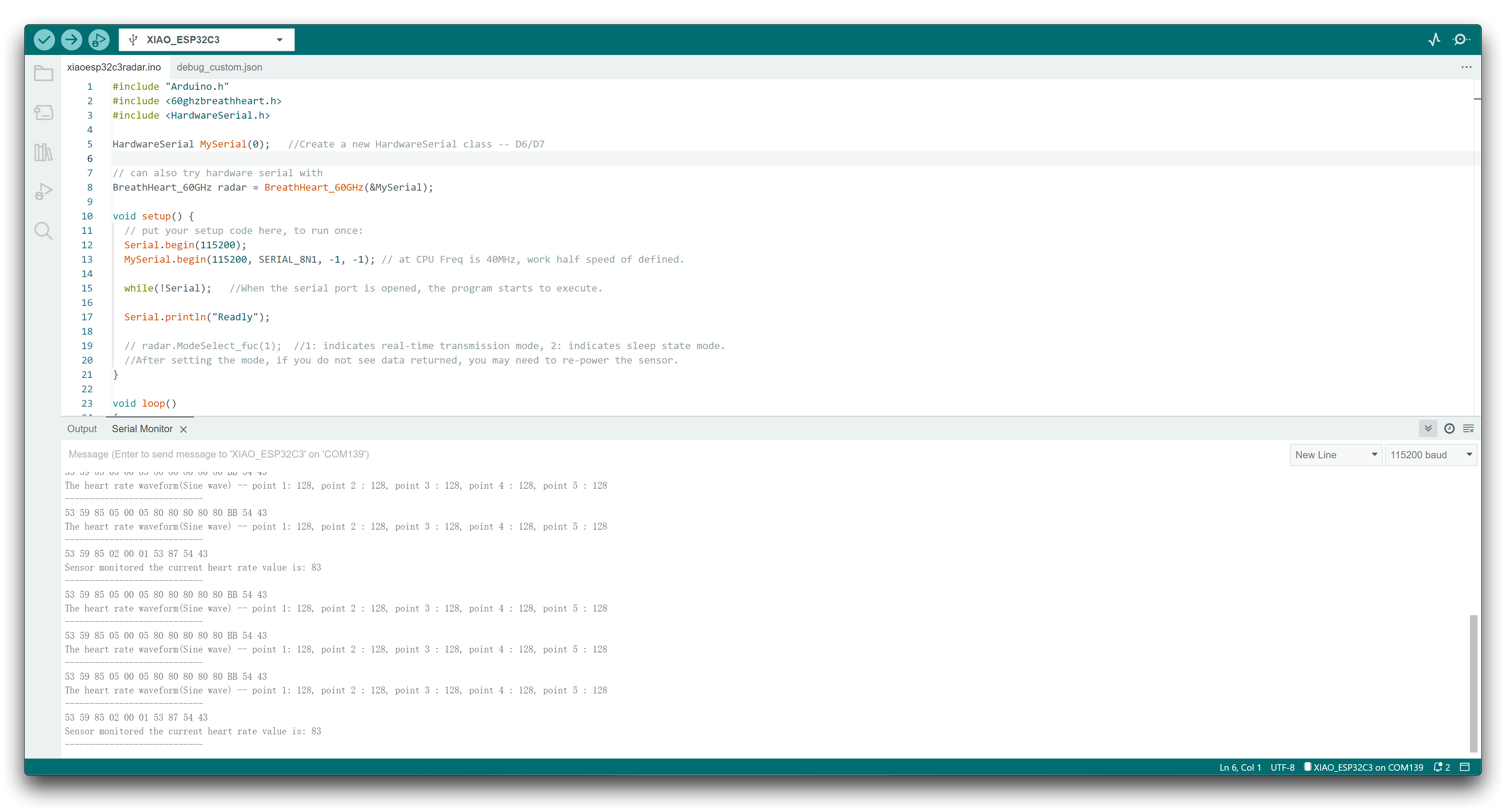
Please upload the program, then open the serial monitor and set the baud rate to 115200.
If all goes well, you will see data messages on the serial monitor.
IIC
XIAO ESP32-S3 has an I2C interface that can be used for data transmission and parsing of many sensors, as well as for using some OLED screens.
Hardware Preparation
| Seeed Studio XIAO ESP32-S3 | Seeed Studio XIAO ESP32-S3 Sense | Seeed Studio Expansion Base for XIAO with Grove OLED |
|---|---|---|
| | |
The OLED display on the XIAO expansion board uses the I2C protocol and is connected to the XIAO's I2C interface through the I2C circuit on the board. Therefore, we can directly plug the XIAO into the expansion board and program it to display content on the screen.
Software Implementation
This example introduces how to use the OLED display on the Seeed Studio Expansion Base for XIAO ESP32-S3.
Step 1. Install the Seeed Studio XIAO ESP32-S3 on the Expansion board then conect the Type-C cable
Step 2. Install the u8g2 library
Step 3. Copy the code and stick on the Ardiono IDE then upload it
#include <Arduino.h>
#include <U8x8lib.h>
#include <Wire.h>

U8X8_SSD1306_128X64_NONAME_HW_I2C u8x8(/* clock=*/ SCL, /* data=*/ SDA, /* reset=*/ U8X8_PIN_NONE);   // OLEDs without Reset of the Display

void setup(void) {
  u8x8.begin();
  u8x8.setFlipMode(1);   // set number from 1 to 3, the screen word will rotary 180
}

void loop(void) {
  u8x8.setFont(u8x8_font_chroma48medium8_r);
  u8x8.setCursor(0, 0);
  u8x8.print("Hello World!");
}
In the first few lines of the code, we include the required libraries such as Arduino.h, U8x8lib.h, and Wire.h. The U8x8lib.h library provides functions to control the OLED display, and the Wire.h library provides functions for I2C communication.
In the setup() function, we initialize the OLED display using the u8x8.begin() function. We also set the flip mode of the display using the u8x8.setFlipMode() function to rotate the screen 180 degrees.
In the loop() function, we set the font using the u8x8.setFont() function and specify the position of the cursor on the display using the u8x8.setCursor() function. Finally, we use the u8x8.print() function to display the string "Hello World!" on the OLED display.
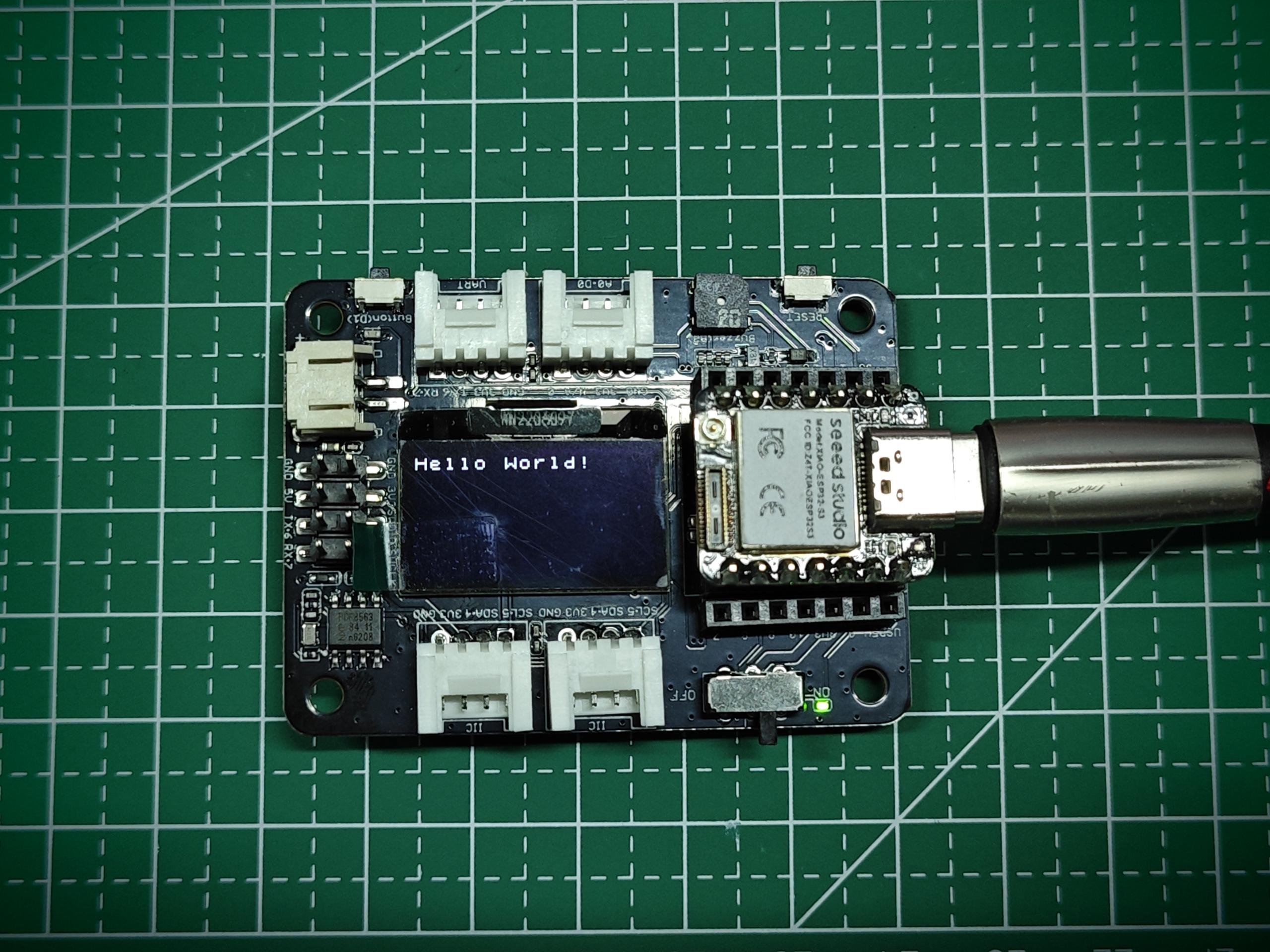
If you upload a program to XIAO ESP32-S3, you will see content displayed on the OLED display screen on the expansion board.
SPI
The ESP32-S3 chip integrates multiple peripherals, including an SPI interface that can be used to connect external SPI devices such as flash memory, displays, sensors, and more. The ESP32-S3 also supports high-speed SPI transfer mode, which can achieve a maximum SPI transfer rate of 80 MHz, meeting the data transfer needs of most SPI devices.
Hardware Preparation
| Seeed Studio XIAO ESP32-S3 | Seeed Studio XIAO ESP32-S3 Sense | Grove - OLED Display 1.12 (SH1107) V3.0 - SPI/IIC |
|---|---|---|
| | _V3.0/img/10402050_Main-02.png) |
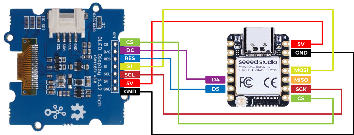
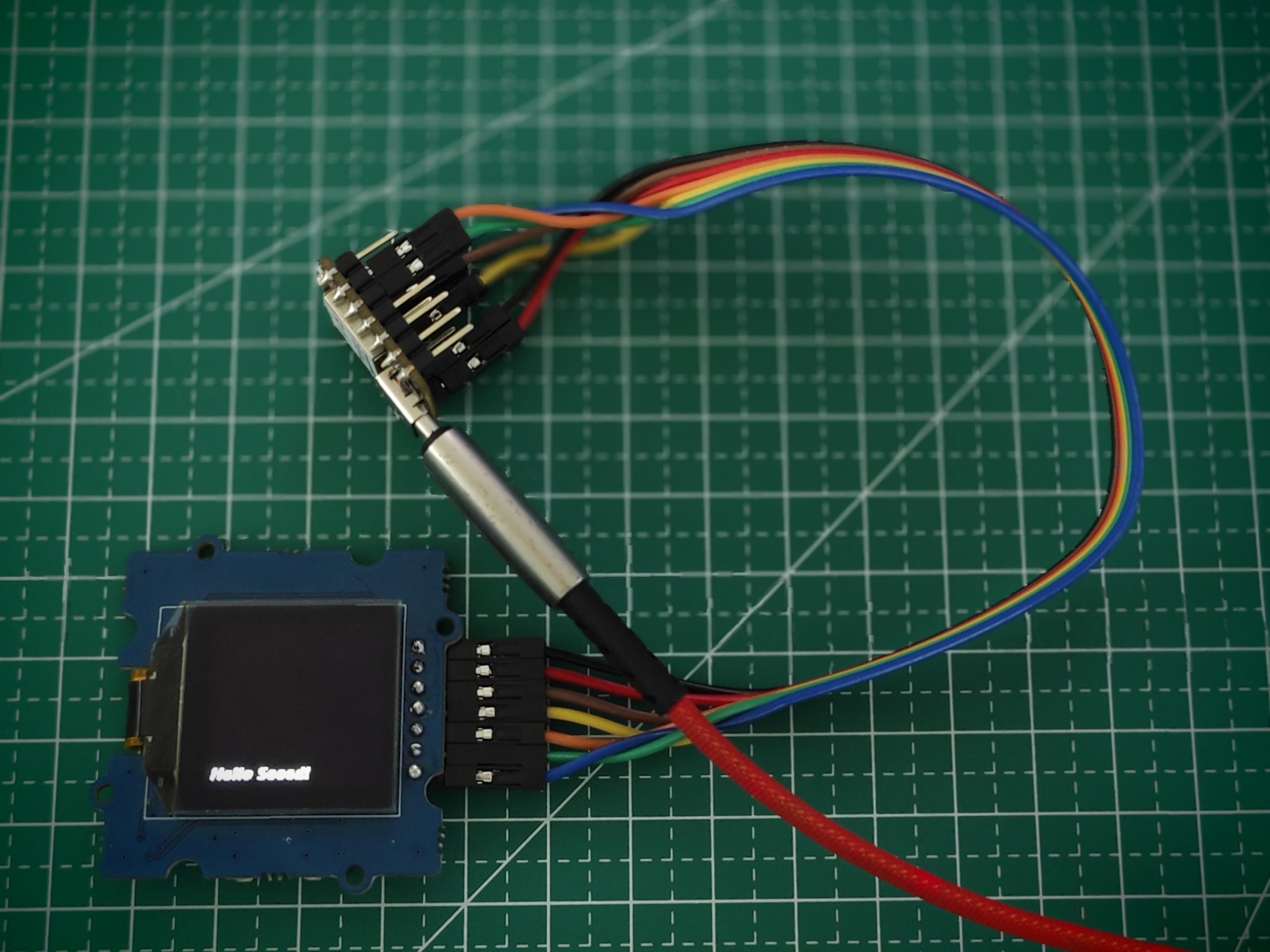
After preparing the hardware as mentioned above, use jumper wires to connect the SPI interface of the XIAO and OLED. Please refer to the following diagram for the wiring method.
Software Implementation
Next, we will take the following program as an example to introduce how to use the SPI interface to control the OLED screen display.
Install the u8g2 library.
#include <Arduino.h>
#include <U8g2lib.h>
#include <SPI.h>
#include <Wire.h>

U8G2_SH1107_128X128_1_4W_HW_SPI u8g2(U8G2_R3, /* cs=*/ D7, /* dc=*/ D4, /* reset=*/ D5);

void setup(void) {
  u8g2.begin();
}

void loop(void) {
  u8g2.firstPage();

  do {
    u8g2.setFont(u8g2_font_luBIS08_tf);
    u8g2.drawStr(0,24,"Hello Seeed!");
  } while ( u8g2.nextPage() );
}
In the setup() function, the U8G2_SH1107_128X128_1_4W_HW_SPI class is instantiated with the appropriate constructor arguments that specify the pins used for chip select (cs), data/command (dc), and reset. Then, the u8g2.begin() function is called to initialize the display.
In the loop() function, the display is updated with new content using the u8g2.firstPage(), u8g2.setFont(), and u8g2.drawStr() functions. The u8g2.firstPage() function sets up the display buffer for writing, while u8g2.nextPage() displays the updated content. The do-while loop ensures that the content is displayed continuously until the program is stopped.
Overall, this code demonstrates how to use the U8g2 library to control an OLED display and display text on it.
For Sense
If you purchased the Sense version and need to connect to the expansion board, please note that the SD card on the expansion board will occupy the SPI pins, which may result in the SPI pins being unavailable.
The solder pad interfaces provided on the Sense expansion board allow users to select the required functions. Among them, the function of the J3 solder pad is to enable the SPI or SD card functionality.
| If you want to use the SPI Pins / Disable the SD card of the expansion board | If you want to enable the SD card on the expansion board / Disable the SPI Pins |
|---|---|
 |  |
| Cut along the white thin line to disconnect the solder pad connection. | Solder the two solder pads together. |
As can be seen from the picture, due to the space limitations of XIAO, many wire layouts are very compact. Therefore, when cutting the connection of J3, please be very careful not to cut outside the white line, otherwise it may cause the development board to malfunction!
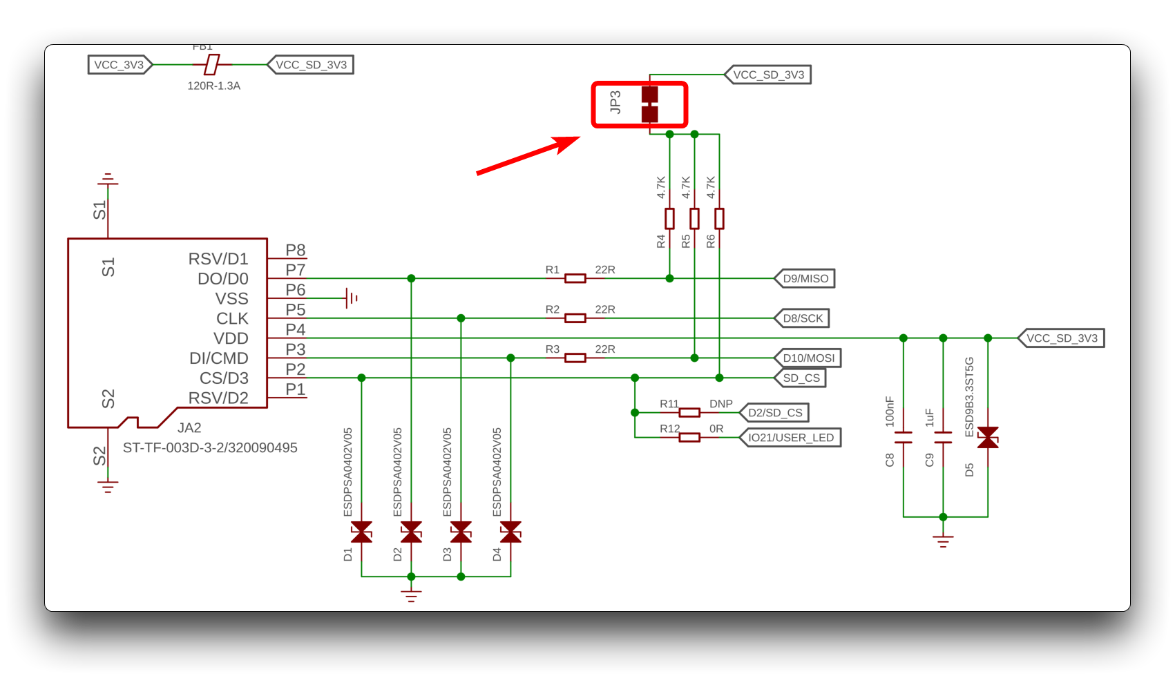
For the sake of common sense, the J3 is simply described above as an interface that turns the SD card function on or off, but this is actually inaccurate. The actual circuit connection is shown below. Cutting off J3 actually disconnects the pull-up resistors from R4 to R6, which is the main reason why the SD card function is disabled while the SPI function is restored to normal.
Touch Pins
In addition to the common functional pins mentioned above, XIAO ESP32-S3/XIAO ESP32-S3 Sense also has 9 touch detection pins A0A5, A8A10.
We can check if a pin has been touched by reading its analog value, which is very convenient. The following program is used to detect whether pin A5 has been touched.
const int touch_pin = A5;

void setup(void) {
  Serial.begin(9600);
}

void loop(void) {
  Serial.print("Touch value: ");
  Serial.println(analogRead(touch_pin));
  delay(1000);
}
After uploading the program, open the serial monitor and set the baud rate to 9600. Then touch pin A5, and you will find that the analog reading value will be significantly larger than the value before touching.
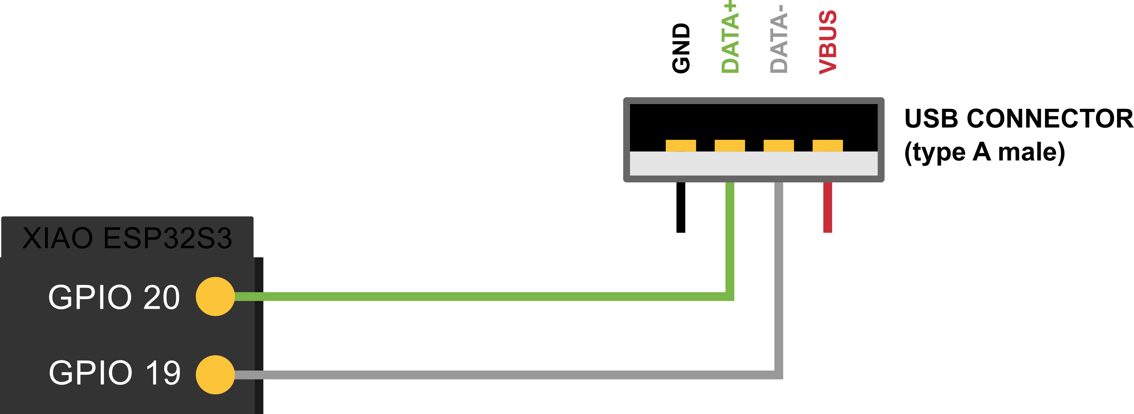
USB Pins
ESP32-S3 is a microcontroller that integrates Wi-Fi and Bluetooth functionalities, and its D+ and D- pins are used to support USB communication. Specifically, these two pins are differential signal lines used for high-speed data transmission between USB 2.0 devices and hosts.
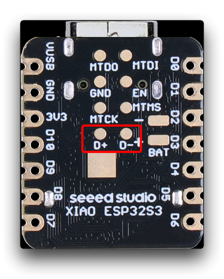
The D+ pin is the positive polarity line used for sending data, while the D- pin is the negative polarity line used for sending data. When a USB device is connected to a host, the host detects voltage changes on these two pins to determine the device's connection status and transmission speed. During data transmission, the D+ and D- pins alternately transmit data bits and synchronization signals to achieve reliable data transmission.
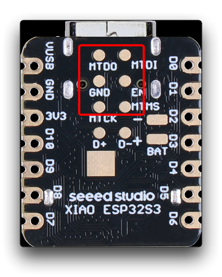
JTAG Pins
The JTAG (Joint Test Action Group) interface of ESP32-S3 is a debugging and testing interface that can be used for very low-level hardware debugging and programming during development, debugging, and testing. The JTAG interface includes a set of standard signal lines, including clock lines, data input lines, data output lines, test mode select lines, test mode clock lines, and so on.
The JTAG interface of ESP32-S3 can be used for the following purposes:
-
Debugging: The JTAG interface can be used for debugging and single-step execution in the ESP32-S3 chip to help developers find and resolve code errors.
-
Flashing programs: Through the JTAG interface, programs or debugging firmware can be loaded into the ESP32-S3 chip.
-
Reading CPU state: The JTAG interface can be used to read the CPU state, memory content, and register values of the ESP32-S3 chip for debugging and testing.
It should be noted that using the JTAG interface requires dedicated hardware devices and software tools, as well as corresponding professional knowledge and skills. Therefore, in general, the JTAG interface is only used in specific scenarios such as development, debugging, and testing. For general users, using other functions and interfaces of ESP32-S3 is already sufficient.
If you want to know more about JTAG Debugging, please read the official ESP32 documentation.
Troubleshooting
Q1: Why am I getting the following error when using the serial monitor?
A: If you encounter this type of error, please turn on the USB CDC On Boot switch.
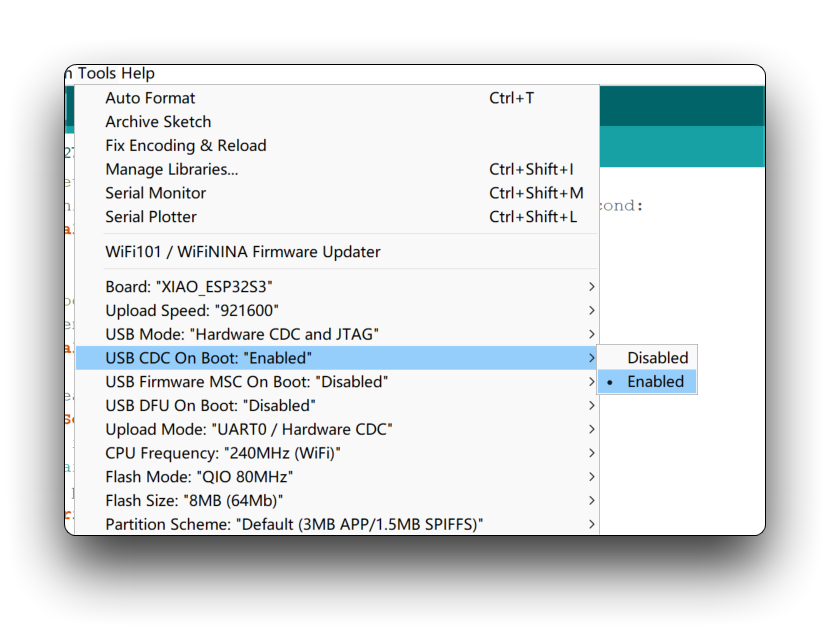
This issue may also manifest as an empty serial output in Arduino IDE 2.x, and it may also be caused by this same reason.
Q2: What features does the ESP-32 support or not support?
A: The following is a list of supported/unsupported features provided by ESP32. As of April 10, 2023.
| Peripheral | ESP32 | ESP32-S2 | ESP32-C3 | ESP32-S3 | Comments |
|---|---|---|---|---|---|
| ADC | Yes | Yes | Yes | Yes | |
| Bluetooth | Yes | Not Supported | Not Supported | Not Supported | Bluetooth Classic |
| BLE | Yes | Not Supported | Yes | Yes | |
| DAC | Yes | Yes | Not Supported | Not Supported | |
| Ethernet | Yes | Not Supported | Not Supported | Not Supported | (*) |
| GPIO | Yes | Yes | Yes | Yes | |
| Hall Sensor | Yes | Not Supported | Not Supported | Not Supported | |
| I2C | Yes | Yes | Yes | Yes | |
| I2S | Yes | Yes | Yes | Yes | |
| LEDC | Yes | Yes | Yes | Yes | |
| Motor PWM | No | Not Supported | Not Supported | Not Supported | |
| Pulse Counter | No | No | No | No | |
| RMT | Yes | Yes | Yes | Yes | |
| SDIO | No | No | No | No | |
| SDMMC | Yes | Not Supported | Not Supported | Yes | |
| Timer | Yes | Yes | Yes | Yes | |
| Temp. Sensor | Not Supported | Yes | Yes | Yes | |
| Touch | Yes | Yes | Not Supported | Yes | |
| TWAI | No | No | No | No | |
| UART | Yes | Yes | Yes | Yes | |
| USB | Not Supported | Yes | Yes | Yes | ESP32-C3 only CDC/JTAG |
| Wi-Fi | Yes | Yes | Yes | Yes |
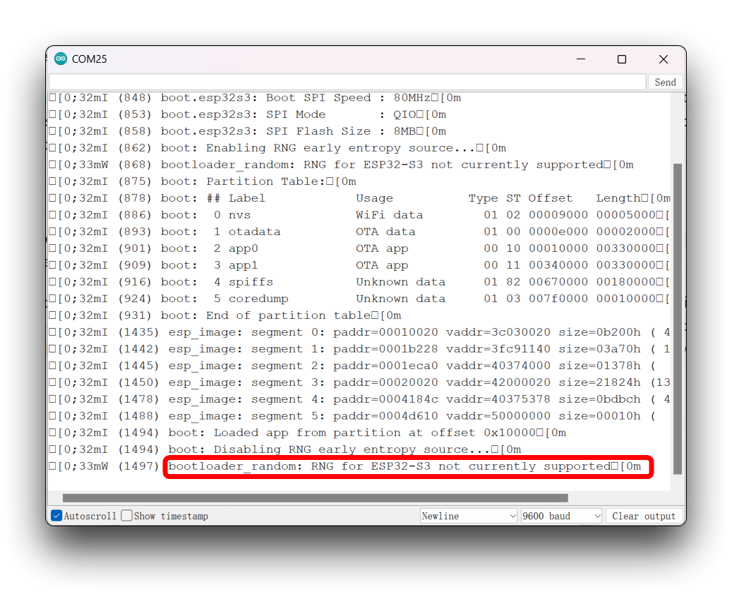
Q3: Why can I always see the debug message of the chip in the serial monitor?
A: You can try to turn off the output of debug messages using the following method, Tool -> Core Debug Level: -> None in the Arduino IDE.
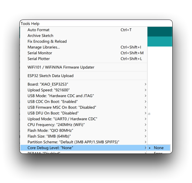
However, this method does not always work, in fact, the debug information of ESP32-S3 is always printed from the serial port, which cannot be changed. Please forgive it, it's just too eager to let you know it's working properly.
Q4: Why I cut the connection of J3, but still test to get D8 and D9 pins high? The write to microSD card still has a probability of success?
In terms of SD card design, the correct circuit must have pull-up resistors to make the microSD card work properly. If you find that the pin level and card reading and writing are still normal after cutting J3, this may just be a lucky situation and we do not recommend you to read and write the card in this case, which may cause the problem of losing the written data. While D8 and D9 pins can be modified level by writing low level after cutting J3.
Tech Support & Product Discussion
Thank you for choosing our products! We are here to provide you with different support to ensure that your experience with our products is as smooth as possible. We offer several communication channels to cater to different preferences and needs.