Usage of Seeed Studio XIAO MG24 Sense built-in Sensor
XIAO MG24 Sense IMU
Overview of Built-in Sensors
6-Axis IMU (Inertial Measurement Unit) Sensors like the LSM6DS3TR-C integrate accelerometers and gyroscopes to measure the motion and orientation of an object in three-dimensional space. Specifically, the LSM6DS3TR-C has the following features:
Accelerometer function:
- Measures the acceleration of an object along the X, Y, and Z axes. It is able to sense object motion (e.g., rest, acceleration, deceleration) and tilt changes (e.g., angle of the object).
- It can be used to detect gait, position changes, vibrations, etc.
Gyroscope function (Gyroscope):
- Measures the angular velocity of an object around the X, Y, and Z axes, i.e., the rotation of the object.
- Can be used to detect rotation, rate of rotation, and change in direction.
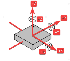
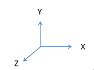
- The X-axis angle ( Roll ) is the angle in the direction of rotation around the X-axis.
- The Y-axis angle ( Pitch ) is the angle in the direction of rotation around the Y-axis.
- The Z-axis angle ( Yaw ) is the angle in the direction of rotation around the Z-axis.
Software Preparation
Click on the github download link to drive the six-axis sensor.
Code Implementation
#include <LSM6DS3.h>
#include <Wire.h>

//Create a instance of class LSM6DS3
LSM6DS3 myIMU(I2C_MODE, 0x6A);    //I2C device address 0x6A
float aX, aY, aZ, gX, gY, gZ;
const float accelerationThreshold = 2.5; // threshold of significant in G's
const int numSamples = 119;
int samplesRead = numSamples;

void setup() {
  // put your setup code here, to run once:
  Serial.begin(9600);
  while (!Serial);

  pinMode(PD5,OUTPUT);
  digitalWrite(PD5,HIGH);
  //Call .begin() to configure the IMUs
  if (myIMU.begin() != 0) {
    Serial.println("Device error");
  } else {
    Serial.println("aX,aY,aZ,gX,gY,gZ");
  }
}

void loop() {
  // wait for significant motion
  while (samplesRead == numSamples) {
    // read the acceleration data
    aX = myIMU.readFloatAccelX();
    aY = myIMU.readFloatAccelY();
    aZ = myIMU.readFloatAccelZ();

    // sum up the absolutes
    float aSum = fabs(aX) + fabs(aY) + fabs(aZ);

    // check if it's above the threshold
    if (aSum >= accelerationThreshold) {
      // reset the sample read count
      samplesRead = 0;
      break;
    }
  }

  // check if the all the required samples have been read since
  // the last time the significant motion was detected
  while (samplesRead < numSamples) {
    // check if both new acceleration and gyroscope data is
    // available
    // read the acceleration and gyroscope data

    samplesRead++;

    // print the data in CSV format
    Serial.print(myIMU.readFloatAccelX(), 3);
    Serial.print(',');
    Serial.print(myIMU.readFloatAccelY(), 3);
    Serial.print(',');
    Serial.print(myIMU.readFloatAccelZ(), 3);
    Serial.print(',');
    Serial.print(myIMU.readFloatGyroX(), 3);
    Serial.print(',');
    Serial.print(myIMU.readFloatGyroY(), 3);
    Serial.print(',');
    Serial.print(myIMU.readFloatGyroZ(), 3);
    Serial.println();

    if (samplesRead == numSamples) {
      // add an empty line if it's the last sample
      Serial.println();
    }
  }
}
Due to the update of the LSM6DS3 library, if you have previously added this library to the user, you will need to re-download version 2.0.4 or higher and add the ZIP file to the Arduino.
Function Overview
-
Include Libraries
  #include <LSM6DS3.h>
#include <Wire.h>- Includes the library for communicating with the LSM6DS3 sensor.
- Includes the library for I2C communication.
-
Create Sensor Instance
LSM6DS3 myIMU(I2C_MODE, 0x6A)Creates an instance of the LSM6DS3 class for the IMU sensor, specifying I2C communication mode and the device address 0x6A.
-
Variables and Constants
float aX, aY, aZ, gX, gY, gZ: Variables to store accelerometer and gyroscope data.const float accelerationThreshold = 2.5: The threshold value in G's for detecting significant motion.const int numSamples = 119: The number of samples to collect after detecting significant motion.int samplesRead = numSamples: Initializes the sample counter to the total number of samples, indicating no data has been collected yet.
-
Basic Settings
  pinMode(PD5,OUTPUT);
digitalWrite(PD5,HIGH);- Turn on the gyro enable pin.
-
Data Processing
aX = myIMU.readFloatAccelX();:
aY = myIMU.readFloatAccelY();:
aZ = myIMU.readFloatAccelZ();:
float aSum = fabs(aX) + fabs(aY) + fabs(aZ);- Reads the acceleration along X.
- Reads the acceleration along Y.
- Reads the acceleration along Z.
- Calculate the sum of the absolute values of the acceleration data,
fabs()Returns the absolute value.
  // check if it's above the threshold
  if (aSum >= accelerationThreshold) {
    // reset the sample read count
    samplesRead = 0;
    break;
}- If the sum of the absolute acceleration values is greater than or equal to the set threshold, reset the sample count samplesRead to 0 and exit the loop.
-
Check Data
while (samplesRead < numSamples) {
  samplesRead++;
  .
  .
  .
  .
  .
  if (samplesRead == numSamples) {
    // add an empty line if it's the last sample
    Serial.println();
  }
}- Go to another loop and check if the required number of samples have been read.
- Increase the count of samplesRead.
- If all samples have been read, print a blank line to separate the data output.
Results Chart
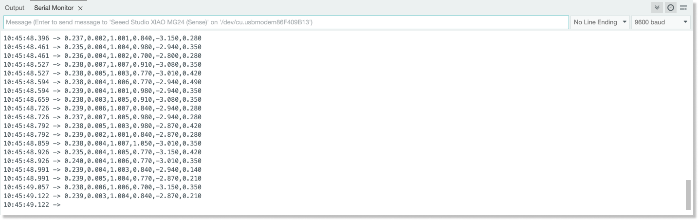
Greater
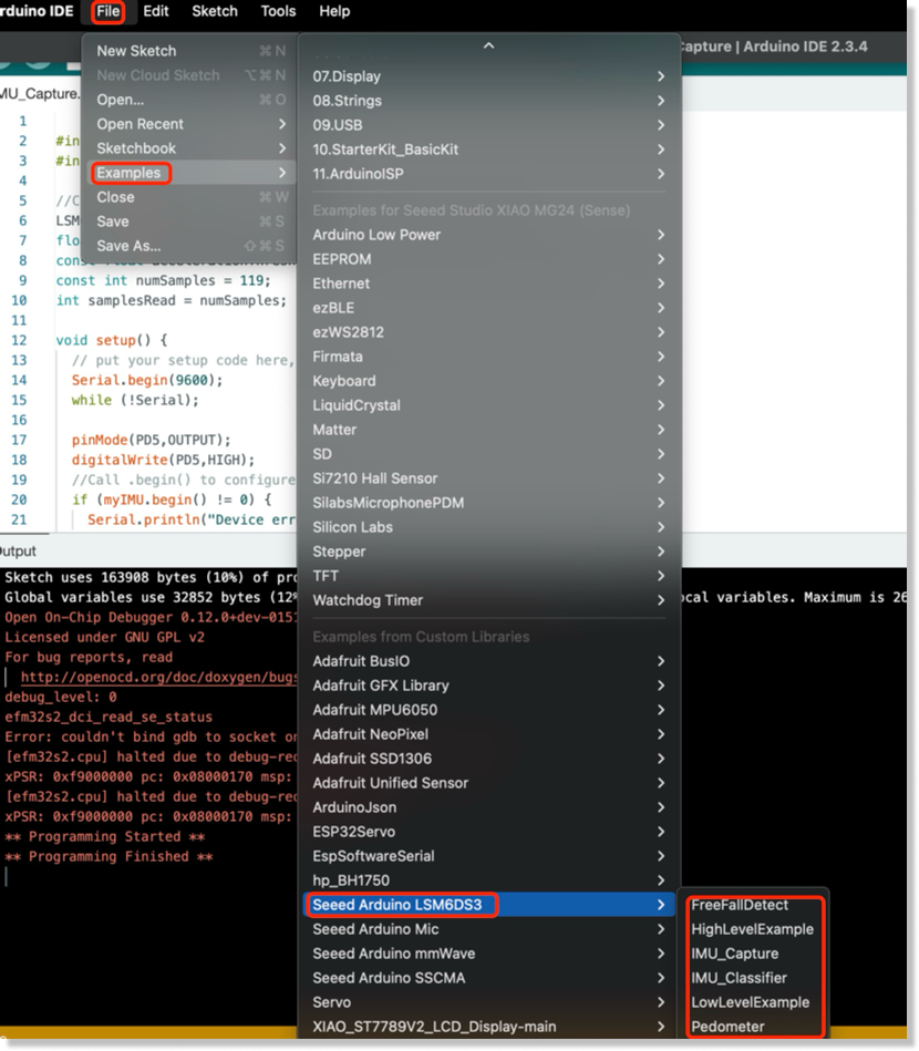
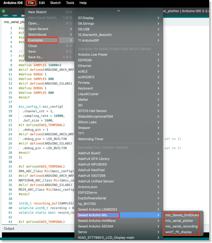
If you want more sample code , Please Click : "File" -> Example -> Seeed Arduino LSM6DS3"
IMU Advanced Demo
Hadware Preparation
| Seeeduino-XIAO-Expansion-Board | Seeed Studio XIAO MG24 Sense |
|---|---|
 |  |
Software Preparation
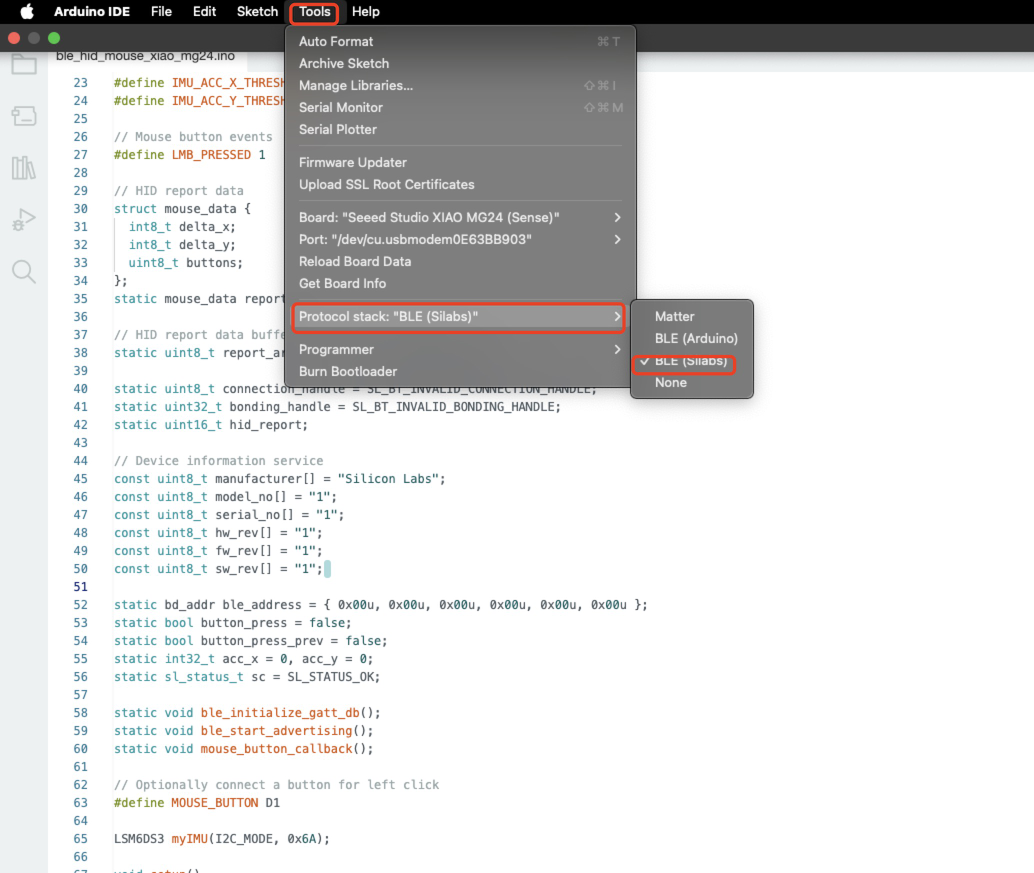
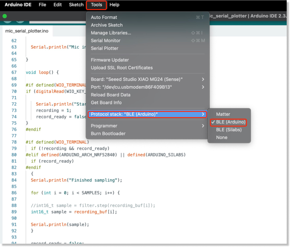
We need to select the corresponding stack in the toolbar to burn the program.
Program Code
#include <LSM6DS3.h>
#include "Wire.h"
#define DEVICE_NAME "XIAO MG24 Mouse"
#define IMU_ACC_X_THRESHOLD 10
#define IMU_ACC_Y_THRESHOLD 10
// Mouse button events
#define LMB_PRESSED 1
// HID report data
struct mouse_data {
int8_t delta_x;
int8_t delta_y;
uint8_t buttons;
};
static mouse_data report;
// HID report data buffer
static uint8_t report_array[] = { 0x00, 0x00, 0x00 };
static uint8_t connection_handle = SL_BT_INVALID_CONNECTION_HANDLE;
static uint32_t bonding_handle = SL_BT_INVALID_BONDING_HANDLE;
static uint16_t hid_report;
// Device information service
const uint8_t manufacturer[] = "Silicon Labs";
const uint8_t model_no[] = "1";
const uint8_t serial_no[] = "1";
const uint8_t hw_rev[] = "1";
const uint8_t fw_rev[] = "1";
const uint8_t sw_rev[] = "1";
static bd_addr ble_address = { 0x00u, 0x00u, 0x00u, 0x00u, 0x00u, 0x00u };
static bool button_press = false;
static bool button_press_prev = false;
static int32_t acc_x = 0, acc_y = 0;
static sl_status_t sc = SL_STATUS_OK;
static void ble_initialize_gatt_db();
static void ble_start_advertising();
static void mouse_button_callback();
// Optionally connect a button for left click
#define MOUSE_BUTTON D1
LSM6DS3 myIMU(I2C_MODE, 0x6A);
void setup()
{
// Initialize report data
memset(&report, 0, sizeof(report));
// Enable the IMU power
pinMode(PD5, OUTPUT);
digitalWrite(PD5, HIGH);
delay(300);
pinMode(MOUSE_BUTTON, INPUT_PULLUP);
attachInterrupt(MOUSE_BUTTON, mouse_button_callback, CHANGE);
Serial.begin(115200);
Serial.println("XIAO MG24 BLE mouse");
myIMU.begin();
Serial.println("---");
Serial.println("IMU initialized");
}
void loop()
{
// Update 'left mouse button' bit
if (button_press) {
report.buttons |= LMB_PRESSED;
if (!button_press_prev) {
button_press_prev = true;
Serial.println("Button pressed");
}
} else {
button_press_prev = false;
report.buttons &= ~LMB_PRESSED;
}
// Change x and y for correct orientation of the boards
acc_y = (int32_t)(myIMU.readFloatAccelX() * 10.0f);
acc_x = (int32_t)(myIMU.readFloatAccelY() * 10.0f * -1.0f);
// In case the acceleration value would surpass the threshold value
// in positive or negative direction assign the threshold value
if (acc_x > IMU_ACC_X_THRESHOLD) {
report.delta_x = IMU_ACC_X_THRESHOLD;
} else if (acc_x < (-1 * IMU_ACC_X_THRESHOLD)) {
report.delta_x = (-1 * IMU_ACC_X_THRESHOLD);
} else {
report.delta_x = acc_x;
}
if (acc_y > IMU_ACC_Y_THRESHOLD) {
report.delta_y = IMU_ACC_Y_THRESHOLD;
} else if (acc_y < (-1 * IMU_ACC_Y_THRESHOLD)) {
report.delta_y = (-1 * IMU_ACC_Y_THRESHOLD);
} else {
report.delta_y = acc_y;
}
memcpy(report_array, &report, sizeof(report));
if (connection_handle != SL_BT_INVALID_CONNECTION_HANDLE && bonding_handle != SL_BT_INVALID_BONDING_HANDLE) {
// Indicate report data change with GATT notification
sc = sl_bt_gatt_server_notify_all(hid_report, sizeof(report_array), report_array);
if (sc != SL_STATUS_OK) {
Serial.print("sl_bt_gatt_server_notify_all() returned with error code 0x");
Serial.println(sc, HEX);
} else {
Serial.print("cursor [delta-X: ");
Serial.print(report.delta_x, DEC);
Serial.print(" delta-Y: ");
Serial.print(report.delta_y, DEC);
Serial.print(" ] LMB: ");
Serial.println(report.buttons, HEX);
}
}
}
/******************************************************************************
* Mouse button callback
*****************************************************************************/
void mouse_button_callback()
{
if (digitalRead(MOUSE_BUTTON) == LOW) {
button_press = true;
} else {
button_press = false;
}
}
/******************************************************************************
* Bluetooth stack event handler
* Called when an event happens on BLE the stack
*
* @param[in] evt Event coming from the Bluetooth stack
*****************************************************************************/
void sl_bt_on_event(sl_bt_msg_t* evt)
{
sl_status_t sc = SL_STATUS_OK;
uint8_t ble_address_type;
switch (SL_BT_MSG_ID(evt->header)) {
// -------------------------------
// This event indicates the device has started and the radio is ready
case sl_bt_evt_system_boot_id:
{
// Get BLE address and address type
sc = sl_bt_system_get_identity_address(&ble_address, &ble_address_type);
app_assert_status(sc);
// Print welcome message
Serial.begin(115200);
Serial.println();
Serial.println("BLE stack booted");
// Initialize the application specific GATT DB
ble_initialize_gatt_db();
// HID input devices requires mandatory secure level and bonding
sc = sl_bt_sm_configure(0, sl_bt_sm_io_capability_noinputnooutput);
app_assert_status(sc);
// Allow bonding
sc = sl_bt_sm_set_bondable_mode(1);
app_assert_status(sc);
ble_start_advertising();
}
break;
// -------------------------------
// This event indicates that a BLE connection has been opened
case sl_bt_evt_connection_opened_id:
{
// Store the connection handle which will be needed for sending indications
connection_handle = evt->data.evt_connection_opened.connection;
bonding_handle = evt->data.evt_connection_opened.bonding;
Serial.print("Connection opened - handle 0x");
Serial.println(connection_handle, HEX);
if (bonding_handle == SL_BT_INVALID_BONDING_HANDLE) {
Serial.println("Connection not bonded yet");
} else {
Serial.println("Connection bonded");
}
Serial.println("Increase security");
sc = sl_bt_sm_increase_security(evt->data.evt_connection_opened.connection);
app_assert_status(sc);
}
break;
// -------------------------------
// This event indicates that bonding was successful
case sl_bt_evt_sm_bonded_id:
{
Serial.print("Bonded - handle: 0x");
Serial.print(evt->data.evt_sm_bonded.connection, HEX);
bonding_handle = evt->data.evt_sm_bonded.bonding;
connection_handle = evt->data.evt_sm_bonded.connection;
Serial.print(" - security mode: 0x");
Serial.println(evt->data.evt_sm_bonded.security_mode, HEX);
}
break;
// -------------------------------
// This event indicates that a BLE connection has closed
case sl_bt_evt_connection_closed_id:
{
Serial.print("Connection closed - handle: 0x");
Serial.print(connection_handle, HEX);
Serial.print(" reason: 0x");
Serial.println(evt->data.evt_connection_closed.reason, HEX);
connection_handle = SL_BT_INVALID_CONNECTION_HANDLE;
bonding_handle = SL_BT_INVALID_BONDING_HANDLE;
sc = sl_bt_sm_delete_bondings();
Serial.println("Deleted bondings");
app_assert_status(sc);
ble_start_advertising();
}
break;
// -------------------------------
// This event indicates that the connection parameters have changed
case sl_bt_evt_connection_parameters_id:
{
Serial.print("Set connection parameters, security_mode: ");
Serial.println(evt->data.evt_connection_parameters.security_mode, HEX);
}
break;
// -------------------------------
// This event indicates that bonding has failed
case sl_bt_evt_sm_bonding_failed_id:
{
Serial.print("Bonding failed, reason: 0x");
Serial.println(evt->data.evt_sm_bonding_failed.reason, HEX);
Serial.println("Delete bondings.");
sc = sl_bt_sm_delete_bondings();
app_assert_status(sc);
Serial.println("Bondings deleted");
Serial.print("Close connection - handle: 0x");
Serial.println(evt->data.evt_sm_bonding_failed.connection, HEX);
}
break;
// -------------------------------
// Default event handler
default:
break;
}
}
/******************************************************************************
* Starts BLE advertisement
* Initializes advertising if it's called for the first time
*****************************************************************************/
static void ble_start_advertising()
{
static uint8_t advertising_set_handle = 0xff;
static bool init = true;
sl_status_t sc;
if (init) {
// Create an advertising set
sc = sl_bt_advertiser_create_set(&advertising_set_handle);
app_assert_status(sc);
// Set advertising interval to 100ms
sc = sl_bt_advertiser_set_timing(
advertising_set_handle,
160, // Minimum advertisement interval (milliseconds * 1.6)
160, // Maximum advertisement interval (milliseconds * 1.6)
0, // Advertisement duration
0); // Maximum number of advertisement events
app_assert_status(sc);
init = false;
}
// Generate data for advertising
sc = sl_bt_legacy_advertiser_generate_data(advertising_set_handle, sl_bt_advertiser_general_discoverable);
app_assert_status(sc);
// Start advertising and enable connections
sc = sl_bt_legacy_advertiser_start(advertising_set_handle, sl_bt_advertiser_connectable_scannable);
app_assert_status(sc);
Serial.print("Started advertising as '");
Serial.print(DEVICE_NAME);
Serial.print("' address: ");
// Print address in format 'FF:FF:FF:FF:FF:FF'
for (uint8_t i = (sizeof(bd_addr) - 1); i > 0; i--) {
Serial.print(ble_address.addr[i], HEX);
Serial.print(":");
}
Serial.println(ble_address.addr[0], HEX);
}
/******************************************************************************
* Initializes the GATT database
* Creates a new GATT session and adds certain services and characteristics
*****************************************************************************/
static void ble_initialize_gatt_db()
{
sl_status_t sc;
uint16_t gattdb_session_id;
uint16_t service;
uint16_t characteristic;
uint16_t descriptor;
// Create a new GATT database
sc = sl_bt_gattdb_new_session(&gattdb_session_id);
app_assert_status(sc);
// Generic access service
uint8_t generic_access_service_uuid[] = { 0x00, 0x18 };
sc = sl_bt_gattdb_add_service(gattdb_session_id,
sl_bt_gattdb_primary_service,
SL_BT_GATTDB_ADVERTISED_SERVICE,
2,
generic_access_service_uuid,
&service);
app_assert_status(sc);
// Device name characteristic
sl_bt_uuid_16_t device_name_uuid = { .data = { 0x00, 0x2A } };
sc = sl_bt_gattdb_add_uuid16_characteristic(gattdb_session_id,
service,
(SL_BT_GATTDB_CHARACTERISTIC_READ | SL_BT_GATTDB_CHARACTERISTIC_WRITE),
0,
0,
device_name_uuid,
sl_bt_gattdb_fixed_length_value,
strlen(DEVICE_NAME),
strlen(DEVICE_NAME),
(uint8_t *)DEVICE_NAME,
&characteristic);
app_assert_status(sc);
// Appearance characteristic
sl_bt_uuid_16_t appearence_uuid = { .data = { 0x01, 0x2A } };
const uint8_t appearance_value[] = { 0xC2, 0x03 };
sc = sl_bt_gattdb_add_uuid16_characteristic(gattdb_session_id,
service,
SL_BT_GATTDB_CHARACTERISTIC_READ,
0,
0,
appearence_uuid,
sl_bt_gattdb_fixed_length_value,
2,
sizeof(appearance_value),
appearance_value,
&characteristic);
app_assert_status(sc);
// Generic access service start
sc = sl_bt_gattdb_start_service(gattdb_session_id, service);
app_assert_status(sc);
// Battery service
const uint8_t battery_service_uuid[] = { 0x0F, 0x18 };
sc = sl_bt_gattdb_add_service(gattdb_session_id,
sl_bt_gattdb_primary_service,
0,
sizeof(battery_service_uuid),
battery_service_uuid,
&service);
app_assert_status(sc);
// Battery level characteristic
const sl_bt_uuid_16_t battery_level_uuid = { .data = { 0x19, 0x2A } };
const uint8_t battery_level_init_value = 100;
sc = sl_bt_gattdb_add_uuid16_characteristic(gattdb_session_id,
service,
SL_BT_GATTDB_CHARACTERISTIC_READ,
0,
0,
battery_level_uuid,
sl_bt_gattdb_fixed_length_value,
sizeof(battery_level_init_value),
sizeof(battery_level_init_value),
&battery_level_init_value,
&characteristic);
app_assert_status(sc);
// Characteristic presentation format descriptor
const sl_bt_uuid_16_t chara_presentation_format_descriptor_uuid = { .data = { 0x04, 0x29 } };
const uint8_t chara_presentation_format_value[] = { 0x00, 0x00, 0x00, 0x00, 0x00, 0x00, 0x00 };
sc = sl_bt_gattdb_add_uuid16_descriptor(gattdb_session_id,
characteristic,
SL_BT_GATTDB_DESCRIPTOR_READ,
0,
chara_presentation_format_descriptor_uuid,
sl_bt_gattdb_fixed_length_value,
sizeof(chara_presentation_format_value),
sizeof(chara_presentation_format_value),
chara_presentation_format_value,
&descriptor);
app_assert_status(sc);
// Client characteristic configuration descriptor
const sl_bt_uuid_16_t client_configuration_descriptor_uuid = { .data = { 0x02, 0x29 } };
const uint8_t client_configuration_value[] = { 0x00, 0x00 };
sc = sl_bt_gattdb_add_uuid16_descriptor(gattdb_session_id,
characteristic,
(SL_BT_GATTDB_DESCRIPTOR_READ | SL_BT_GATTDB_DESCRIPTOR_WRITE),
0,
client_configuration_descriptor_uuid,
sl_bt_gattdb_fixed_length_value,
sizeof(client_configuration_value),
sizeof(client_configuration_value),
client_configuration_value,
&descriptor);
app_assert_status(sc);
// Battery service start
sc = sl_bt_gattdb_start_service(gattdb_session_id, service);
app_assert_status(sc);
// Device information service
const uint8_t device_info_service_uuid[] = { 0x0A, 0x18 };
sc = sl_bt_gattdb_add_service(gattdb_session_id,
sl_bt_gattdb_primary_service,
0,
sizeof(device_info_service_uuid),
device_info_service_uuid,
&service);
app_assert_status(sc);
// Manufacturer name string characteristic
const sl_bt_uuid_16_t manufacturer_uuid = { .data = { 0x29, 0x2A } };
sc = sl_bt_gattdb_add_uuid16_characteristic(gattdb_session_id,
service,
SL_BT_GATTDB_CHARACTERISTIC_READ,
0,
0,
manufacturer_uuid,
sl_bt_gattdb_fixed_length_value,
(sizeof(manufacturer) - 1),
(sizeof(manufacturer) - 1),
manufacturer,
&characteristic);
app_assert_status(sc);
// Model number string characteristic
const sl_bt_uuid_16_t model_no_uuid = { .data = { 0x24, 0x2A } };
sc = sl_bt_gattdb_add_uuid16_characteristic(gattdb_session_id,
service,
SL_BT_GATTDB_CHARACTERISTIC_READ,
0,
0,
model_no_uuid,
sl_bt_gattdb_fixed_length_value,
(sizeof(model_no) - 1),
(sizeof(model_no) - 1),
model_no,
&characteristic);
app_assert_status(sc);
// Serial number string characteristic
const sl_bt_uuid_16_t serial_no_uuid = { .data = { 0x25, 0x2A } };
sc = sl_bt_gattdb_add_uuid16_characteristic(gattdb_session_id,
service,
SL_BT_GATTDB_CHARACTERISTIC_READ,
0,
0,
serial_no_uuid,
sl_bt_gattdb_fixed_length_value,
(sizeof(serial_no) - 1),
(sizeof(serial_no) - 1),
serial_no,
&characteristic);
app_assert_status(sc);
// Hardware revision string characteristic
const sl_bt_uuid_16_t hw_rev_uuid = { .data = { 0x27, 0x2A } };
sc = sl_bt_gattdb_add_uuid16_characteristic(gattdb_session_id,
service,
SL_BT_GATTDB_CHARACTERISTIC_READ,
0,
0,
hw_rev_uuid,
sl_bt_gattdb_fixed_length_value,
(sizeof(hw_rev) - 1),
(sizeof(hw_rev) - 1),
hw_rev,
&characteristic);
app_assert_status(sc);
// Firmware revision string characteristic
const sl_bt_uuid_16_t fw_rev_uuid = { .data = { 0x26, 0x2A } };
sc = sl_bt_gattdb_add_uuid16_characteristic(gattdb_session_id,
service,
SL_BT_GATTDB_CHARACTERISTIC_READ,
0,
0,
fw_rev_uuid,
sl_bt_gattdb_fixed_length_value,
(sizeof(fw_rev) - 1),
(sizeof(fw_rev) - 1),
fw_rev,
&characteristic);
app_assert_status(sc);
// Software revision string characteristic
const sl_bt_uuid_16_t sw_rev_uuid = { .data = { 0x28, 0x2A } };
sc = sl_bt_gattdb_add_uuid16_characteristic(gattdb_session_id,
service,
SL_BT_GATTDB_CHARACTERISTIC_READ,
0,
0,
sw_rev_uuid,
sl_bt_gattdb_fixed_length_value,
(sizeof(sw_rev) - 1),
(sizeof(sw_rev) - 1),
sw_rev,
&characteristic);
app_assert_status(sc);
// System ID characteristic
const sl_bt_uuid_16_t sys_id_uuid = { .data = { 0x23, 0x2A } };
const uint8_t sys_id_initial_value[] = { 0x12, 0x34, 0x56, 0xFF, 0xFE, 0x9A, 0xBC, 0xDE };
sc = sl_bt_gattdb_add_uuid16_characteristic(gattdb_session_id,
service,
SL_BT_GATTDB_CHARACTERISTIC_READ,
0,
0,
sys_id_uuid,
sl_bt_gattdb_fixed_length_value,
sizeof(sys_id_initial_value),
sizeof(sys_id_initial_value),
sys_id_initial_value,
&characteristic);
app_assert_status(sc);
// PnP ID characteristic
const sl_bt_uuid_16_t pnp_id_uuid = { .data = { 0x50, 0x2A } };
const uint8_t pnp_id_initial_value[] = { 0x02, 0x10, 0xC4, 0x00, 0x01, 0x00, 0x01 };
sc = sl_bt_gattdb_add_uuid16_characteristic(gattdb_session_id,
service,
SL_BT_GATTDB_CHARACTERISTIC_READ,
0,
0,
pnp_id_uuid,
sl_bt_gattdb_fixed_length_value,
sizeof(pnp_id_initial_value),
sizeof(pnp_id_initial_value),
pnp_id_initial_value,
&characteristic);
app_assert_status(sc);
// Device information service start
sc = sl_bt_gattdb_start_service(gattdb_session_id, service);
app_assert_status(sc);
// HID service
uint8_t hid_service_uuid[] = { 0x12, 0x18 };
sc = sl_bt_gattdb_add_service(gattdb_session_id,
sl_bt_gattdb_primary_service,
SL_BT_GATTDB_ADVERTISED_SERVICE,
2,
hid_service_uuid,
&service);
app_assert_status(sc);
// Protocol mode characteristic
sl_bt_uuid_16_t hid_protocol_mode_uuid = { .data = { 0x4E, 0x2A } };
const uint8_t hid_protocol_mode_init_value[] = { 1 };
sc = sl_bt_gattdb_add_uuid16_characteristic(gattdb_session_id,
service,
(SL_BT_GATTDB_CHARACTERISTIC_READ | SL_BT_GATTDB_CHARACTERISTIC_WRITE_NO_RESPONSE),
0,
0,
hid_protocol_mode_uuid,
sl_bt_gattdb_fixed_length_value,
sizeof(hid_protocol_mode_init_value),
sizeof(hid_protocol_mode_init_value),
hid_protocol_mode_init_value,
&characteristic);
app_assert_status(sc);
// HID report characteristic
const sl_bt_uuid_16_t hid_report_uuid = { .data = { 0x4D, 0x2A } };
const uint8_t hid_report_init_value[] = { 0x00, 0x00, 0x00 };
sc = sl_bt_gattdb_add_uuid16_characteristic(gattdb_session_id,
service,
(SL_BT_GATTDB_CHARACTERISTIC_READ | SL_BT_GATTDB_CHARACTERISTIC_WRITE | SL_BT_GATTDB_CHARACTERISTIC_NOTIFY),
0,
0,
hid_report_uuid,
sl_bt_gattdb_fixed_length_value,
sizeof(hid_report_init_value),
sizeof(hid_report_init_value),
hid_report_init_value,
&characteristic);
app_assert_status(sc);
hid_report = characteristic;
// HID report reference descriptor
const sl_bt_uuid_16_t hid_report_reference_desc_uuid = { .data = { 0x08, 0x29 } };
const uint8_t hid_report_reference_desc_init_val[] = { 0x00, 0x01 };
sc = sl_bt_gattdb_add_uuid16_descriptor(gattdb_session_id,
characteristic,
SL_BT_GATTDB_DESCRIPTOR_READ,
SL_BT_GATTDB_ENCRYPTED_READ,
hid_report_reference_desc_uuid,
sl_bt_gattdb_fixed_length_value,
sizeof(hid_report_reference_desc_init_val),
sizeof(hid_report_reference_desc_init_val),
hid_report_reference_desc_init_val,
&descriptor);
app_assert_status(sc);
// HID report map characteristic
const sl_bt_uuid_16_t hid_report_map_uuid = { .data = { 0x4B, 0x2A } };
const uint8_t hid_report_map_init_value[] = { 0x05, 0x01, // Usage page (Generic Desktop)
0x09, 0x02, // Usage (Mouse)
0xA1, 0x01, // Collection (Application)
0x09, 0x01, // UsageId (Pointer)
0xA1, 0x00, // Collection (Physical)
0x09, 0x30, // UsageId (x)
0x09, 0x31, // UsageId (y)
0x15, 0x80, // LogicalMinimum(-128)
0x25, 0x7F, // LogicalMaximum(127)
0x95, 0x02, // ReportCount(2)
0x75, 0x08, // ReportSize(8)
0x81, 0x06, // Input(Data, Variable, Relative, NoWrap, Linear, PreferredState, NoNullPosition, BitField)
0x05, 0x09, // UsagePage(Button)
0x19, 0x01, // UsageIdMin(Button 1)
0x29, 0x03, // UsageIdMax(Button 3)
0x15, 0x00, // LogicalMinimum(0)
0x25, 0x01, // LogicalMaximum(1)
0x95, 0x03, // ReportCount(3)
0x75, 0x01, // ReportSize(1)
0x81, 0x02, // Input(Data, Variable, Absolute, NoWrap, Linear, PreferredState, NoNullPosition, BitField)
0x95, 0x01, // ReportCount(1)
0x75, 0x05, // ReportSize(5)
0x81, 0x03, // Input(Constant, Variable, Absolute, NoWrap, Linear, PreferredState, NoNullPosition, BitField)
0xC0, // EndCollection()
0xC0 }; // EndCollection()
sc = sl_bt_gattdb_add_uuid16_characteristic(gattdb_session_id,
service,
SL_BT_GATTDB_CHARACTERISTIC_READ,
SL_BT_GATTDB_ENCRYPTED_READ,
0,
hid_report_map_uuid,
sl_bt_gattdb_fixed_length_value,
sizeof(hid_report_map_init_value),
sizeof(hid_report_map_init_value),
hid_report_map_init_value,
&characteristic);
app_assert_status(sc);
// HID external report reference descriptor
const sl_bt_uuid_16_t hid_external_report_reference_descriptor_uuid = { .data = { 0x07, 0x29 } };
const uint8_t hid_external_report_reference_value[] = { 0x00, 0x00 };
sc = sl_bt_gattdb_add_uuid16_descriptor(gattdb_session_id,
characteristic,
SL_BT_GATTDB_DESCRIPTOR_READ,
0,
hid_external_report_reference_descriptor_uuid,
sl_bt_gattdb_fixed_length_value,
sizeof(hid_external_report_reference_value),
sizeof(hid_external_report_reference_value),
hid_external_report_reference_value,
&descriptor);
app_assert_status(sc);
// HID information characteristic
const sl_bt_uuid_16_t hid_info_uuid = { .data = { 0x4A, 0x2A } };
const uint8_t hid_info_init_value[] = { 0x01, 0x11, 0x00, 0x02 };
sc = sl_bt_gattdb_add_uuid16_characteristic(gattdb_session_id,
service,
SL_BT_GATTDB_CHARACTERISTIC_READ,
0,
0,
hid_info_uuid,
sl_bt_gattdb_fixed_length_value,
sizeof(hid_info_init_value),
sizeof(hid_info_init_value),
hid_info_init_value,
&characteristic);
app_assert_status(sc);
// HID control point characteristic
const sl_bt_uuid_16_t hid_control_point_uuid = { .data = { 0x4C, 0x2A } };
const uint8_t hid_control_point_init_value[] = { 0x00 };
sc = sl_bt_gattdb_add_uuid16_characteristic(gattdb_session_id,
service,
SL_BT_GATTDB_CHARACTERISTIC_WRITE_NO_RESPONSE,
0,
0,
hid_control_point_uuid,
sl_bt_gattdb_fixed_length_value,
sizeof(hid_control_point_init_value),
sizeof(hid_control_point_init_value),
hid_control_point_init_value,
&characteristic);
app_assert_status(sc);
// HID service start
sc = sl_bt_gattdb_start_service(gattdb_session_id, service);
app_assert_status(sc);
// Commit the GATT DB changes
sc = sl_bt_gattdb_commit(gattdb_session_id);
app_assert_status(sc);
}
#ifndef BLE_STACK_SILABS
#error "This example is only compatible with the Silicon Labs BLE stack. Please select 'BLE (Silabs)' in 'Tools > Protocol stack'."
#endif
Results Chart
When we press the button on the expansion board, we can observe that the mouse event is triggered!
XIAO MG24 Sense Microphone(Seeed Studio Demo)
Overview of Built-in Sensors
Microphone Sensorlike the MSM381ACT001 is a MEMS (Micro-Electro-Mechanical Systems) microphone designed to capture audio signals with high sensitivity and low noise. Specifically, the MSM381ACT001 has the following features:
Microphone Function:
- Captures sound waves and converts them into electrical signals, enabling the detection of audio input in various environments.
- It features a wide frequency response range, typically from 20 Hz to 20 kHz, suitable for a variety of audio applications, including voice recognition and music playback.
Key Features
- High Sensitivity: Capable of detecting faint sounds, making it ideal for applications requiring precise audio capture.
- Low Noise: Designed to provide a high signal-to-noise ratio (SNR), ensuring clear audio output even in noisy environments.
- Compact Size: MEMS technology allows for a small form factor, facilitating easy integration into portable devices like smartphones and wearables.
- Digital Output: Offers digital signal output options (e.g., I2S), simplifying the interface with digital signal processors (DSPs) and microcontrollers.
Software Preparation
Click on the github download link to drive the microphone sensor.
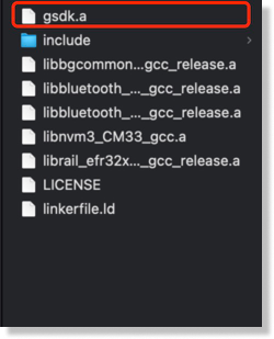
Currently we need to manually modify the replacement file, the subsequent direct download library can be used, please wait for our wiki update.
- [Replacement Files] gsdk.a
Changing the file path
- /Users/yourname/Library/Arduino15/packages/SiliconLabs/hardware/silabs/2.2.0/variants/xiao_mg24/ble_silabs/
Code Implementation
#include <mic.h>
#if defined(WIO_TERMINAL)
#include "processing/filters.h"
#endif

// Settings
#if defined(WIO_TERMINAL)
#define DEBUG 1                 // Enable pin pulse during ISR
#define SAMPLES 16000*3
#elif defined(ARDUINO_ARCH_NRF52840)
#define DEBUG 1                 // Enable pin pulse during ISR
#define SAMPLES 800
#elif defined(ARDUINO_SILABS)
#define DEBUG 1                 // Enable pin pulse during ISR
#define SAMPLES 800
#endif

mic_config_t mic_config{
  .channel_cnt = 1,
  .sampling_rate = 16000,
  .buf_size = 1600,
#if defined(WIO_TERMINAL)
  .debug_pin = 1                // Toggles each DAC ISR (if DEBUG is set to 1)
#elif defined(ARDUINO_ARCH_NRF52840)
  .debug_pin = LED_BUILTIN                // Toggles each DAC ISR (if DEBUG is set to 1)
#elif defined(ARDUINO_SILABS)
  .debug_pin = LED_BUILTIN                // Toggles each DAC ISR (if DEBUG is set to 1)
#endif
};

#if defined(WIO_TERMINAL)
DMA_ADC_Class Mic(&mic_config);
#elif defined(ARDUINO_ARCH_NRF52840)
NRF52840_ADC_Class Mic(&mic_config);
#elif defined(ARDUINO_SILABS)
MG24_ADC_Class Mic(&mic_config);
#endif

int16_t recording_buf[SAMPLES];
volatile uint8_t recording = 0;
volatile static bool record_ready = false;

#if defined(WIO_TERMINAL)
FilterBuHp filter;
#endif

void setup() {

  Serial.begin(115200);
  while (!Serial) {delay(10);}

#if defined(WIO_TERMINAL)
  pinMode(WIO_KEY_A, INPUT_PULLUP);
#endif

  Mic.set_callback(audio_rec_callback);

  if (!Mic.begin()) {
    Serial.println("Mic initialization failed");
    while (1);
  }

  Serial.println("Mic initialization done.");

}

void loop() {

#if defined(WIO_TERMINAL)
if (digitalRead(WIO_KEY_A) == LOW && !recording) {

    Serial.println("Starting sampling");
    recording = 1;
    record_ready = false;
}
#endif

#if defined(WIO_TERMINAL)
  if (!recording && record_ready)
#elif defined(ARDUINO_ARCH_NRF52840) || defined(ARDUINO_SILABS)
  if (record_ready)
#endif
  {
  Serial.println("Finished sampling");

  for (int i = 0; i < SAMPLES; i++) {

  //int16_t sample = filter.step(recording_buf[i]);
  int16_t sample = recording_buf[i];
  Serial.println(sample);
  }

  record_ready = false;
  }
}

static void audio_rec_callback(uint16_t *buf, uint32_t buf_len) {

  static uint32_t idx = 0;
  // Copy samples from DMA buffer to inference buffer
#if defined(WIO_TERMINAL)
  if (recording)
#endif
  {
    for (uint32_t i = 0; i < buf_len; i++) {

      // Convert 12-bit unsigned ADC value to 16-bit PCM (signed) audio value
#if defined(WIO_TERMINAL)
      recording_buf[idx++] = filter.step((int16_t)(buf[i] - 1024) * 16);
      //recording_buf[idx++] = (int16_t)(buf[i] - 1024) * 16;
#elif defined(ARDUINO_ARCH_NRF52840) || defined(ARDUINO_SILABS)
      recording_buf[idx++] = buf[i];
#endif

      if (idx >= SAMPLES){
      idx = 0;
      recording = 0;
      record_ready = true;
      break;
     }
    }
  }

}
Function Overview
Microphone Configuration
mic_config_t mic_config{
.channel_cnt = 1,
.sampling_rate = 16000,
.buf_size = 1600,
#if defined(WIO_TERMINAL)
.debug_pin = 1
#elif defined(ARDUINO_ARCH_NRF52840)
.debug_pin = LED_BUILTIN
#elif defined(ARDUINO_SILABS)
.debug_pin = LED_BUILTIN
#endif
};
- mic_config_t: Defines a microphone configuration structure.
- channel_cnt: set to 1 for mono.
- sampling_rate: Set to 16000 Hz for sampling frequency.
- buf_size: set to 1600 for buffer size.
- ebug_pin: set debug pin according to platform, used for signal indication during debugging.
Microphone instantiation
#if defined(WIO_TERMINAL)
DMA_ADC_Class Mic(&mic_config);
#elif defined(ARDUINO_ARCH_NRF52840)
NRF52840_ADC_Class Mic(&mic_config);
#elif defined(ARDUINO_SILABS)
MG24_ADC_Class Mic(&mic_config);
#endif
- Conditional compilation: create the appropriate microphone class instances for different platforms, using the previously defined configuration.
Recording buffers and flags
int16_t recording_buf[SAMPLES];
volatile uint8_t recording = 0;
volatile static bool record_ready = false;
- recording_buf: Define an array of SAMPLES to store recording samples.
- recording: a volatile variable that marks whether recording is currently in progress to prevent compiler optimization.
- record_ready: a volatile static variable that indicates if the recording is complete and ready for further processing.
Filter Example (for WIO Terminal)
#if defined(WIO_TERMINAL)
FilterBuHp filter;
#endif
- If on the WIO Terminal, create an instance of a high-pass filter for filter processing.
setup
void setup() {
Serial.begin(115200);
while (!Serial) {delay(10);}

#if defined(WIO_TERMINAL)
pinMode(WIO_KEY_A, INPUT_PULLUP);
#endif

Mic.set_callback(audio_rec_callback);

if (!Mic.begin()) {
  Serial.println("Mic initialization failed");
  while (1);
}

Serial.println("Mic initialization done.");
}
-Initialize Serial Port: Start serial communication at 115200 baud rate and wait for the serial port to be ready.
- Set Pin Mode: On WIO Terminal, set the key pins to input pull-up mode.
- Set callback function: call Mic.set_callback(audio_rec_callback) to specify the callback function when recording audio.
- Initialize the microphone: call Mic.begin(), if the initialization fails, print an error message and enter a dead loop.
loop
void loop() {
#if defined(WIO_TERMINAL)
if (digitalRead(WIO_KEY_A) == LOW && !recording) {
  Serial.println("Starting sampling");
  recording = 1;
  record_ready = false;
}
#endif

#if defined(WIO_TERMINAL)
if (!recording && record_ready)
#elif defined(ARDUINO_ARCH_NRF52840) || defined(ARDUINO_SILABS)
if (record_ready)
#endif
{
  Serial.println("Finished sampling");

  for (int i = 0; i < SAMPLES; i++) {
    int16_t sample = recording_buf[i];
    Serial.println(sample);
  }

  record_ready = false;
}
}
- Detect Key: On the WIO Terminal, starts recording when it detects that a key has been pressed and is not recording.
- Finished sampling:Prints “Finished sampling” if not recording and record_ready is set to true.
- Iterates through the recording buffer and prints each sample value.
Audio recording callback function
static void audio_rec_callback(uint16_t *buf, uint32_t buf_len) {
static uint32_t idx = 0;
#if defined(WIO_TERMINAL)
if (recording)
#endif
{
  for (uint32_t i = 0; i < buf_len; i++) {
    #if defined(WIO_TERMINAL)
    recording_buf[idx++] = filter.step((int16_t)(buf[i] - 1024) * 16);
    #elif defined(ARDUINO_ARCH_NRF52840) || defined(ARDUINO_SILABS)
    recording_buf[idx++] = buf[i];
    #endif

    if (idx >= SAMPLES){
      idx = 0;
      recording = 0;
      record_ready = true;
      break;
    }
  }
}
}
- Callback function: called during audio recording, responsible for copying samples from the DMA buffer to the recording buffer.
- Conditional Compilation: Processes the input using filters if on the WIO Terminal.
- Converts 12-bit unsigned ADC values to 16-bit PCM (signed) audio values.
- Sample Fill: copies samples into recording_buf and updates index idx.
- Finish recording: if the number of filled samples reaches SAMPLES, resets the index, marks the end of recording and sets record_ready to true.
Results Chart
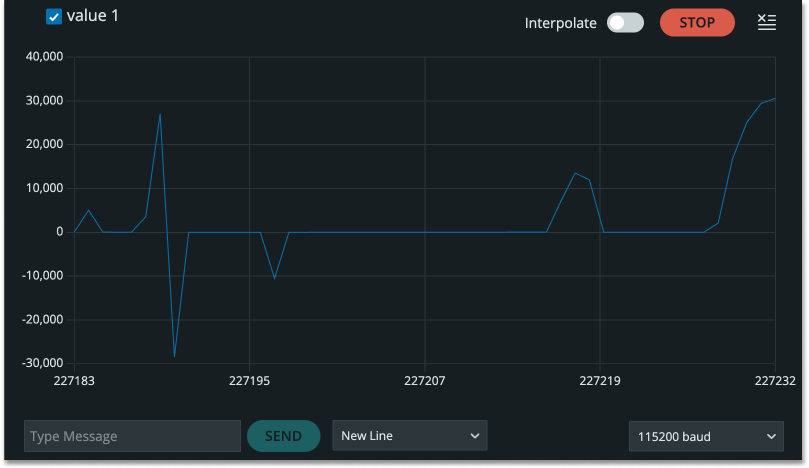
Here is the waveform of the recognized sound, when you blow, you can clearly see that the waveform oscillation amplitude becomes bigger.
Greater
If you want more sample code , Please Click : -> "Example -> Seeed Arduino Mic"
XIAO MG24 Sense Microphone(Silicon Labs Demo)
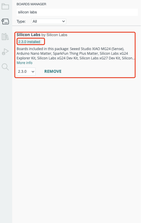
We need to download the latest on-board package (2.3.0) in order to find the latest official code in the example
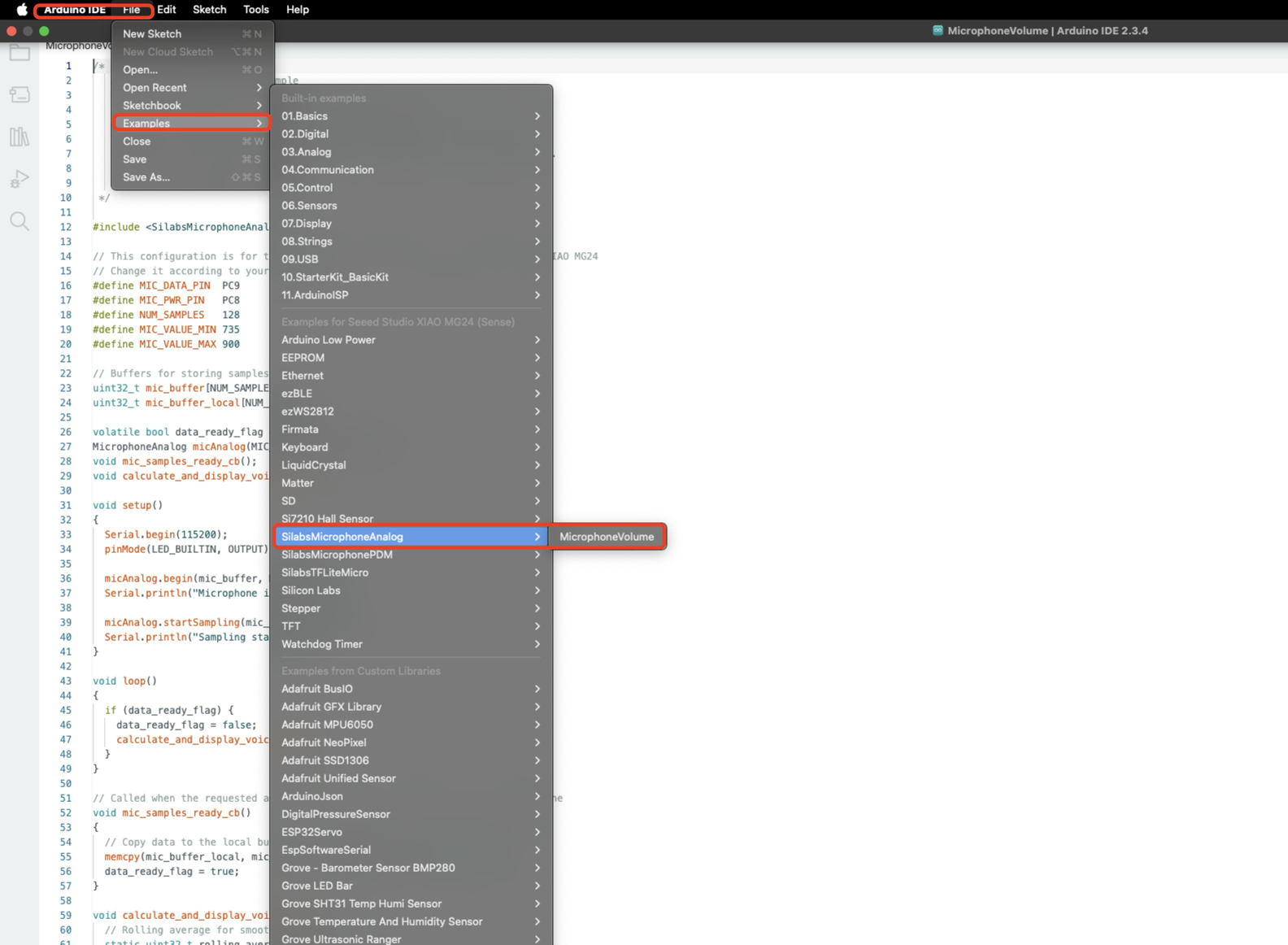
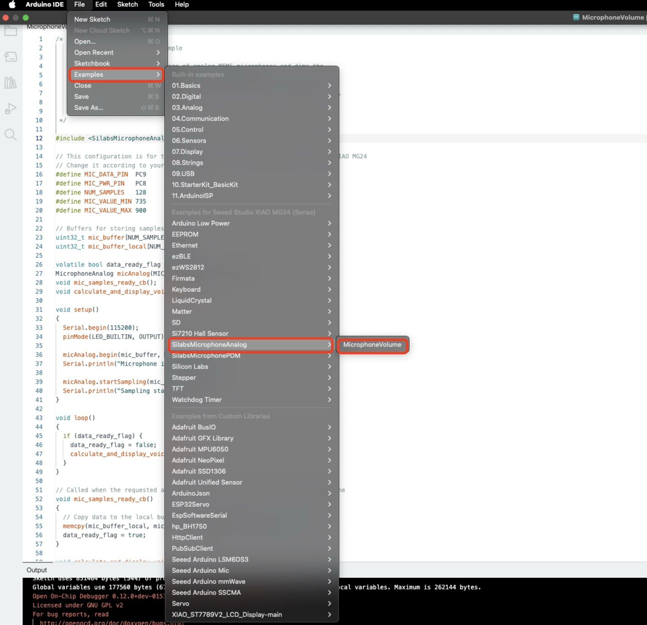
Software Preparation
Code Implementation
/*
   Analog microphone volume example

   The example showcases the usage of analog MEMS microphones and dims the
   on-board LED based on the microphone's input volume.
   This example is compatible with all Silicon Labs Arduino boards, however
   it requires an analog microphone on-board or connected to the specified pin.

   Author: Áron Gyapjas (Silicon Labs)
 */

#include <SilabsMicrophoneAnalog.h>

// This configuration is for the MSM381ACT001 microphone on the Seeed Studio XIAO MG24
// Change it according to your hardware
#define MIC_DATA_PIN  PC9
#define MIC_PWR_PIN   PC8
#define NUM_SAMPLES   128
#define MIC_VALUE_MIN 735
#define MIC_VALUE_MAX 900

// Buffers for storing samples
uint32_t mic_buffer[NUM_SAMPLES];
uint32_t mic_buffer_local[NUM_SAMPLES];

volatile bool data_ready_flag = false;
MicrophoneAnalog micAnalog(MIC_DATA_PIN, MIC_PWR_PIN);
void mic_samples_ready_cb();
void calculate_and_display_voice_level();

void setup()
{
  Serial.begin(115200);
  pinMode(LED_BUILTIN, OUTPUT);

  micAnalog.begin(mic_buffer, NUM_SAMPLES);
  Serial.println("Microphone initialized...");

  micAnalog.startSampling(mic_samples_ready_cb);
  Serial.println("Sampling started...");
}

void loop()
{
  if (data_ready_flag) {
    data_ready_flag = false;
    calculate_and_display_voice_level();
  }
}

// Called when the requested amount of samples are available from the microphone
void mic_samples_ready_cb()
{
  // Copy data to the local buffer in order to prevent it from overwriting
  memcpy(mic_buffer_local, mic_buffer, NUM_SAMPLES * sizeof(uint32_t));
  data_ready_flag = true;
}

void calculate_and_display_voice_level() {
  // Rolling average for smoothing the voice level
  static uint32_t rolling_average = 0u;

  // Stop sampling in order to prevent overwriting the current data
  micAnalog.stopSampling();

  // Get the average of the sampled values
  uint32_t voice_level = (uint32_t)micAnalog.getAverage(mic_buffer_local, NUM_SAMPLES);
  // Adjust the voice level relative to minimum/maximum of the microphone's output
  voice_level = constrain(voice_level, MIC_VALUE_MIN, MIC_VALUE_MAX);
  // Calculate the rolling average
  rolling_average = (voice_level + rolling_average) / 2;

  // Map the current average level to brightness
  int brightness = map(rolling_average, MIC_VALUE_MIN, MIC_VALUE_MAX, 0, 255);
  if (LED_BUILTIN_ACTIVE == LOW) {
    analogWrite(LED_BUILTIN, 255 - brightness);
  } else {
    analogWrite(LED_BUILTIN, brightness);
  }
  // Print the average voice level (you can use the Serial Plotter to view this value on a graph)
  Serial.println(rolling_average);

  // Restart sampling
  micAnalog.startSampling(mic_samples_ready_cb);
}
Function Overview
Header file introduction
#include <SilabsMicrophoneAnalog.h>
- Includes the
SilabsMicrophoneAnalog.hheader file, which contains the necessary library functions and definitions for using the analog microphone.
Hardware configuration
#define MIC_DATA_PIN  PC9
#define MIC_PWR_PIN   PC8
#define NUM_SAMPLES   128
#define MIC_VALUE_MIN 735
#define MIC_VALUE_MAX 900
-
MIC_DATA_PIN: Defines the microphone data pin asPC9. -
MIC_PWR_PIN: Defines the microphone power pin asPC8. -
NUM_SAMPLES: Defines the number of samples per sampling as 128. -
MIC_VALUE_MINandMIC_VALUE_MAX: Define the minimum and maximum range of the microphone output.
Buffer Definition
uint32_t mic_buffer[NUM_SAMPLES];
uint32_t mic_buffer_local[NUM_SAMPLES];
-
mic_buffer: Used to store raw sample data collected from the microphone. -
mic_buffer_local: Used to temporarily store sample data to prevent overwriting.
Flags and object definitions
volatile bool data_ready_flag = false;
MicrophoneAnalog micAnalog(MIC_DATA_PIN, MIC_PWR_PIN);
-
data_ready_flag: A flag to indicate whether new sample data is ready. -
micAnalog: Creates a MicrophoneAnalog object to control the microphone.
Callback Function Declaration
void mic_samples_ready_cb();
void calculate_and_display_voice_level();
-
mic_samples_ready_cb(): A callback function called when sampling is complete. -
calculate_and_display_voice_level(): A function to calculate the volume and control the LED brightness.
setup() function
void setup()
{
  Serial.begin(115200);
  pinMode(LED_BUILTIN, OUTPUT);

  micAnalog.begin(mic_buffer, NUM_SAMPLES);
  Serial.println("Microphone initialized...");

  micAnalog.startSampling(mic_samples_ready_cb);
  Serial.println("Sampling started...");
}
-
Initializes serial communication with a baud rate of 115200.
-
Sets the onboard LED pin to output mode.
-
Initializes the microphone and specifies the sample buffer.
-
Starts sampling and sets the callback function for when sampling is complete.
loop()function
void loop()
{
  if (data_ready_flag) {
    data_ready_flag = false;
    calculate_and_display_voice_level();
  }
}
-
Checks if
data_ready_flagistrue, indicating that new data is ready. -
If new data is available, calls the
calculate_and_display_voice_level()function to process the data.
void mic_samples_ready_cb()
{
  memcpy(mic_buffer_local, mic_buffer, NUM_SAMPLES * sizeof(uint32_t));
  data_ready_flag = true;
}
Copies sample data from mic_buffer to mic_buffer_local to prevent overwriting.
Sets data_ready_flag to true to indicate that new data is ready.
void calculate_and_display_voice_level() {
  static uint32_t rolling_average = 0u;

  micAnalog.stopSampling();

  uint32_t voice_level = (uint32_t)micAnalog.getAverage(mic_buffer_local, NUM_SAMPLES);
  voice_level = constrain(voice_level, MIC_VALUE_MIN, MIC_VALUE_MAX);
  rolling_average = (voice_level + rolling_average) / 2;

  int brightness = map(rolling_average, MIC_VALUE_MIN, MIC_VALUE_MAX, 0, 255);
  if (LED_BUILTIN_ACTIVE == LOW) {
    analogWrite(LED_BUILTIN, 255 - brightness);
  } else {
    analogWrite(LED_BUILTIN, brightness);
  }
  Serial.println(rolling_average);

  micAnalog.startSampling(mic_samples_ready_cb);
}
-
Stops sampling to prevent data overwriting.
-
Calculates the average of the sample data and constrains it between
MIC_VALUE_MINandMIC_VALUE_MAX. -
Calculates a rolling average to smooth out volume changes.
-
Maps the rolling average to the LED brightness range (0 to 255) and adjusts the LED brightness.
-
Outputs the rolling average via serial for observing volume changes.
-
Restarts sampling to collect new audio data.
Results Chart
When we blow into the microphone, we can see that the led on top will lighten and darken with the sound.
Greater
If you want more sample code , Please Click : -> "Example -> SilabsMicrophoneAnalog -> MicrophoneVolume"
Resources
For Seeed Studio XIAO MG24 Sense
- 📄 [PDF] Seeed Studio 6-Axis IMU(LSM6DS3TR-C) datasheet
- 📄 [PDF] Seeed Studio Analog Microphone(MSM381ACT001) datasheet
Tech Support & Product Discussion
Thank you for choosing our products! We are here to provide you with different support to ensure that your experience with our products is as smooth as possible. We offer several communication channels to cater to different preferences and needs.