Seeed Studio XIAO MG24 Sense With MicroPython
MicroPython is a Python interprer with a partial native code compilation feature. It provides a subset of Python 3.5 features, implemented for embedded processors and constrained systems. It is different from CircuitPython and you can read more about the differences in the MicroPython documentation.
Using MicroPython with XIAO MG24
Next, I will guide you through how to use MicroPython on the XIAO MG24 Senese and program it with Thonny IDE, based on the Windows operating system.
Hardware Preparation
| Seeed Studio XIAO MG24 Sense |
|---|
 |
Install Thonny IDE
Choose the appropriate version for installation. Here, I am installing it on a Windows system, so I have selected the Windows version.
Follow the instructions for the desired Python version.
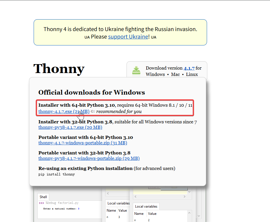
Then, simply follow the default steps for configuration.
Download the repository
Clone it to the local machine, and then remember the path where this XIAO MG24 MicroPython is stored. This path will be used later.
git clone https://github.com/Seeed-Studio/micropython-seeed-boards.git
LED Blinking Example
Here we will show you how to light up the USER LED on the XIAO MG24 using MicroPython with Thonny IDE.
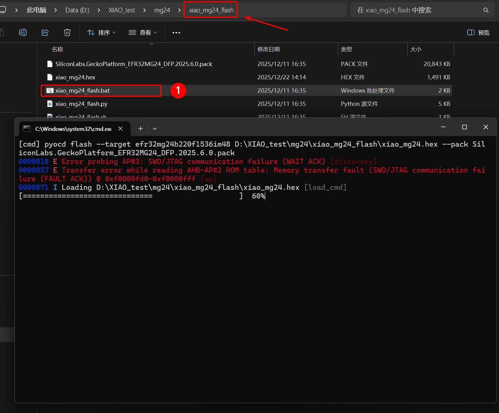
Step 1. Flash the MicroPython firmware
-
Download the XIAO MG24 MicroPython Firmware package and extract it to the appropriate location.Then open the terminal in this folder.
-
Press and hold the onboard RESET button on the XIAO MG24, then power it on.
-
For Windows: Click the
xiao_mg24_flash.bat. Release the RESET button when the script starts executing and wait for the programming to complete.
- For Mac / Linux
sudo chmod +x xiao_mg24_flash.sh && ./xiao_mg24_flash.sh
The error that occurs is determined by the internal architecture of the EFR32MG24 chip. This chip incorporates a protected security subsystem (Secure Vault), which corresponds to the AP#2 and AP#3 ports of the debug interface. When the pyOCD tool scans the device, it attempts to connect to all ports; however, these secure ports are locked or restricted and thus reject the connection requests, resulting in error logs. This does not affect the normal programming and execution of the main program (AP#0) and is a known and expected behavior.
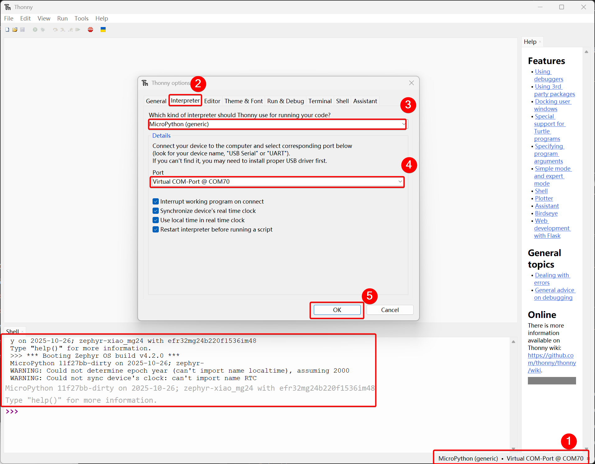
Step 2. Interpreter Configuration
Open Thonny IDE, then click the bottom right corner of the interface to configure the interpreter options. Select MicroPython (generic) and Port. After successful configuration, the MicroPython version information will be displayed in the Shell.
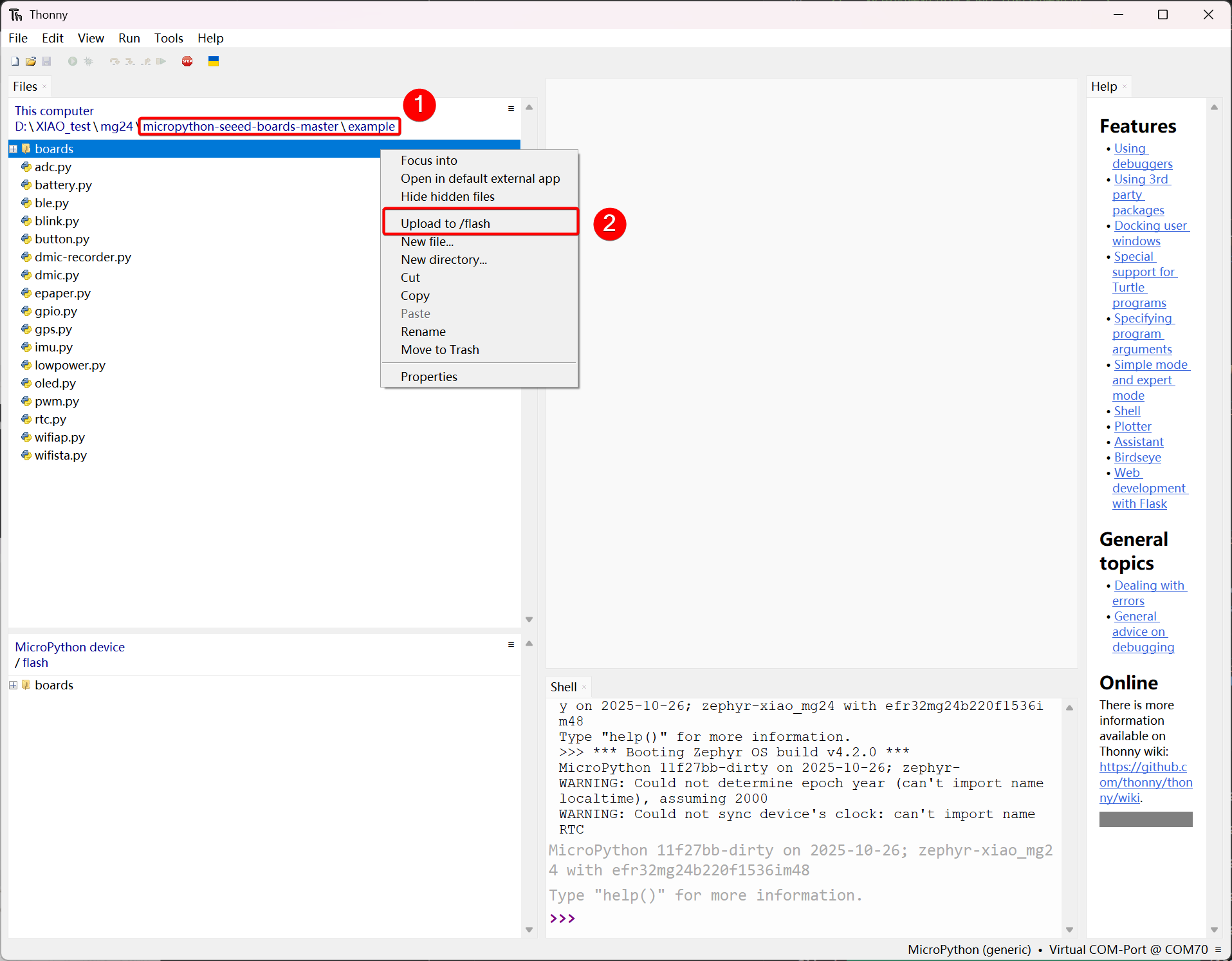
Step 3. Upload the boards file
- Open the view, select File, and the file manager path will be displayed on the left sidebar.
- Open the path of the cloned or downloaded file, and open
micropython-seeed-boards-master\examples - Select the boards folder and upload it to the flash. Then, you will be able to see the uploaded file on the MicroPython device/flash.
Step 4. Run the Code
Click File -> New to create a new file and save it as blink.py.
import time
from boards.xiao import XiaoPin

led = "led"

try:
    # Initialize LED
    led = XiaoPin(led, XiaoPin.OUT)
    while True:
        # LED 0.5 seconds on, 0.5 seconds off
        led.value(1)
        time.sleep(0.5)
        led.value(0)
        time.sleep(0.5)
except KeyboardInterrupt:
    print("\nProgram interrupted by user")
except Exception as e:
    print("\nError occurred: %s" % {e})
finally:
    led.value(1)
Code Explain:
-
Import Modules
timeImports the time moduleXiao PinImports the pin control class for the Seeed Xiao development board from the boards.xiao module, which is used to operate the pins on the board.
-
Define Pins
led = "led""Specifies that the pin is connected to theledpin of the development board (here, the USER pin)
-
Main Logic (try block)
- The USER LED will blink at 0.5-second intervals.
Copy the above code, then click the green button or press F5 to run it.
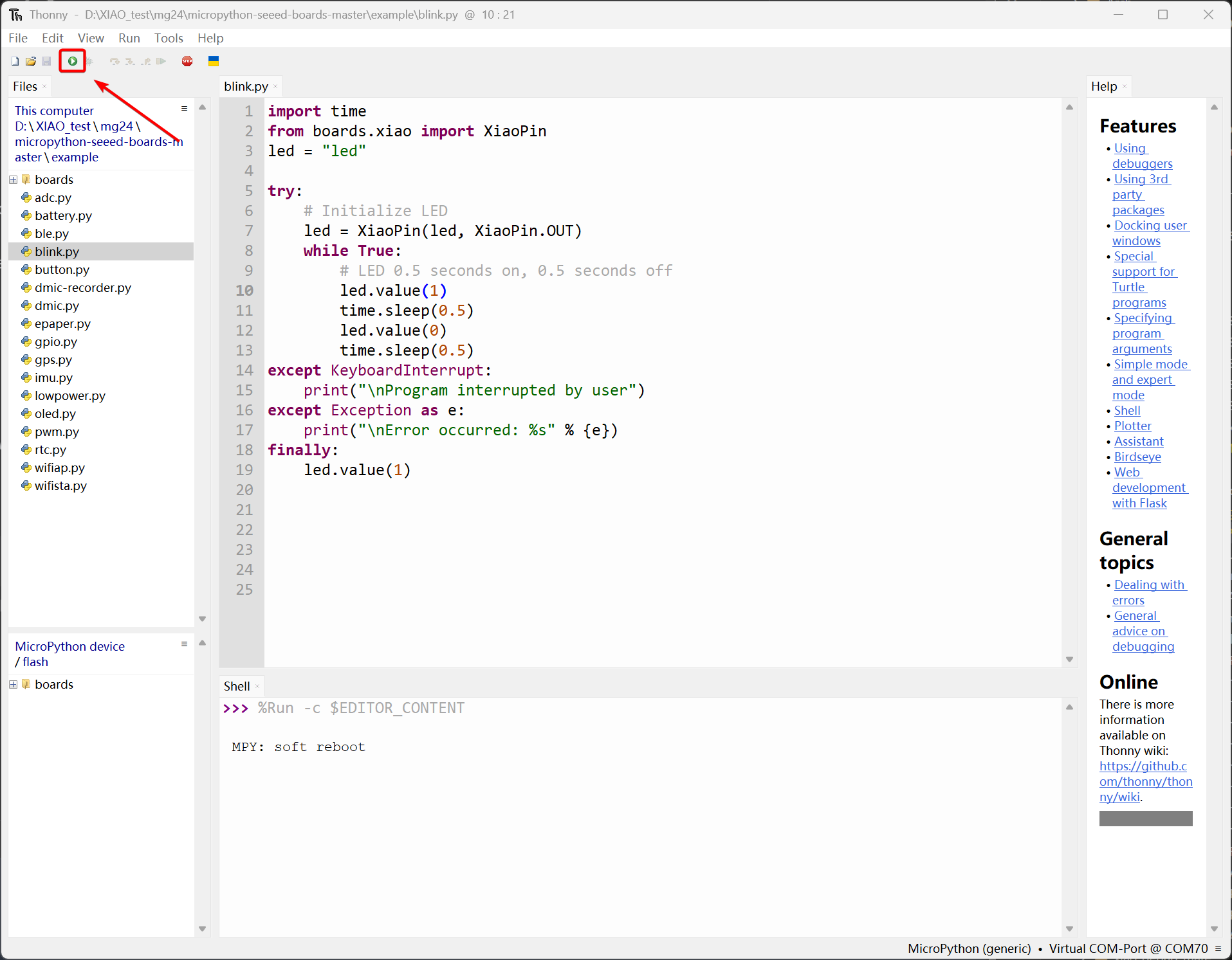
Once the code starts running, the USER LED will blink at 0.5-second intervals.
The result is as follows:
PWM Example
All GPIO pins on XIAO MG24 Sense support PWM output. Therefore, you can use any pin to output PWM to adjust the brightness of lights, control servos, and other functions.
Hardware Preparation
| Seeed Studio XIAO MG24 Sense | Seeed Studio Grove Base for XIAO | Grove - Variable Color LED |
|---|---|---|
|  |  |
Software
- Create a new file named pwm.py and copy the reference code into it.
import time
from boards.xiao import XiaoPWM

PIN = 0  # D0

# set the frequency and period of the PWM signal
FREQ = 1000
PERIOD_NS = int(1_000_000_000 // FREQ)
# set the number of steps to fade the LED and the delay between steps
FADE_STEPS = 255
STEP_DELAY = 0.01
STEP_SIZE = 3

pwm = None

try:
    # initialize the PWM with a frequency and a 0% duty cycle
    pwm = XiaoPWM(PIN)
    pwm.init(freq=FREQ, duty_ns=0)

    while True:
        # fade the LED in and out
        for fade in range(0, FADE_STEPS + 1, STEP_SIZE):
            duty_ns = (fade * PERIOD_NS) // FADE_STEPS

            if duty_ns < 0:
                duty_ns = 0
            elif duty_ns > PERIOD_NS:
                duty_ns = PERIOD_NS
            pwm.duty_ns(int(duty_ns))
            time.sleep(STEP_DELAY)
        # fade the LED in and out again
        for fade in range(FADE_STEPS, -1, -STEP_SIZE):
            duty_ns = (fade * PERIOD_NS) // FADE_STEPS
            if duty_ns < 0:
                duty_ns = 0
            elif duty_ns > PERIOD_NS:
                duty_ns = PERIOD_NS
            pwm.duty_ns(int(duty_ns))
            time.sleep(STEP_DELAY)

except KeyboardInterrupt:
    print("\nProgram interrupted by user")

except Exception as e:

    print("\nError occurred:", repr(e))

finally:
    if pwm is not None:
        try:
            pwm.deinit()
        except Exception:
            pass
Code Explain:
-
Import Modules
time: Imports the standard time module to handle delays (used for controlling the speed of the breathing effect).XiaoPWM: Imports the PWM (Pulse Width Modulation) control class from theboards.xiaomodule, used to generate analog-like signals on the digital pin.
-
Define Pins & Constants
PIN = 0: Specifies that the device is connected to pin D0 on the development board. -FREQ / PERIOD_NS: Sets the PWM frequency to 1000 Hz and calculates the total period in nanoseconds (1 second / 1000).FADE_STEPS / STEP_DELAY: Configures the animation resolution (255 steps) and the speed (0.01s wait between changes).
-
Main Logic (try block)
- Initialization: The code initializes the PWM object on pin D0 starting with 0% brightness (duty cycle).
- Breathing Loop: Inside the infinite
while Trueloop, twoforloops control the LED brightness:- Fade In: Gradually increases the
duty_ns(pulse width) from 0 to the full period duration. - Fade Out: Gradually decreases the
duty_nsfrom the full period back to 0.
- Fade In: Gradually increases the
-
Duty Cycle Calculation: The formula
(fade * PERIOD_NS) // FADE_STEPSmaps the loop step (0-255) to the required nanosecond timing for the PWM hardware.- Safety/Cleanup: The
finallyblock ensurespwm.deinit()is called to release hardware resources if the program is stopped (e.g., via Ctrl+C).
- Safety/Cleanup: The
Result graph
After the program runs, the LED will achieve a fading effect, and you can adjust the PWM step size according to your actual needs.
Analog Example
XIAO MG24 Sense Development Board have to 12 bit ADC for high-resolution reading of analog sensor values , it can help us to read more accurate values.
Next , We will choose two sensors to reflect the characteristics of ADC .
Hardware Preparation
| Seeed Studio XIAO MG24 Sense | Seeed Studio Grove Base for XIAO | Grove - Variable Color LED | Grove-Rotary Angle Sensor |
|---|---|---|---|
| | |  |
Software
- Create a new file named adc.py and copy the reference code into it.
import time
from boards.xiao import XiaoPin, XiaoADC, XiaoPWM

adc_pin = 0
pwm_pin = 1

try:
    adc = XiaoADC(adc_pin)
    pwm = XiaoPWM(pwm_pin)

    FREQ = 1000
    PERIOD_NS = 1000000000 // FREQ
    pwm.init(freq=FREQ, duty_ns=0)

    MAX_VOLTAGE = 3.3
    DEAD_ZONE = 0.02
    last_duty = -1

    while True:
        raw_value = adc.read_u16()
        voltage = (raw_value / 65535.0) * MAX_VOLTAGE

        # Calculate the base percentage (0.0 - 1.0)
        duty_percent = voltage / MAX_VOLTAGE

        # scope limitation
        if duty_percent < 0: duty_percent = 0
        if duty_percent > 1: duty_percent = 1

        if abs(duty_percent - last_duty) < DEAD_ZONE:
            time.sleep(0.05)
            continue

        inverted_duty = 1.0 - duty_percent
        duty_ns = int(inverted_duty * PERIOD_NS)

        if duty_ns < 20: duty_ns = 20
        elif duty_ns > (PERIOD_NS * 0.96): duty_ns = int(PERIOD_NS * 0.96)

        pwm.duty_ns(duty_ns)

        print("Voltage: {:.2f}V, Brightness: {:.1f}%".format(voltage, duty_percent * 100))

        last_duty = duty_percent
        time.sleep(0.05)

except KeyboardInterrupt:
    print("\nProgram interrupted by user")
except Exception as e:
    print("\nError occurred: {}".format(e))
finally:
    pwm.deinit()
-
Import Modules
time: Imports the standard time module to handle delays (used for controlling the speed of the breathing effect).XiaoPWM: Imports the PWM (Pulse Width Modulation) control class from theboards.xiaomodule, used to generate analog-like signals on the digital pin. Code Explain:
-
Import Modules
time: Imports the standard time module to handle delays (used to control the sampling rate of the loop).XiaoADC,XiaoPWM: Imports the hardware control classes from theboards.xiaomodule.XiaoADChandles the analog input (potentiometer), andXiaoPWMhandles the pulse width modulation output (LED).
-
Define Pins & Constants
adc_pin = 0/pwm_pin = 1: Maps the physical pins. Pin D0 is used for the input sensor, and Pin D1 is used for the output LED.FREQ / PERIOD_NS: Sets the PWM operating frequency to 1000 Hz and calculates the period duration in nanoseconds (1,000,000 ns).MAX_VOLTAGE / DEAD_ZONE: Defines the reference voltage (3.3V) and a 2% dead zone threshold to filter out electrical noise and prevents the LED from flickering.
-
Main Logic (try block)
- Initialization: Sets up the ADC and PWM objects. The PWM starts with a duty cycle of 0.
- Control Loop: Inside the
while Trueloop, the code continuously monitors the sensor:- Read & Normalize: Reads the raw 16-bit integer (0-65535) from the ADC and converts it into a floating-point voltage (0.0V - 3.3V).
- Jitter Filter: Compares the current reading with
last_duty. If the change is less than theDEAD_ZONE, the loop skips the update to maintain stability.
-
Duty Cycle Calculation & Logic Inversion
- Active Low Logic: The line
inverted_duty = 1.0 - duty_percentreverses the logic. - Reason: Your LED is likely Active Low (connected to VCC).
- Effect: As voltage increases,
duty_nsbecomes smaller (pulling the pin LOW for longer), making the LED brighter.
- Active Low Logic: The line
-
Safety Clamps: The code limits the output signal between a minimum of 20ns and a maximum of 96% of the period. This protects the hardware and ensures the signal remains within a valid range.
-
Output & Cleanup
- Feedback: Prints the current voltage and brightness percentage to the console using
.format()for compatibility with older MicroPython versions. - Safety/Cleanup: The
finallyblock guarantees thatpwm.deinit()is executed when the program stops, safely turning off the PWM hardware resources.
- Feedback: Prints the current voltage and brightness percentage to the console using
Result graph
- Rotate the Grove-Rotary Angle Sensor, and the brightness of the LED will change accordingly.
- The Shell window will also print the voltage and brightness percentage.

UART Example
UART is one of the most commonly used communication protocols. It allows data transmission with just two data lines, and its low cost makes it widely used in many fields. Next, we will demonstrate the application of serial communication by taking the transmission of GPS module data as an example.
Hardware Preparation
| Seeed Studio XIAO MG24 Sense | L76K GNSS Module for Seeed Studio XIAO |
|---|---|
| 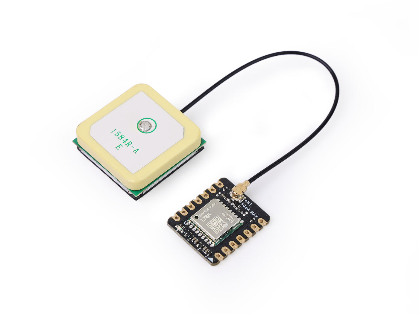 |
Software
- Create a new file named uart.py and copy the reference code into it.
Reference Code
from boards.xiao import XiaoUART
import time
import math

uart = "uart1"
baudrate = 9600
tx = 6              # D6
rx = 7              # D7

# Coordinate structure
class Coordinates:
    def __init__(self, Lon=0.0, Lat=0.0):
        self.Lon = Lon
        self.Lat = Lat

# GPS data structure
class GNRMC:
    def __init__(self):
        self.Lon = 0.0      # GPS Longitude
        self.Lat = 0.0      # GPS Latitude
        self.Lon_area = ''  # E or W
        self.Lat_area = ''  # N or S
        self.Time_H = 0     # Time Hour
        self.Time_M = 0     # Time Minute
        self.Time_S = 0     # Time Second
        self.Status = 0     # 1: Successful positioning, 0: Positioning failed

# Convert WGS-84 to GCJ-02
def transformLat(x, y):
    ret = -100.0 + 2.0 * x + 3.0 * y + 0.2 * y * y + 0.1 * x * y + 0.2 * math.sqrt(abs(x))
    ret += (20.0 * math.sin(6.0 * x * pi) + 20.0 * math.sin(2.0 * x * pi)) * 2.0 / 3.0
    ret += (20.0 * math.sin(y * pi) + 40.0 * math.sin(y / 3.0 * pi)) * 2.0 / 3.0
    ret += (160.0 * math.sin(y / 12.0 * pi) + 320 * math.sin(y * pi / 30.0)) * 2.0 / 3.0
    return ret

# Convert WGS-84 to GCJ-02
def transformLon(x, y):
    ret = 300.0 + x + 2.0 * y + 0.1 * x * x + 0.1 * x * y + 0.1 * math.sqrt(abs(x))
    ret += (20.0 * math.sin(6.0 * x * pi) + 20.0 * math.sin(2.0 * x * pi)) * 2.0 / 3.0
    ret += (20.0 * math.sin(x * pi) + 40.0 * math.sin(x / 3.0 * pi)) * 2.0 / 3.0
    ret += (150.0 * math.sin(x / 12.0 * pi) + 300.0 * math.sin(x / 30.0 * pi)) * 2.0 / 3.0
    return ret

# Convert GCJ-02 to BD-09
def bd_encrypt(gg):
    bd = Coordinates()
    x = gg.Lon
    y = gg.Lat
    z = math.sqrt(x * x + y * y) + 0.00002 * math.sin(y * x_pi)
    theta = math.atan2(y, x) + 0.000003 * math.cos(x * x_pi)
    bd.Lon = z * math.cos(theta) + 0.0065
    bd.Lat = z * math.sin(theta) + 0.006
    return bd

# Convert WGS-84 to GCJ-02
def transform(gps):
    gg = Coordinates()
    dLat = transformLat(gps.Lon - 105.0, gps.Lat - 35.0)
    dLon = transformLon(gps.Lon - 105.0, gps.Lat - 35.0)
    radLat = gps.Lat / 180.0 * pi
    magic = math.sin(radLat)
    magic = 1 - ee * magic * magic
    sqrtMagic = math.sqrt(magic)
    dLat = (dLat * 180.0) / ((a * (1 - ee)) / (magic * sqrtMagic) * pi)
    dLon = (dLon * 180.0) / (a / sqrtMagic * math.cos(radLat) * pi)
    gg.Lat = gps.Lat + dLat
    gg.Lon = gps.Lon + dLon
    return gg

# Convert to Baidu coordinates (BD-09)
def L76X_Baidu_Coordinates(gps):
    wgs84_coords = Coordinates(gps.Lon, gps.Lat)
    gcj02_coords = transform(wgs84_coords)
    bd09_coords = bd_encrypt(gcj02_coords)
    return bd09_coords

# Convert to Google coordinates (GCJ-02)
def L76X_Google_Coordinates(gps):
    wgs84_coords = Coordinates(gps.Lon, gps.Lat)
    gcj02_coords = transform(wgs84_coords)
    return gcj02_coords

# Parse GNRMC NMEA sentence
def parse_gnrmc(nmea_sentence):
    gps = GNRMC()

    if not nmea_sentence.startswith(b'$GNRMC') and not nmea_sentence.startswith(b'$PNRMC'):
        return gps

    try:
        # Convert to string and split by commas
        sentence_str = nmea_sentence.decode('ascii', 'ignore')
        fields = sentence_str.split(',')

        if len(fields) < 12:
            return gps

        # Parse time field (HHMMSS.sss)
        if fields[1]:
            time_str = fields[1]
            if '.' in time_str:
                time_str = time_str.split('.')[0]
            if len(time_str) >= 6:
                gps.Time_H = int(time_str[0:2]) + 8  # GMT+8
                gps.Time_M = int(time_str[2:4])
                gps.Time_S = int(time_str[4:6])
                if gps.Time_H >= 24:
                    gps.Time_H -= 24

        # Parse status
        gps.Status = 1 if fields[2] == 'A' else 0

        if gps.Status == 1:
            # Parse latitude (DDMM.MMMMM)
            if fields[3] and fields[4]:
                lat_str = fields[3]
                if '.' in lat_str:
                    degrees = float(lat_str[0:2])
                    minutes = float(lat_str[2:])
                    gps.Lat = degrees + minutes / 60.0
                    gps.Lat_area = fields[4]

            # Parse longitude (DDDMM.MMMMM)
            if fields[5] and fields[6]:
                lon_str = fields[5]
                if '.' in lon_str:
                    degrees = float(lon_str[0:3])
                    minutes = float(lon_str[3:])
                    gps.Lon = degrees + minutes / 60.0
                    gps.Lon_area = fields[6]

    except Exception as e:
        print("Parse error:", e)

    return gps

# Print formatted GPS data
def print_gps_data(gps):
    print("\n--- GPS Data ---")
    print("Time (GMT+8): {:02d}:{:02d}:{:02d}".format(gps.Time_H, gps.Time_M, gps.Time_S))
    if gps.Status == 1:
        print("Latitude (WGS-84): {:.6f} {}".format(gps.Lat, gps.Lat_area))
        print("Longitude (WGS-84): {:.6f} {}".format(gps.Lon, gps.Lon_area))

        # Coordinate conversion
        baidu_coords = L76X_Baidu_Coordinates(gps)
        google_coords = L76X_Google_Coordinates(gps)

        print("Baidu Latitude: {:.6f}".format(baidu_coords.Lat))
        print("Baidu Longitude: {:.6f}".format(baidu_coords.Lon))
        print("Google Latitude: {:.6f}".format(google_coords.Lat))
        print("Google Longitude: {:.6f}".format(google_coords.Lon))
        print("GPS positioning successful.")
    else:
        print("GPS positioning failed or no valid data.")

try:
    uart = XiaoUART(uart, baudrate, tx, rx)
    # Initialize UART
    uart.init(9600, bits=8, parity=None, stop=1)
    # Buffer to accumulate complete messages
    buffer = bytearray()
    # Constants for coordinate transformation
    pi = 3.14159265358979324
    a = 6378245.0
    ee = 0.00669342162296594323
    x_pi = 3.14159265358979324 * 3000.0 / 180.0
    while True:
        available = uart.any()
        if available > 0:
            # Read all available bytes
            data = uart.read(available)
            buffer.extend(data)
            # Check if we have a complete line (ends with newline)
            if b'\n' in buffer:
                # Find the newline position
                newline_pos = buffer.find(b'\n')
                # Extract the complete message
                complete_message = buffer[:newline_pos + 1]
                # Remove the processed part from buffer
                buffer = buffer[newline_pos + 1:]
                # Parse GNRMC sentences
                if complete_message.startswith(b'$GNRMC') or complete_message.startswith(b'$PNRMC'):
                    gps_data = parse_gnrmc(complete_message)
                    print_gps_data(gps_data)
except KeyboardInterrupt:
    print("\nProgram interrupted by user")
except Exception as e:
    print("\nError occurred: %s" % {e})
finally:
    uart.deinit()
Code Explain:
-
Import Modules
XiaoUARTImports the UART communication class for the Seeed Xiao development board from theboards.xiaomodule, used to initialize and control serial communication.timeImports the time module to support timing-related functions (though not directly used here, it’s imported for potential future use or compatibility).mathImports mathematical functions (sin,cos,sqrt,atan2, etc.) required for coordinate transformation algorithms.
-
Define UART Configuration
uart = "uart1"Specifies the UART controller instance to use — here,uart1.baudrate = 9600Sets the baud rate for serial communication to 9600 bps.tx = 6Specifies that the UART transmit pin (TX) is connected to digital pin D6.rx = 7Specifies that the UART receive pin (RX) is connected to digital pin D7.
-
Define Data Structures
CoordinatesClass: A simple container for storing longitude/latitude values as floating-point numbers.GNRMCClass: Represents parsed GPS data from a$GNRMCNMEA sentence. Contains:- Latitude/Longitude in decimal degrees
- Hemisphere indicators (
N/S,E/W) - Time (hour, minute, second — adjusted to GMT+8)
- Status flag (1 = valid fix, 0 = no fix)
-
Coordinate Transformation Functions
transformLat(x, y)&transformLon(x, y)— Helper functions implementing part of the WGS-84 → GCJ-02 conversion algorithm (used in China for map obfuscation).bd_encrypt(gg)— Converts GCJ-02 coordinates to Baidu’s BD-09 coordinate system by applying additional offset and rotation.transform(gps)— Main function converting WGS-84 (raw GPS) coordinates to GCJ-02 using complex trigonometric formulas based on elliptical Earth model.L76X_Baidu_Coordinates(gps)— Wrapper that converts raw GPS (WGS-84) → GCJ-02 → BD-09 (Baidu Maps format).L76X_Google_Coordinates(gps)— Wrapper that converts raw GPS (WGS-84) → GCJ-02 (Google Maps format in China).
-
Parse GNRMC Sentence
parse_gnrmc(nmea_sentence)— Parses a raw NMEA$GNRMCor$PNRMCstring into structuredGNRMCobject.- Extracts time (converts from UTC to GMT+8).
- Checks status (
A= active/valid fix,V= invalid). - Parses latitude/longitude from DDMM.MMMMM format → decimal degrees.
- Returns populated
GNRMCobject or default empty one if parsing fails.
-
Display Formatted GPS Data
print_gps_data(gps)— Prints human-readable GPS info including:- Local time (GMT+8)
- Raw WGS-84 coordinates with hemisphere
- Converted GCJ-02 (Google-compatible) and BD-09 (Baidu-compatible) coordinates
- Status message indicating whether positioning succeeded
-
Main Logic (try block)
- Initializes UART interface with specified parameters.
- Defines global constants needed for coordinate math (
pi,a,ee,x_pi) — Earth ellipsoid parameters and scaling factors. - Enters infinite loop to continuously read incoming GPS data via UART.
- Uses
bufferto accumulate partial messages until a complete line (ending with\n) is received. - When a complete line arrives:
- Checks if it starts with
$GNRMCor$PNRMC - If so, parses it using
parse_gnrmc() - Displays formatted output via
print_gps_data()
- Checks if it starts with
- Uses
- Handles exceptions:
KeyboardInterrupt: Gracefully exits on Ctrl+C.- General
Exception: Catches and prints any unexpected errors.
- Finally, calls
uart.deinit()to clean up UART resources before exiting.
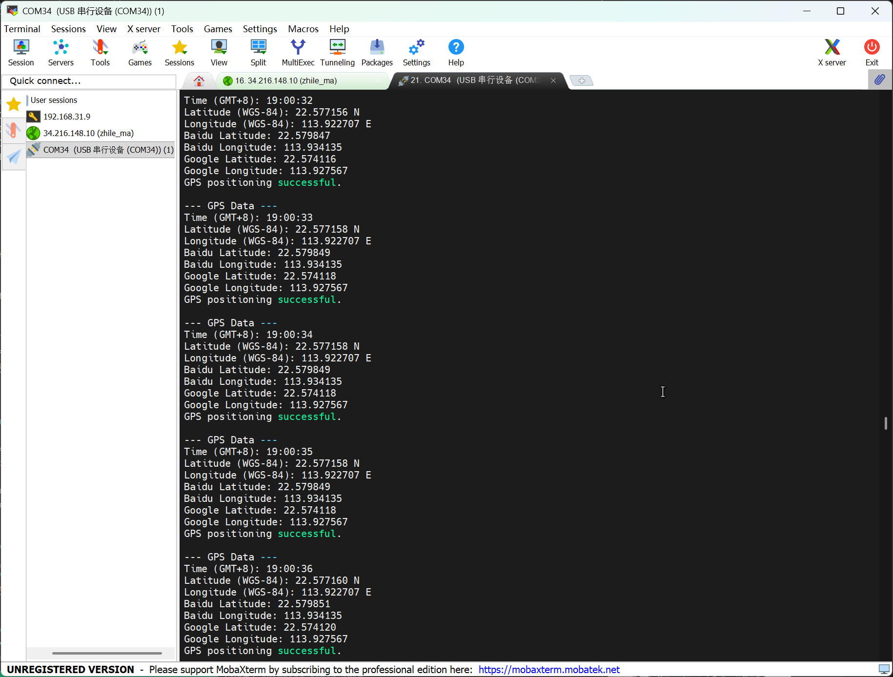
Result graph
- Open any serial port tool and set the baud rate to 9600.
- The GPS module should be used in an open outdoor area.
- The program will print the GPS information of your location.
I2C Example
XIAO MG24 Sense has an I2C interface that can be used for data transmission and parsing of many sensors, as well as for using OLED screens.
Hardware Preparation
| Seeed Studio XIAO MG24 Sense | Seeed Studio Expansion Base for XIAO with Grove OLED |
|---|---|
|  |
Software
- Create a new file named i2c.py and copy the reference code into it.
Reference Code
import time
from boards.xiao import XiaoI2C

sda = 4        #D4
scl = 5        #D5
i2c = "i2c0"
frq = 400000
i2c = XiaoI2C(i2c, sda, scl, frq)

# --- SSD1306 I2C address and command definitions ---
SSD1306_I2C_ADDR = 0x3C
SSD1306_SET_CONTRAST = 0x81
SSD1306_DISPLAY_ALL_ON_RESUME = 0xA4
SSD1306_DISPLAY_ALL_ON = 0xA5
SSD1306_NORMAL_DISPLAY = 0xA6
SSD1306_INVERT_DISPLAY = 0xA7
SSD1306_DISPLAY_OFF = 0xAE
SSD1306_DISPLAY_ON = 0xAF
SSD1306_SET_DISPLAY_OFFSET = 0xD3
SSD1306_SET_COM_PINS = 0xDA
SSD1306_SET_VCOM_DETECT = 0xDB
SSD1306_SET_DISPLAY_CLOCK_DIV = 0xD5
SSD1306_SET_PRECHARGE = 0xD9
SSD1306_SET_MULTIPLEX = 0xA8
SSD1306_SET_LOW_COLUMN = 0x00
SSD1306_SET_HIGH_COLUMN = 0x10
SSD1306_SET_START_LINE = 0x40
SSD1306_MEMORY_MODE = 0x20
SSD1306_COLUMN_ADDR = 0x21
SSD1306_PAGE_ADDR = 0x22
SSD1306_COM_SCAN_INC = 0xC0
SSD1306_COM_SCAN_DEC = 0xC8
SSD1306_SEG_REMAP = 0xA0
SSD1306_CHARGE_PUMP = 0x8D

# Display dimensions
SSD1306_WIDTH = 128
SSD1306_HEIGHT = 64
SSD1306_PAGES = 8

# Basic 8x8 font
font_data = {
    ' ': [0x00,0x00,0x00,0x00,0x00,0x00,0x00,0x00],
    'A': [0x18,0x24,0x42,0x7E,0x42,0x42,0x42,0x00],
    'B': [0x7C,0x42,0x42,0x7C,0x42,0x42,0x7C,0x00],
    'C': [0x3C,0x42,0x40,0x40,0x40,0x42,0x3C,0x00],
    'D': [0x78,0x44,0x42,0x42,0x42,0x44,0x78,0x00],
    'E': [0x7C,0x40,0x40,0x78,0x40,0x40,0x7C,0x00],
    'F': [0x7C,0x40,0x40,0x78,0x40,0x40,0x40,0x00],
    'G': [0x3C,0x42,0x40,0x4E,0x42,0x42,0x3C,0x00],
    'H': [0x44,0x44,0x44,0x7C,0x44,0x44,0x44,0x00],
    'I': [0x38,0x10,0x10,0x10,0x10,0x10,0x38,0x00],
    'J': [0x1C,0x08,0x08,0x08,0x08,0x48,0x30,0x00],
    'K': [0x44,0x48,0x50,0x60,0x50,0x48,0x44,0x00],
    'L': [0x40,0x40,0x40,0x40,0x40,0x40,0x7C,0x00],
    'M': [0x42,0x66,0x5A,0x42,0x42,0x42,0x42,0x00],
    'N': [0x42,0x62,0x52,0x4A,0x46,0x42,0x42,0x00],
    'O': [0x3C,0x42,0x42,0x42,0x42,0x42,0x3C,0x00],
    'P': [0x7C,0x42,0x42,0x7C,0x40,0x40,0x40,0x00],
    'Q': [0x3C,0x42,0x42,0x42,0x4A,0x44,0x3A,0x00],
    'R': [0x7C,0x42,0x42,0x7C,0x48,0x44,0x42,0x00],
    'S': [0x3C,0x42,0x40,0x3C,0x02,0x42,0x3C,0x00],
    'T': [0x7C,0x10,0x10,0x10,0x10,0x10,0x10,0x00],
    'U': [0x42,0x42,0x42,0x42,0x42,0x42,0x3C,0x00],
    'V': [0x42,0x42,0x42,0x42,0x42,0x24,0x18,0x00],
    'W': [0x42,0x42,0x42,0x42,0x5A,0x66,0x42,0x00],
    'X': [0x42,0x24,0x18,0x18,0x18,0x24,0x42,0x00],
    'Y': [0x44,0x44,0x28,0x10,0x10,0x10,0x10,0x00],
    'Z': [0x7E,0x04,0x08,0x10,0x20,0x40,0x7E,0x00],
    '0': [0x3C,0x42,0x46,0x4A,0x52,0x62,0x3C,0x00],
    '1': [0x10,0x30,0x10,0x10,0x10,0x10,0x38,0x00],
    '2': [0x3C,0x42,0x02,0x0C,0x30,0x40,0x7E,0x00],
    '3': [0x3C,0x42,0x02,0x1C,0x02,0x42,0x3C,0x00],
    '4': [0x08,0x18,0x28,0x48,0x7E,0x08,0x08,0x00],
    '5': [0x7E,0x40,0x7C,0x02,0x02,0x42,0x3C,0x00],
    '6': [0x1C,0x20,0x40,0x7C,0x42,0x42,0x3C,0x00],
    '7': [0x7E,0x42,0x04,0x08,0x10,0x10,0x10,0x00],
    '8': [0x3C,0x42,0x42,0x3C,0x42,0x42,0x3C,0x00],
    '9': [0x3C,0x42,0x42,0x3E,0x02,0x04,0x38,0x00],
    '!': [0x10,0x10,0x10,0x10,0x10,0x00,0x10,0x00],
    '?': [0x3C,0x42,0x02,0x0C,0x10,0x00,0x10,0x00],
    '.': [0x00,0x00,0x00,0x00,0x00,0x00,0x10,0x00],
    ',': [0x00,0x00,0x00,0x00,0x00,0x10,0x10,0x20],
    ':': [0x00,0x10,0x00,0x00,0x00,0x10,0x00,0x00],
    ';': [0x00,0x10,0x00,0x00,0x00,0x10,0x10,0x20],
    '-': [0x00,0x00,0x00,0x7C,0x00,0x00,0x00,0x00],
    '_': [0x00,0x00,0x00,0x00,0x00,0x00,0x7E,0x00],
    '+': [0x00,0x10,0x10,0x7C,0x10,0x10,0x00,0x00],
    '*': [0x00,0x24,0x18,0x7E,0x18,0x24,0x00,0x00],
    '/': [0x02,0x04,0x08,0x10,0x20,0x40,0x00,0x00],
    '\\': [0x40,0x20,0x10,0x08,0x04,0x02,0x00,0x00],
    '=': [0x00,0x00,0x7E,0x00,0x7E,0x00,0x00,0x00],
    '\'': [0x10,0x10,0x20,0x00,0x00,0x00,0x00,0x00],
    '"': [0x24,0x24,0x00,0x00,0x00,0x00,0x00,0x00],
    '(': [0x08,0x10,0x20,0x20,0x20,0x10,0x08,0x00],
    ')': [0x20,0x10,0x08,0x08,0x08,0x10,0x20,0x00],
    '[': [0x1C,0x10,0x10,0x10,0x10,0x10,0x1C,0x00],
    ']': [0x38,0x08,0x08,0x08,0x08,0x08,0x38,0x00],
    '{': [0x0C,0x10,0x10,0x60,0x10,0x10,0x0C,0x00],
    '}': [0x30,0x08,0x08,0x06,0x08,0x08,0x30,0x00],
    '<': [0x08,0x10,0x20,0x40,0x20,0x10,0x08,0x00],
    '>': [0x20,0x10,0x08,0x04,0x08,0x10,0x20,0x00],
    '|': [0x10,0x10,0x10,0x10,0x10,0x10,0x10,0x00],
    '@': [0x3C,0x42,0x5A,0x5A,0x5C,0x40,0x3C,0x00],
    '#': [0x24,0x24,0x7E,0x24,0x7E,0x24,0x24,0x00],
    '$': [0x10,0x3C,0x50,0x3C,0x12,0x3C,0x10,0x00],
    '%': [0x62,0x64,0x08,0x10,0x26,0x46,0x00,0x00],
    '^': [0x10,0x28,0x44,0x00,0x00,0x00,0x00,0x00],
    '&': [0x30,0x48,0x50,0x20,0x54,0x48,0x34,0x00],
    '~': [0x00,0x00,0x34,0x4C,0x00,0x00,0x00,0x00]
}

# --- Helper functions ---

# Write a single command byte to SSD1306 via I2C
def ssd1306_write_command(cmd):
    i2c.writeto(SSD1306_I2C_ADDR, bytes([0x00, cmd]))

# Write multiple command bytes to SSD1306 via I2C
def ssd1306_write_commands(cmds):
    data = bytearray([0x00] + list(cmds))
    i2c.writeto(SSD1306_I2C_ADDR, data)

# Write display data bytes to SSD1306 via I2C
def ssd1306_write_data(data):
    buffer = bytearray(len(data) + 1)
    buffer[0] = 0x40
    buffer[1:] = data
    i2c.writeto(SSD1306_I2C_ADDR, buffer)

# Clear the entire SSD1306 display
def ssd1306_clear():
    ssd1306_write_commands(bytearray([SSD1306_COLUMN_ADDR, 0, SSD1306_WIDTH - 1]))
    ssd1306_write_commands(bytearray([SSD1306_PAGE_ADDR, 0, SSD1306_PAGES - 1]))

    empty_data = bytearray(SSD1306_WIDTH)
    for _ in range(SSD1306_PAGES):
        ssd1306_write_data(empty_data)
    ssd1306_write_commands([SSD1306_COLUMN_ADDR, 0, SSD1306_WIDTH - 1])

# Initialize SSD1306 display with recommended settings
def ssd1306_init():
    commands = [
        bytearray([SSD1306_DISPLAY_OFF]),
        bytearray([SSD1306_SET_DISPLAY_CLOCK_DIV, 0x80]),
        bytearray([SSD1306_SET_MULTIPLEX, SSD1306_HEIGHT - 1]),
        bytearray([SSD1306_SET_DISPLAY_OFFSET, 0x00]),
        bytearray([SSD1306_SET_START_LINE | 0x00]),
        bytearray([SSD1306_CHARGE_PUMP, 0x14]),
        bytearray([SSD1306_MEMORY_MODE, 0x00]),
        bytearray([SSD1306_SEG_REMAP | 0x01]),
        bytearray([SSD1306_COM_SCAN_DEC]),
        bytearray([SSD1306_SET_COM_PINS, 0x12]),
        bytearray([SSD1306_SET_CONTRAST, 0xCF]),
        bytearray([SSD1306_SET_PRECHARGE, 0xF1]),
        bytearray([SSD1306_SET_VCOM_DETECT, 0x40]),
        bytearray([SSD1306_DISPLAY_ALL_ON_RESUME]),
        bytearray([SSD1306_NORMAL_DISPLAY]),
        bytearray([SSD1306_DISPLAY_ON])
    ]

    for cmd in commands:
        ssd1306_write_commands(cmd)

    ssd1306_clear()
    print("SSD1306 initialized successfully.")
    ssd1306_write_commands([SSD1306_COLUMN_ADDR, 0, SSD1306_WIDTH - 1])

# Draw a string of text at specified column and page (row) on SSD1306
def ssd1306_draw_text(text, x, y):
    ssd1306_write_commands(bytearray([SSD1306_COLUMN_ADDR, x, x + len(text) * 8 - 1]))
    ssd1306_write_commands(bytearray([SSD1306_PAGE_ADDR, y, y + 0]))

    display_data = bytearray()
    for char in text:
        font_bytes = font_data.get(char.upper(), font_data[' '])
        for col in range(7, -1, -1):
            val = 0
            for row in range(8):
                if font_bytes[row] & (1 << col):
                    val |= (1 << row)
            display_data.append(val)

    ssd1306_write_data(display_data)

i2c_addr = i2c.scan()
if SSD1306_I2C_ADDR not in i2c_addr:
    raise Exception("SSD1306 not found on I2C bus")
else:
    print("SSD1306 found on I2C bus: 0x{:02X}".format(SSD1306_I2C_ADDR))

# Initialize display
ssd1306_init()
ssd1306_draw_text("XIAO MG24", 30, 2)
ssd1306_draw_text("HELLO WORLD", 20, 4)
Code Explain:
-
Import Modules
timeImports the time module to enable time-related functions like delays.XiaoI2CImports the I2C communication class for the Seeed Xiao development board from theboards.xiaomodule, used to initialize and control I2C peripherals.
-
Define I2C Configuration
sda = 4Specifies that the SDA (data) line of the I2C bus is connected to digital pin D4.scl = 5Specifies that the SCL (clock) line of the I2C bus is connected to digital pin D5.i2c = "i2c0"Specifies the I2C controller instance to use — here, it’si2c0.frq = 400000Sets the I2C bus frequency to 400 kHz (standard fast mode).i2c = XiaoI2C(i2c, sda, scl, frq)Initializes the I2C interface with the specified parameters.
-
Define SSD1306 Constants
SSD1306_I2C_ADDR = 0x3CThe default I2C address of the SSD1306 OLED display.- Various command constants (
SSD1306_SET_CONTRAST,SSD1306_DISPLAY_ON, etc.) define control commands for configuring and controlling the display hardware. SSD1306_WIDTH = 128,SSD1306_HEIGHT = 64,SSD1306_PAGES = 8Define the display resolution and page structure (each page is 8 rows high).
-
Define Font Data
font_dataA dictionary mapping ASCII characters to their 8x8 pixel bitmap representations. Each character is represented as a list of 8 bytes, where each byte corresponds to one row of pixels (LSB = leftmost pixel).
-
Helper Functions
ssd1306_write_command(cmd)Sends a single command byte to the SSD1306 via I2C using control byte0x00.ssd1306_write_commands(cmds)Sends multiple command bytes in one transaction.ssd1306_write_data(data)Sends display data bytes to the SSD1306 using control byte0x40(data mode).ssd1306_clear()Clears the entire display by writing zero bytes to all pages and columns.ssd1306_init()Initializes the SSD1306 display with recommended settings including contrast, multiplex ratio, memory mode, and turning the display on.ssd1306_draw_text(text, x, y)Draws text starting at columnxand pagey. It converts each character to its 8x8 font bitmap, rotates it 90° clockwise (to match display orientation), and writes the pixel data to the display buffer.
-
Main Logic (Initialization & Display)
i2c.scan()Scans the I2C bus to detect connected devices.- If the SSD1306 is not found at address
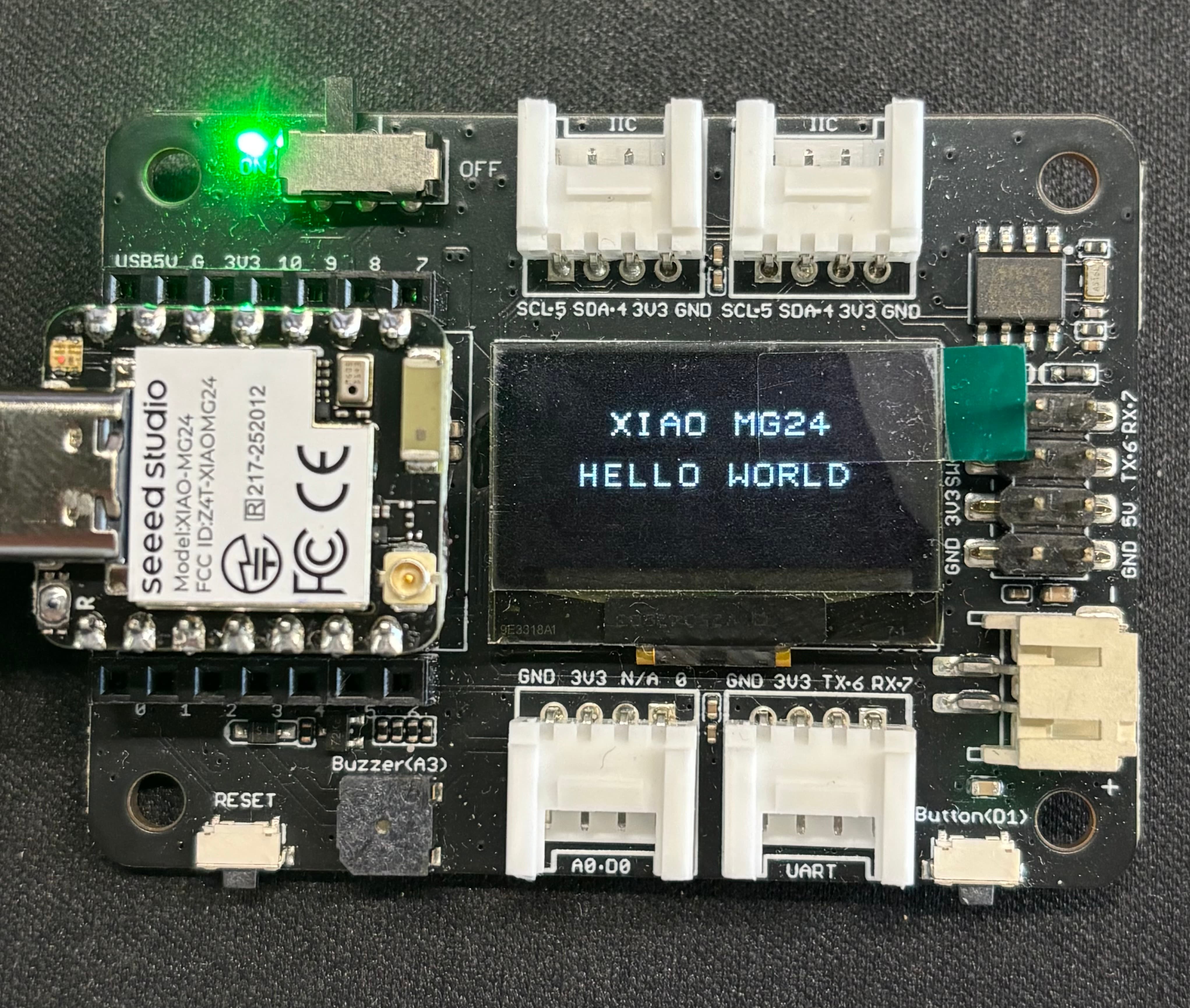
0x3C, an exception is raised; otherwise, a success message is printed. ssd1306_init()Initializes the display hardware.ssd1306_draw_text("XIAO MG24", 30, 2)Draws the string XIAO MG24 starting at column 30, page 2 (≈ row 16).ssd1306_draw_text("HELLO WORLD", 20, 4)Draws the string HELLO WORLD starting at column 20, page 4 (≈ row 32).
Result graph
- Once the program starts running, it will display XIAO MG24 and HELLO WORLD on the screen.
Summary
Congratulations! Having completed the tutorials above, you have acquired the capability for basic development and debugging with XIAO MG24 Sense and MicroPython. We look forward to seeing you create more interesting projects based on these foundational skills
Tech Support & Product Discussion
Thank you for choosing our products! We are here to provide you with different support to ensure that your experience with our products is as smooth as possible. We offer several communication channels to cater to different preferences and needs.