Arduino for Seeed Studio XIAO nRF54L15
This article is developed based on the XIAO nRF54L15 Sense with the Arduino platform.
Acknowledgements
Special thanks to the developer lolren for providing Arduino adaptation support for the nRF54L15 chip. This enables the development and practical application of the XIAO nRF54L15 on the Arduino ecosystem. Gratitude is also extended for his continuous efforts and contributions to the related open-source ecological construction.
Getting Started
Hardware Preparation
Before starting, prepare either the XIAO nRF54L15 or XIAO nRF54L15 Sense hardware.
| Seeed Studio XIAO nRF54L15 | Seeed Studio XIAO nRF54L15 Sense |
|---|---|
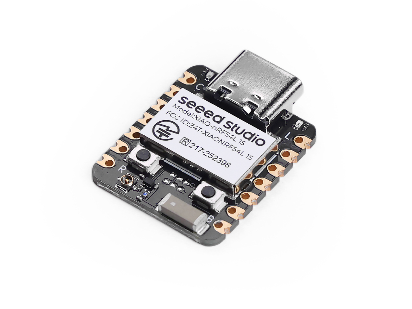 | 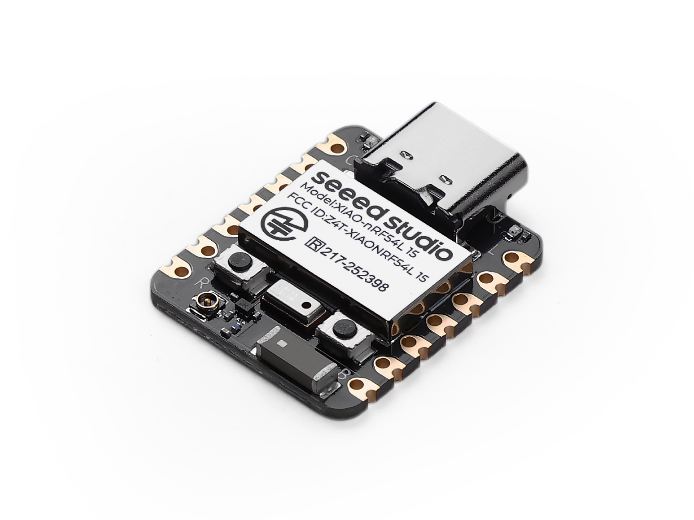 |
Software
If this is your first time using Arduino, we highly recommend you to refer to Getting Started with Arduino.
-
Step 1. Download and Install the stable version of Arduino IDE according to your operating system.
-
Step 2. Add Boards Manager URL
Open File → Preferences
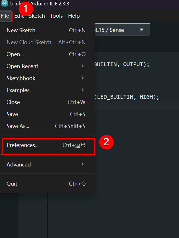
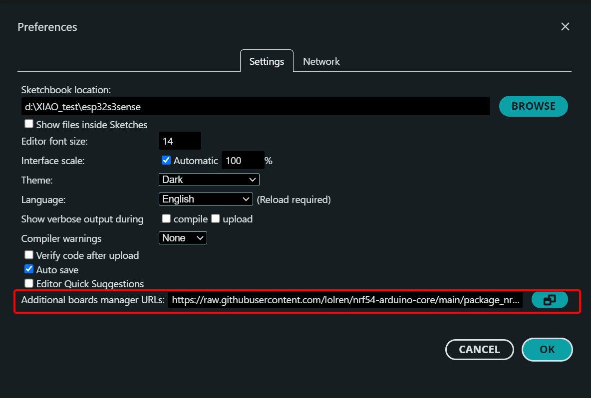
Add the URL for XIAO nRF54L15 support in the Additional Boards Manager URLs field.
https://raw.githubusercontent.com/lolren/nrf54-arduino-core/main/package_nrf54l15clean_index.json
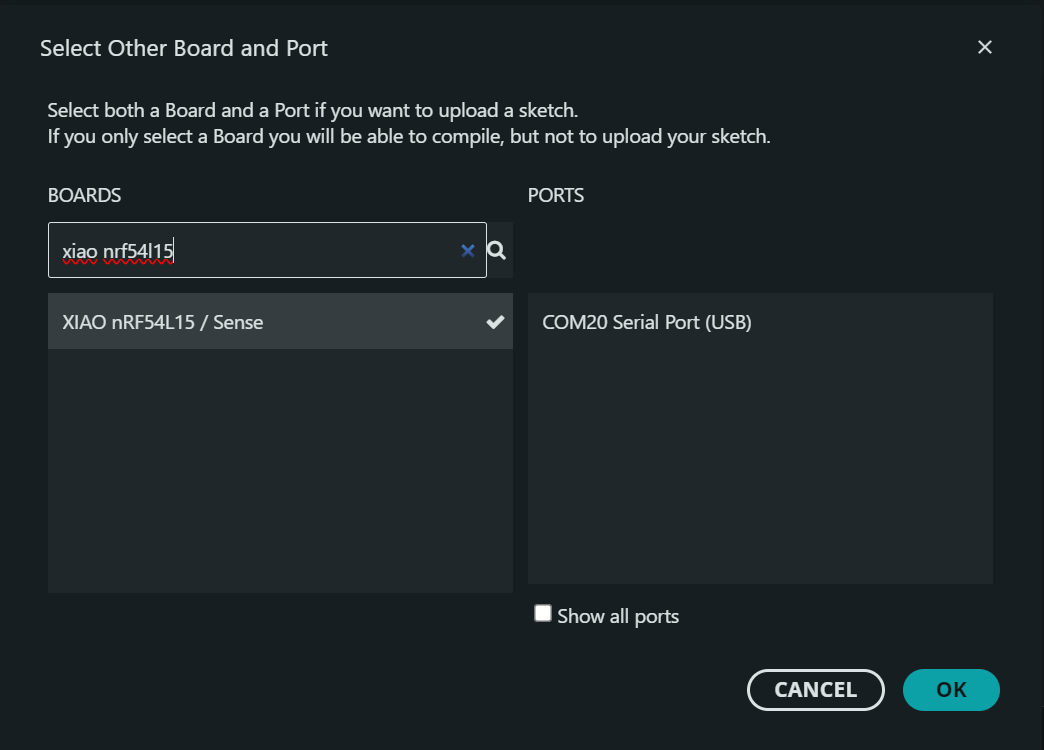
- Step 3. Select XIAO nRF54L15 / Sense and serial port
- Step 4. Upload the program
void setup() {
  pinMode(LED_BUILTIN, OUTPUT);
}

void loop() {
  digitalWrite(LED_BUILTIN, LOW);
  delay(500);
  digitalWrite(LED_BUILTIN, HIGH);
  delay(500);
}
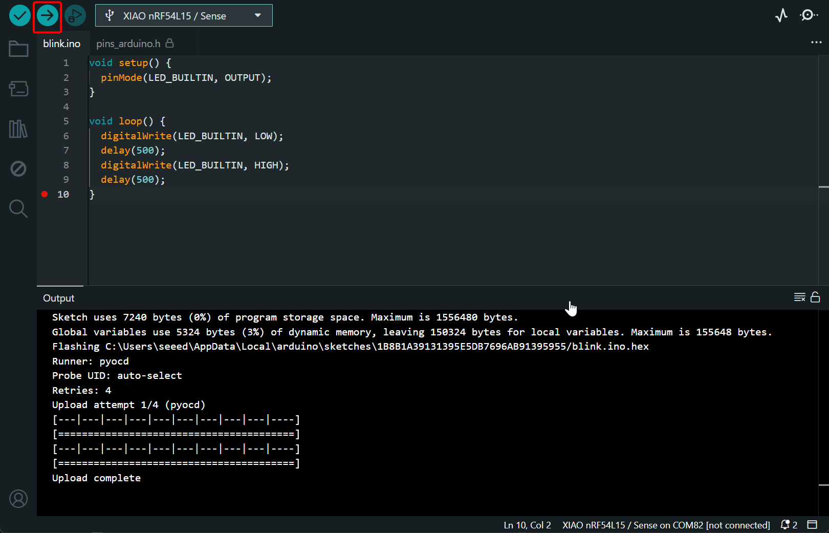
Result:
Digital
Digital pins are MCU interfaces for reading and writing high/low logic levels, which can acquire external data and control peripheral devices. This section illustrates the functions of digital pins by implementing LED on-off control and PWM breathing light effect.
Hardware Preparation
You need to prepare the XIAO nRF54L15 Sense and Grove devices.
| Seeed Studio XIAO nRF54L15 Sense | Seeed Studio Grove Base for XIAO | Grove – Chainable RGB LED |
|---|---|---|
|  |  |
Software
In the lolren repository, pins D0 to D10 of the XIAO nRF54L15 are redefined as PIN_D0 to PIN_D10.
void setup() {
  pinMode(PIN_D0, OUTPUT);
}

void loop() {
  digitalWrite(PIN_D0, LOW);
  delay(500);
  digitalWrite(PIN_D0, HIGH);
  delay(500);

  for (int i = 0; i <= 255; i++) {
      analogWrite(PIN_D0, i);  // The duty cycle increases gradually.
      delay(5);
    }

  for (int i = 255; i >= 0; i--) {
        analogWrite(PIN_D0, i);  // The duty cycle decreases gradually.
        delay(5);
    }
}
Result
Connect the Grove – Chainable RGB LED to Pin 0 of the Seeed Studio Grove Base for XIAO. The Grove – Chainable RGB LED will present flashing and gradual dimming breathing effects.
UART
UART is an asynchronous half-duplex communication protocol, commonly used for device debugging, log output and data transmission. The XIAO nRF54L15 provides one set of UART pins. This section demonstrates the usage of UART through serial data printing.
Hardware Preparation
You need to prepare the XIAO nRF54L15 and CH340 device.
| Seeed Studio XIAO nRF54L15 Sense | CH340G USB to Serial (TTL) Module&Adapter |
|---|---|
|  |
Software
On the XIAO nRF54L15, D6 and D7 correspond to the TX and RX pins respectively. In the pin redefinition file from lolren, D6 and D7 are defined as PIN_SERIAL1_RX and PIN_SERIAL1_TX. The available serial ports for use are Serial1 or Serial2.
If you are not familiar with the pin distribution of the XIAO nRF54L15, click XIAO nRF54L15 Pin List to check.
Do not use PIN_SERIAL1_RX and PIN_SERIAL1_TX for Serial (USB serial port).
This will disrupt the default download and debugging channels, and may result in program flashing failure (SWD/CDC malfunction).
#define RX_PIN PIN_SERIAL1_RX
#define TX_PIN PIN_SERIAL1_TX
#define BAUD 115200

void setup() {
    // Set RX and TX pins
    Serial1.setPins(RX_PIN, TX_PIN);

    // Initialize baud rate and communication configuration
    Serial1.begin(BAUD, SERIAL_8N1);
}

void loop() {
    Serial1.print("Hello XIAO nRF54L15!\n");
    delay(1000);
}
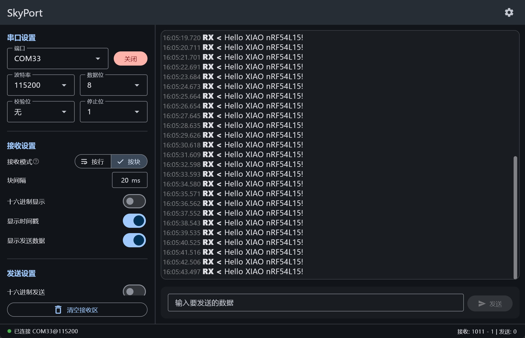
Result
Wiring
| XIAO nRF54L15 | CH340G USB to Serial (TTL) Module&Adapter |
|---|---|
| RX | TX |
| TX | RX |
| GND | GND |
| VBUS | 5V |
Open any serial monitor tool, set the baud rate to 115200, and you can observe the output data.
Analog
Analog pins are used to read continuous voltage signals through the ADC. They can be connected to various sensors such as potentiometers, photoresistors, thermistors for temperature detection, analog grayscale sensors and infrared sensors. This section demonstrates the functions of analog pins by reading the adjustment value of a potentiometer knob.
Hardware Preparation
You need to prepare the XIAO nRF54L15 Sense and Grove devices.
| Seeed Studio XIAO nRF54L15 Sense | Grove-Rotary Angle Sensor | Seeed Studio Grove Base for XIAO |
|---|---|---|
|  |  |
Software
There are four groups of analog pins on the XIAO nRF54L15, namely A0 to A3. In the pin redefinition provided by lolren, these pins are defined as PIN_A0 to PIN_A3.
If you are not familiar with the pin distribution of the XIAO nRF54L15, click XIAO nRF54L15 Pin List to check.
const int analogPin = PIN_A0;

void setup() {
  Serial.begin(115200);
  analogReadResolution(12);
}

void loop() {
  int analogValue = analogRead(analogPin);

  // Assume reference voltage is 3.3V
  int voltage_mv = analogValue * 3300 / 4095;

  Serial.printf("ADC value = %d\n", analogValue);
  Serial.printf("Voltage = %d mV\n", voltage_mv);

  delay(1000);
}
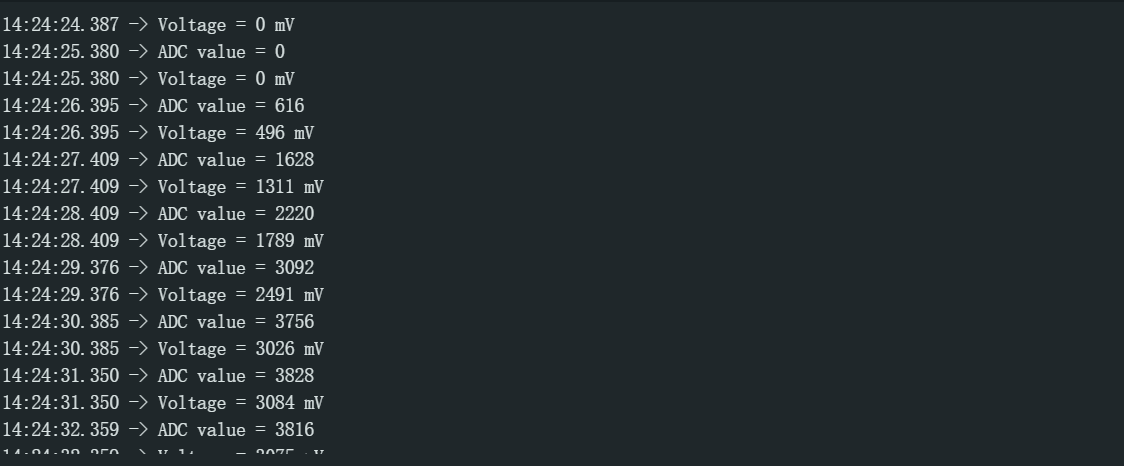
Result
Connect the Grove-Rotary Angle Sensor to the Seeed Studio Grove Base for XIAO.
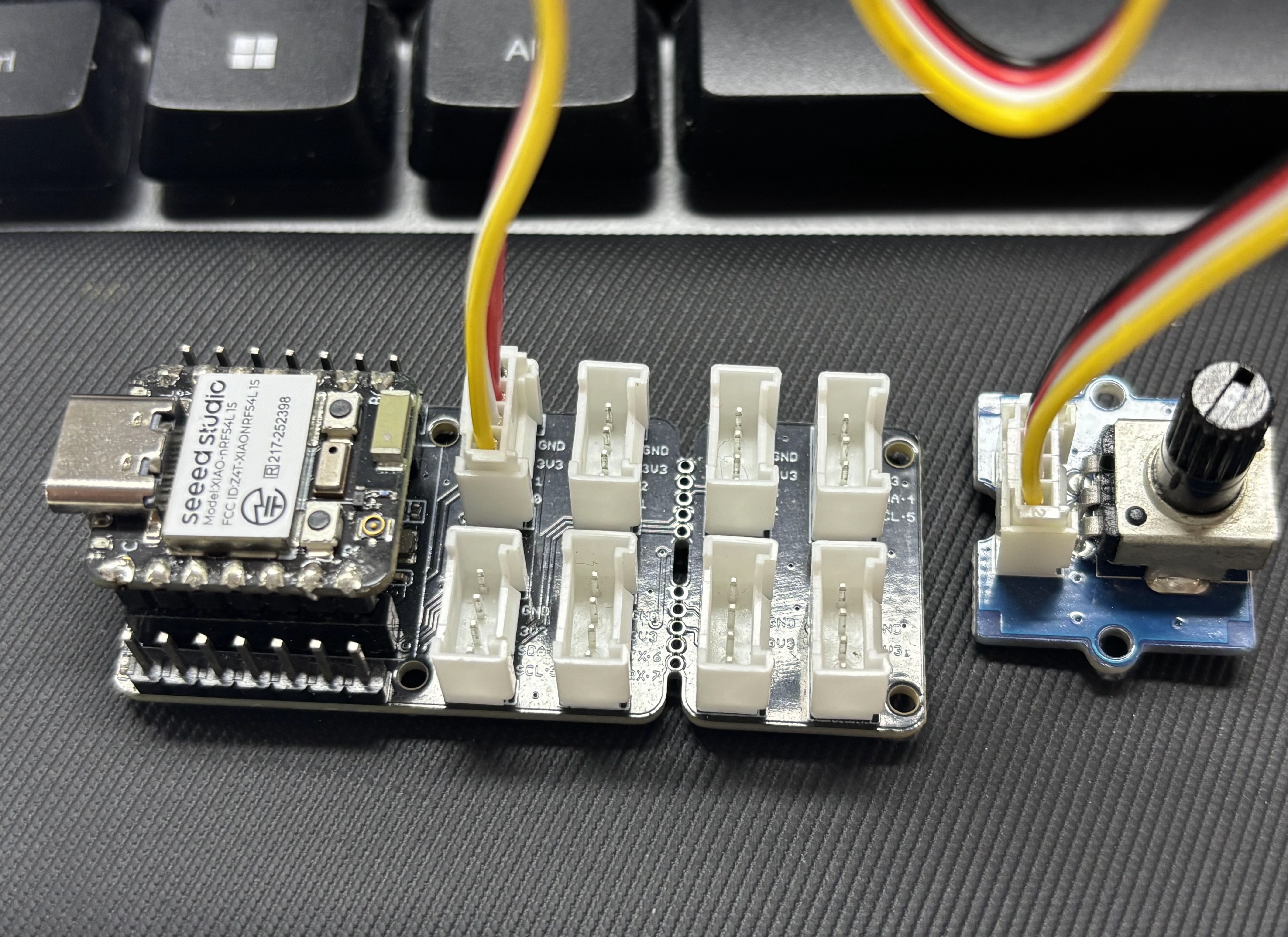
Rotate the knob, and the Arduino Serial Monitor will print the ADC reading value and the converted analog voltage.
I2C
I2C is a synchronous serial communication protocol that enables multi-device communication between master and slave devices via the SCL clock line and SDA data line. The XIAO nRF54L15 / Sense provides two sets of I2C interfaces. This section demonstrates the functions of I2C by controlling the OLED display on the Expansion Board Base for XIAO.
Hardware Preparation
You need to prepare the XIAO nRF54L15 Sense and devices with I2C interfaces.
| Seeed Studio XIAO nRF54L15 Sense | Seeed Studio Expansion Board Base for XIAO |
|---|---|
|  |
Software
On the XIAO nRF54L15, D4 and D5 serve as the SCL and SDA pins respectively. In the lolren framework, pin D4 is redefined as PIN_WIRE_SCL, and pin D5 is redefined as PIN_WIRE_SDA.
If you are not familiar with the pin distribution of the XIAO nRF54L15, click XIAO nRF54L15 Pin List to check.
#include <U8x8lib.h>
#include <Wire.h>

#define SCL PIN_WIRE_SCL
#define SDA PIN_WIRE_SDA

U8X8_SSD1306_128X64_NONAME_HW_I2C u8x8(/* clock=*/ SCL, /* data=*/ SDA, /* reset=*/ U8X8_PIN_NONE);   // OLEDs without Reset of the Display

void setup(void) {
  u8x8.begin();
  u8x8.setFlipMode(0);
}

void loop(void) {
  u8x8.setFont(u8x8_font_chroma48medium8_r);

  u8x8.setCursor(2, 10);
  u8x8.print("Hello World!");
  u8x8.setCursor(1, 28);
  u8x8.print("XIAO nRF54L15!");
}
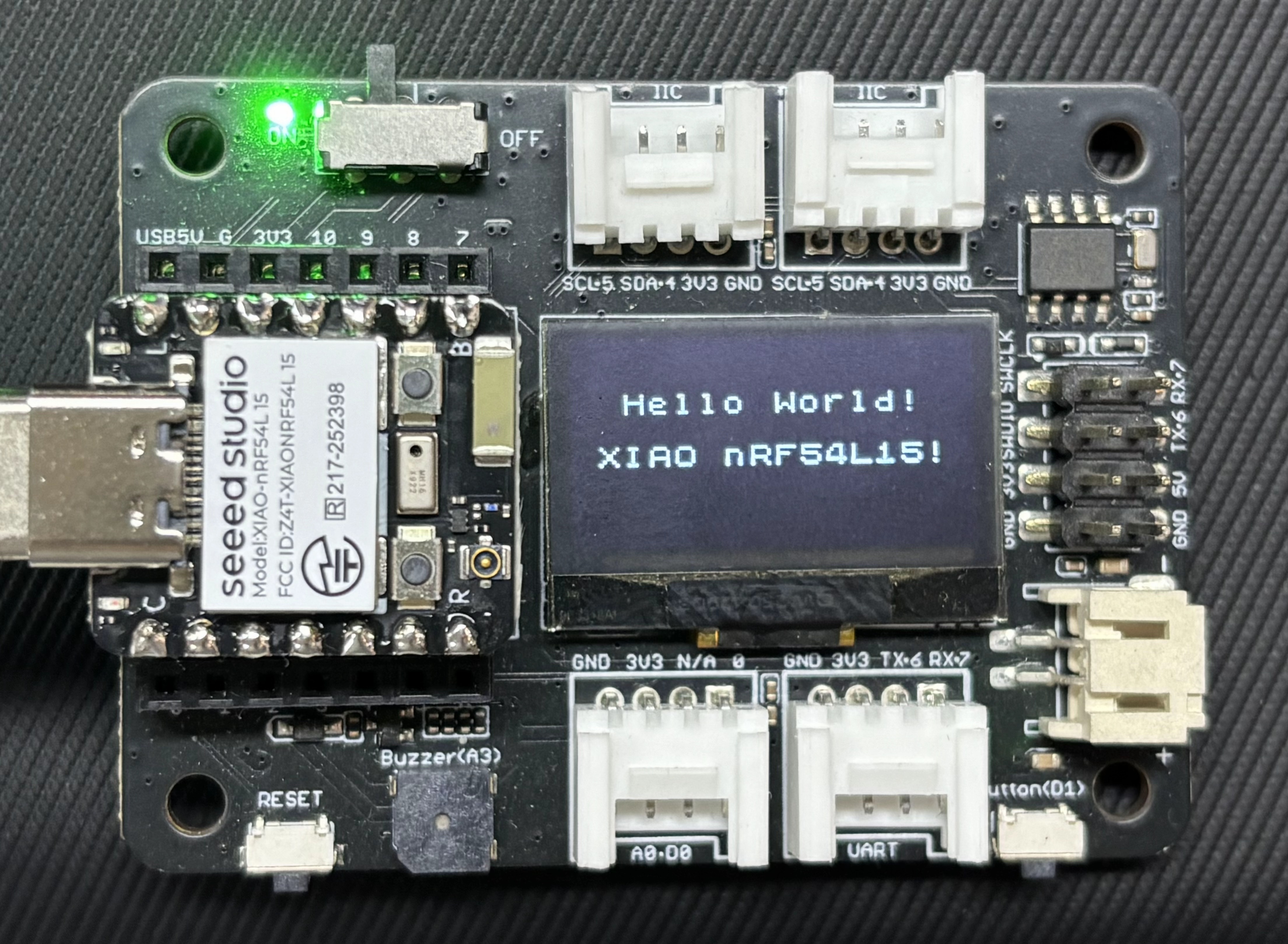
Result
After uploading the program, the phrases "Hello World!" and "XIAO nRF54L15!" will be displayed on the Expansion Board Base for XIAO.
SPI
SPI is a synchronous serial and full-duplex communication protocol. It generally uses four wires — SCK clock, MOSI, MISO and CS — to achieve high-speed data transmission between master and slave devices. Compared with I2C, SPI features a higher transmission rate, lower latency and simpler and more straightforward communication. However, it requires more pins, and each slave device usually occupies an independent chip select line. It is commonly used to connect high-speed peripherals such as Flash memory, SD cards, LCD/OLED displays, ADC/DAC modules and high-speed sensors. This section demonstrates the usage of SPI by connecting an e-paper display.
Hardware Preparation
You need to prepare a XIAO nRF54L15 and a device that supports SPI communication.
| Seeed Studio XIAO nRF54L15 Sense | ePaper Driver Board for Seeed Studio XIAO | 2.9" Monochrome eInk |
|---|---|---|
|  |  |
Software
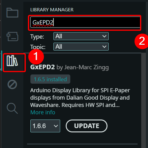
- Install the GxEPD2 library
Modify and macro define the SPI pins according to Lolren's pin redefinition file.
#include <Arduino.h>
#include <SPI.h>
#include <GxEPD2_BW.h>
#include <Fonts/FreeMonoBold9pt7b.h>
#include <Fonts/FreeMonoBold12pt7b.h>

// -------- Pin Definitions (from pins_arduino.h) --------
// PIN_D0=RST, PIN_D1=CS, PIN_D3=DC, PIN_D5=BUSY
// SPI: SCK=PIN_D8, MISO=PIN_D9, MOSI=PIN_D10 (macros are already defined)
#define EPD_RST  PIN_D0   // 0
#define EPD_CS   PIN_D1   // 1
#define EPD_DC   PIN_D3   // 3
#define EPD_BUSY PIN_D2   // 5

// -------- 029BN-T94-D2 Driver --------
GxEPD2_BW<GxEPD2_290_T94_V2, GxEPD2_290_T94_V2::HEIGHT> display(
  GxEPD2_290_T94_V2(EPD_CS, EPD_DC, EPD_RST, EPD_BUSY)
);

const char* LINE1 = "Hello XIAO nRF54L15";

void setup() {
  Serial.begin(115200);
  delay(2000);
  Serial.println("=== EPaper Start ===");

  // Close serial port to avoid TX(D1) interfering with CS(D1)
  delay(100);
  Serial.end();

  // Directly specify using macros, fully consistent with pins_arduino.h
  SPI.setPins(PIN_SPI_SCK, PIN_SPI_MISO, PIN_SPI_MOSI, -1);
  SPI.begin();

  // Pass 0 to disable GxEPD2 internal serial debug output
  display.init(0);
  display.setRotation(1);  // Landscape 296×128
  display.setTextColor(GxEPD_BLACK);
  display.setFullWindow();

  display.firstPage();
  do {
    display.fillScreen(GxEPD_WHITE);

    // ---- LINE1: Large font, upper half ----
    display.setFont(&FreeMonoBold12pt7b);
    int16_t tbx, tby;
    uint16_t tbw, tbh;
    display.getTextBounds(LINE1, 0, 0, &tbx, &tby, &tbw, &tbh);
    uint16_t x1 = (display.width()  - tbw) / 2 - tbx;
    uint16_t y1 = display.height() / 2 - 4;
    display.setCursor(x1, y1);
    display.print(LINE1);

  } while (display.nextPage());

  display.hibernate();

  // Reopen serial port for confirmation after screen refresh
  Serial.begin(115200);
  delay(100);
  Serial.println("=== Done ===");
}

void loop() {
  delay(1000000);
}
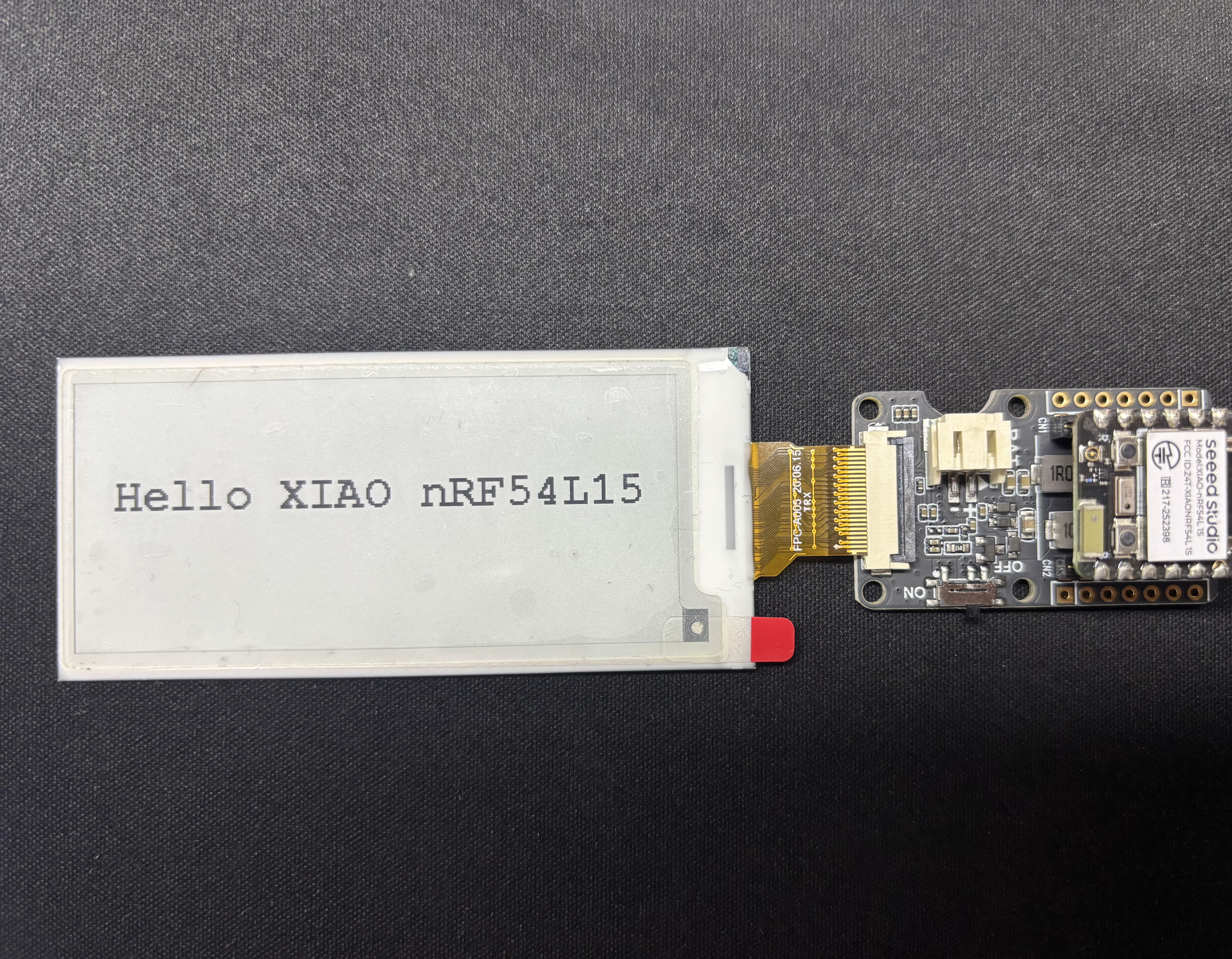
Result
After uploading the program, Hello XIAO nRF54L15 will be displayed on the e-paper screen.
FAQ
-
Q1: When uploading the program, a prompt shows that there is no path for py.
-
A: C:\Users\yourname\AppData\Local\Arduino15\packages\nrf54l15clean\hardware\nrf54l15clean\0.6.27\platform.txt.
- Change
tools.python3.cmd.windows=pytotools.python3.cmd.windows=python. - Change
tools.python3.args.windows=-3totools.python3.args.windows=.
- Change
Tech Support & Product Discussion
Thank you for choosing our products! We are here to provide you with different support to ensure that your experience with our products is as smooth as possible. We offer several communication channels to cater to different preferences and needs.