Usage of Seeed Studio XIAO nRF54L15 Sense built-in Sensor
The following sample code is designed for PlatformIO, but it is also compatible with the nRF Connect SDK.
Based on VS Code, if you want to use the following case on the nRF Connect SDK, please refer to the provided connection, add the app.overlay file and modify the contents in prj.conf
XIAO nRF54L15 Sense IMU
6-Axis IMU (Inertial Measurement Unit) Sensors like the LSM6DS3TR-C integrate accelerometers and gyroscopes to measure the motion and orientation of an object in three-dimensional space. Specifically, the LSM6DS3TR-C has the following features:
Accelerometer function:
- Measures the acceleration of an object along the X, Y, and Z axes. It is able to sense object motion (e.g., rest, acceleration, deceleration) and tilt changes (e.g., angle of the object).
- It can be used to detect gait, position changes, vibrations, etc.
Gyroscope function (Gyroscope):
- Measures the angular velocity of an object around the X, Y, and Z axes, i.e., the rotation of the object.
- Can be used to detect rotation, rate of rotation, and change in direction.
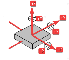
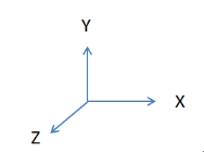
- The X-axis angle ( Roll ) is the angle in the direction of rotation around the X-axis.
- The Y-axis angle ( Pitch ) is the angle in the direction of rotation around the Y-axis.
- The Z-axis angle ( Yaw ) is the angle in the direction of rotation around the Z-axis.
IMU Driver
To simplify your development experience and ensure a quick start with this IMU program, we've leveraged the PlatformIO platform for writing the necessary driver code. PlatformIO offers a comprehensive and efficient environment for embedded development, making it an ideal choice for the XIAO nRF54L15 Sense.
Before proceeding, please ensure that your development environment is correctly set up. If you haven't yet added the Seeed Studio XIAO nRF54L15 development board to your PlatformIO configuration, kindly refer to this link for detailed instructions on how to configure it. This crucial step will enable PlatformIO to properly recognize and compile code for your board.
Once your environment is ready, the IMU driver will allow you to read raw sensor data from the LSM6DS3TR-C. This data includes:
-
Accelerometer raw values (accel raw): Representing the acceleration along the X, Y, and Z axes.
-
Gyroscope raw values (gyro raw): Indicating the angular velocity around the X, Y, and Z axes.
-
Trigger count (trig_cnt): A counter that increments with each new data sample.
Download the repository to C:\Users\xxx\.platformio\platforms and open the examples\zephyr-imufolder in VS Code. Then click on main.c, and you will see the following code:
#include <zephyr/kernel.h>
#include <zephyr/device.h>
#include <zephyr/drivers/sensor.h>
#include <zephyr/logging/log.h>

LOG_MODULE_REGISTER(zephyr_imu, LOG_LEVEL_INF);

static inline float out_ev(struct sensor_value *val)
{
	return (val->val1 + (float)val->val2 / 1000000);
}

static void fetch_and_display(const struct device *dev)
{
	struct sensor_value x, y, z;
	static int trig_cnt;

	trig_cnt++;

	/* lsm6dsl accel */
	sensor_sample_fetch_chan(dev, SENSOR_CHAN_ACCEL_XYZ);
	sensor_channel_get(dev, SENSOR_CHAN_ACCEL_X, &x);
	sensor_channel_get(dev, SENSOR_CHAN_ACCEL_Y, &y);
	sensor_channel_get(dev, SENSOR_CHAN_ACCEL_Z, &z);

	LOG_INF("accel x:%f m/s^2 y:%f m/s^2 z:%f m/s^2",
			(double)out_ev(&x), (double)out_ev(&y), (double)out_ev(&z));

	/* lsm6dsl gyro */
	sensor_sample_fetch_chan(dev, SENSOR_CHAN_GYRO_XYZ);
	sensor_channel_get(dev, SENSOR_CHAN_GYRO_X, &x);
	sensor_channel_get(dev, SENSOR_CHAN_GYRO_Y, &y);
	sensor_channel_get(dev, SENSOR_CHAN_GYRO_Z, &z);

	LOG_INF("gyro x:%f rad/s y:%f rad/s z:%f rad/s",
			(double)out_ev(&x), (double)out_ev(&y), (double)out_ev(&z));

	LOG_INF("trig_cnt:%d", trig_cnt);
}

static int set_sampling_freq(const struct device *dev)
{
	int ret = 0;
	struct sensor_value odr_attr;

	/* set accel/gyro sampling frequency to 12.5 Hz */
	odr_attr.val1 = 12.5;
	odr_attr.val2 = 0;

	ret = sensor_attr_set(dev, SENSOR_CHAN_ACCEL_XYZ,
			SENSOR_ATTR_SAMPLING_FREQUENCY, &odr_attr);
	if (ret != 0) {
		LOG_ERR("Cannot set sampling frequency for accelerometer.");
		return ret;
	}

	ret = sensor_attr_set(dev, SENSOR_CHAN_GYRO_XYZ,
			SENSOR_ATTR_SAMPLING_FREQUENCY, &odr_attr);
	if (ret != 0) {
		LOG_ERR("Cannot set sampling frequency for gyro.");
		return ret;
	}

	return 0;
}

#ifdef CONFIG_LSM6DSL_TRIGGER
static void trigger_handler(const struct device *dev,
			    const struct sensor_trigger *trig)
{
	fetch_and_display(dev);
}

static void test_trigger_mode(const struct device *dev)
{
	struct sensor_trigger trig;

	if (set_sampling_freq(dev) != 0) {
		return;
	}

	trig.type = SENSOR_TRIG_DATA_READY;
	trig.chan = SENSOR_CHAN_ACCEL_XYZ;

	if (sensor_trigger_set(dev, &trig, trigger_handler) != 0) {
		LOG_ERR("Could not set sensor type and channel");
		return;
	}
}

#else
static void test_polling_mode(const struct device *dev)
{
	if (set_sampling_freq(dev) != 0) {
		return;
	}

	while (1) {
		fetch_and_display(dev);
		k_sleep(K_MSEC(1000));
	}
}
#endif

int main(void)
{
	const struct device *const dev = DEVICE_DT_GET(DT_ALIAS(imu0));

	if (!device_is_ready(dev)) {
		LOG_ERR("%s: device not ready.", dev->name);
		return 0;
	}

#ifdef CONFIG_LSM6DSL_TRIGGER
	LOG_INF("Testing LSM6DSL sensor in trigger mode.");
	test_trigger_mode(dev);
#else
	LOG_INF("Testing LSM6DSL sensor in polling mode.");
	test_polling_mode(dev);
#endif
	return 0;
}
Now, connect your XIAO nRF54L15 to your computer via USB. In VS Code:
-
Build: Click the "Build" icon (checkmark) in the PlatformIO toolbar at the bottom of VS Code, or use the PlatformIO sidebar: PROJECT TASKS -> your_project_name -> General -> Build.
-
Upload: After a successful build, click the "Upload" icon (right arrow) in the PlatformIO toolbar, or use the PlatformIO sidebar: PROJECT TASKS -> your_project_name -> General -> Upload.
After a successful upload, you should see output similar to the example below in the PlatformIO Device Monitor(PROJECT TASKS -> your_project_name -> General -> Monitor). This serial output shows real-time accelerometer and gyroscope readings, providing key insights into the motion and orientation of your device.

Real-time IMU Data Output from PlatformIO Device Monitor, displaying raw accelerometer and gyroscope readings.
This raw data forms the basis for various applications, from simple motion detection to complex orientation tracking, by applying appropriate algorithms (e.g., filtering, sensor fusion).
XIAO nRF54L15 Sense MIC
The MSM261DGT006 is a Digital Microphone (DMIC) that outputs Pulse Density Modulation (PDM) data, making it suitable for direct digital interfacing with microcontrollers like the XIAO nRF54L15 Sense. Our DMIC driver is specifically designed to handle this PDM output, convert it into usable audio samples, and process it for various applications.
The driver initiates the microphone, sets the appropriate sampling rate (e.g., 16000 Hz for standard audio), and configures the PDM clock frequency. It then continuously reads sample buffers from the microphone, allowing for real-time audio capture.
The output from the DMIC driver, when viewed in the PlatformIO Device Monitor, provides crucial information about the microphone's operation and the incoming audio data. Key messages you will observe include:
-
DMIC sample=:Indicates the start of the DMIC sampling process. -
PCM output rate:16000, channels: 1: Confirms the audio output settings, typically a sample rate of 16 kHz and a single channel (mono) audio. -
dmic_nrf_pdm:PDM clock frequency: 1280000, actual PCM rate: 16000: Shows the internal PDM clock frequency and the resulting PCM audio sample rate. -
got buffer 0x... of 3200 bytes:Confirms that the driver successfully received a buffer of audio data from the microphone. The hexadecimal address (e.g., 0x20004C8) and size in bytes (e.g., 3200 bytes) are shown. These buffers contain the raw audio samples that can then be processed or analyzed. -
dmix_sample: Exiting:Indicates that the DMIC sampling process has been stopped.
Below is an example of the typical output you can expect to see in the PlatformIO Device Monitor when the DMIC driver is running, illustrating the successful capture and buffering of audio data.
DMIC Driver
This raw audio data, once captured, can be used for a wide range of applications, including voice commands, sound event detection, environmental noise monitoring, and more complex audio processing tasks.
The following code example demonstrates how to record audio using the push button on the XIAO nRF54L15 board and save the recorded WAV file on a computer.
#include <zephyr/kernel.h>
#include <zephyr/device.h>
#include <zephyr/drivers/gpio.h>
#include <zephyr/audio/dmic.h>
#include <zephyr/sys/util.h>
#include <zephyr/logging/log.h>
#include <zephyr/drivers/uart.h>

LOG_MODULE_REGISTER(mic_capture_sample, LOG_LEVEL_INF);

#define RECORD_TIME_S  10                // Recording duration (seconds)
#define SAMPLE_RATE_HZ 16000            // Sample rate (Hz)
#define SAMPLE_BIT_WIDTH 16             // Sample bit width (bits)
#define BYTES_PER_SAMPLE (SAMPLE_BIT_WIDTH / 8) // Bytes per sample

#define READ_TIMEOUT_MS 1000            // DMIC read timeout (ms)
#define CHUNK_DURATION_MS 100           // Duration of each chunk (ms)
#define CHUNK_SIZE_BYTES  (BYTES_PER_SAMPLE * (SAMPLE_RATE_HZ * CHUNK_DURATION_MS) / 1000) // Chunk size (bytes)
#define CHUNK_COUNT       8             // Number of blocks in memory pool
#define TOTAL_CHUNKS      (RECORD_TIME_S * 1000 / CHUNK_DURATION_MS) // Total number of chunks

static const struct device *const dmic_dev = DEVICE_DT_GET(DT_ALIAS(dmic20)); // DMIC device handle
static const struct gpio_dt_spec led = GPIO_DT_SPEC_GET(DT_ALIAS(led0), gpios); // LED device descriptor
static const struct gpio_dt_spec button = GPIO_DT_SPEC_GET(DT_ALIAS(sw0), gpios); // Button device descriptor
static const struct device *const console_dev = DEVICE_DT_GET(DT_CHOSEN(zephyr_console)); // Console UART device

K_MEM_SLAB_DEFINE_STATIC(mem_slab, CHUNK_SIZE_BYTES, CHUNK_COUNT, 4); // Audio data memory pool
K_MSGQ_DEFINE(audio_msgq, sizeof(void *), CHUNK_COUNT, 4);

static K_SEM_DEFINE(tx_done_sem, 0, 1); // Button semaphore
static K_SEM_DEFINE(button_sem, 0, 1); // UART TX done semaphore

static const uint8_t packet_start[] = {0xAA, 0x55, 'S', 'T', 'A', 'R', 'T'}; // Packet start marker
static const uint8_t packet_end[] = {0xAA, 0x55, 'E', 'N', 'D'};             // Packet end marker

static struct gpio_callback button_cb_data;

/**
 * @brief UART callback function
 *
 * @param dev UART device pointer
 * @param evt UART event
 * @param user_data User data (unused)
 */
static void uart_tx_callback(const struct device *dev, struct uart_event *evt, void *user_data)
{
    if (evt->type == UART_TX_DONE) {
        k_sem_give(&tx_done_sem);
    }
}

/**
 * @brief Button interrupt callback function
 *
 * @param dev Button device pointer
 * @param cb  Callback structure pointer
 * @param pins Triggered pins
 */
void button_pressed(const struct device *dev, struct gpio_callback *cb, uint32_t pins)
{
    k_sem_give(&button_sem);
}

/**
 * @brief Send a data packet via UART (polling, for small packets)
 *
 * @param data Data pointer
 * @param len  Data length
 */
static void send_packet_poll(const uint8_t *data, size_t len)
{
    for (size_t i = 0; i < len; i++) {
        uart_poll_out(console_dev, data[i]);
    }
}

/**
 * @brief UART writer thread function
 *
 * This thread continuously reads audio data from the message queue and sends it via UART.
 * It waits for the semaphore to signal that the previous transmission is done before sending the next chunk.
 */
void uart_writer_thread(void *p1, void *p2, void *p3)
{
    uart_callback_set(console_dev, uart_tx_callback, NULL);

    while (true) {
        void *buffer;
        k_msgq_get(&audio_msgq, &buffer, K_FOREVER);

        if (buffer == NULL) {
            send_packet_poll(packet_end, sizeof(packet_end));
            continue;
        }

        uart_tx(console_dev, buffer, CHUNK_SIZE_BYTES, SYS_FOREVER_US);
        k_sem_take(&tx_done_sem, K_FOREVER);

        k_mem_slab_free(&mem_slab, buffer);
    }
}


K_THREAD_DEFINE(uart_writer_tid, 2048, uart_writer_thread, NULL, NULL, NULL,
                K_PRIO_COOP(7), 0, 0);

static struct pcm_stream_cfg stream_cfg = {
    .pcm_rate = SAMPLE_RATE_HZ,
    .pcm_width = SAMPLE_BIT_WIDTH,
    .block_size = CHUNK_SIZE_BYTES,
    .mem_slab = &mem_slab,
}; // PCM stream configuration

static struct dmic_cfg dmic_config = {
    .io = {
        .min_pdm_clk_freq = 1000000,
        .max_pdm_clk_freq = 3500000,
        .min_pdm_clk_dc = 40,
        .max_pdm_clk_dc = 60,
    },
    .streams = &stream_cfg,
    .channel = {
        .req_num_streams = 1,
        .req_num_chan = 1,
    },
}; // DMIC configuration

/**
 * @brief Record audio from DMIC and stream it via UART
 *
 * @return 0 on success, negative error code on failure
 */
static int record_and_stream_audio(void)
{
    int ret;
    void *buffer;
    uint32_t size;

    k_msgq_purge(&audio_msgq);

    ret = dmic_configure(dmic_dev, &dmic_config);
    if (ret < 0) {
        LOG_ERR("Failed to configure DMIC: %d", ret);
        return ret;
    }

    ret = dmic_trigger(dmic_dev, DMIC_TRIGGER_START);
    if (ret < 0) {
        LOG_ERR("Failed to start DMIC: %d", ret);
        return ret;
    }

    ret = dmic_read(dmic_dev, 0, &buffer, &size, READ_TIMEOUT_MS);
    if (ret < 0) {
        LOG_WRN("Failed to read discard chunk: %d", ret);
    } else {
        k_mem_slab_free(&mem_slab, buffer);
    }

    send_packet_poll(packet_start, sizeof(packet_start));

    for (int i = 0; i < TOTAL_CHUNKS; i++) {
        ret = dmic_read(dmic_dev, 0, &buffer, &size, READ_TIMEOUT_MS);
        if (ret < 0) {
            LOG_ERR("Failed to read from DMIC: %d", ret);
            break;
        }

        ret = k_msgq_put(&audio_msgq, &buffer, K_MSEC(500));
        if (ret != 0) {
            LOG_ERR("Failed to queue buffer. UART thread might be too slow.");
            k_mem_slab_free(&mem_slab, buffer);
            break;
        }
    }

    (void)dmic_trigger(dmic_dev, DMIC_TRIGGER_STOP);

    void *end_marker = NULL;
    k_msgq_put(&audio_msgq, &end_marker, K_NO_WAIT);

    LOG_INF("Audio capture finished and data queued.");
    return 0;
}

/**
 * @brief Main function, initializes peripherals and waits for button to trigger recording in a loop
 *
 * @return Always returns 0
 */
int main(void)
{
    int ret;

 // Check if all required devices are ready
    if (!device_is_ready(dmic_dev) || !device_is_ready(led.port) ||
        !device_is_ready(button.port) || !device_is_ready(console_dev)) {
        LOG_ERR("A required device is not ready.");
        return -ENODEV;
    }

 // Configure DMIC channel mapping
    dmic_config.channel.req_chan_map_lo = dmic_build_channel_map(0, 0, PDM_CHAN_LEFT);

    // Configure LED as output
    ret = gpio_pin_configure_dt(&led, GPIO_OUTPUT_ACTIVE);
    if (ret < 0) { return ret; }

    // Configure button as input and enable interrupt
    ret = gpio_pin_configure_dt(&button, GPIO_INPUT);
    if (ret < 0) { return ret; }
    ret = gpio_pin_interrupt_configure_dt(&button, GPIO_INT_EDGE_TO_ACTIVE);
    if (ret < 0) { return ret; }
    gpio_init_callback(&button_cb_data, button_pressed, BIT(button.pin));
    gpio_add_callback(button.port, &button_cb_data);

    LOG_INF("Zephyr Audio Streamer Ready.");
    LOG_INF("Press button SW0 to start recording...");

    // Main loop, wait for button to trigger recording
    while (1) {
        k_sem_take(&button_sem, K_FOREVER);
        LOG_INF("Button pressed, starting capture...");

        gpio_pin_set_dt(&led, 0);
        record_and_stream_audio();
        gpio_pin_set_dt(&led, 1);

        LOG_INF("\nPress button SW0 to start recording again...");
    }

    return 0;
}
Next, open the terminal in the scripts folder directory and perform the following operations, provided that the program has already been burned.
Setp 1:
python3 -m pip install pyserial
Setp 2:
python record.py -p /dev/cu.usbmodemA0CBDDC33 -o output.wav -b 921600
In this commandpython record.py -p **/dev/cu.usbmodemA0CBDDC33** -o output.wav -b 921600, you need to replace it with your serial port for use.
Setp 3:
- After executing the command, you will be prompted to press the button to record sound.
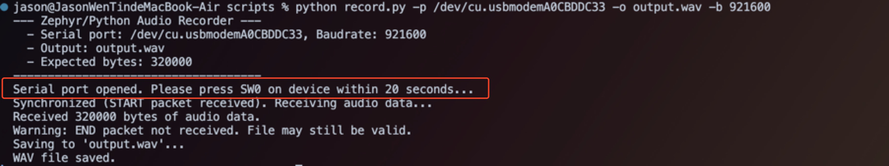
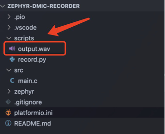
After recording the audio, the file will be saved in scripts
Tech Support & Product Discussion
Thank you for choosing our products! We are here to provide you with different support to ensure that your experience with our products is as smooth as possible. We offer several communication channels to cater to different preferences and needs.