
Getting Started with Seeed Studio XIAO nRF54L15(Sense)
| Seeed Studio XIAO nRF54L15 | Seeed Studio XIAO nRF54L15 Sense |
|---|---|
 |  |
Introduction
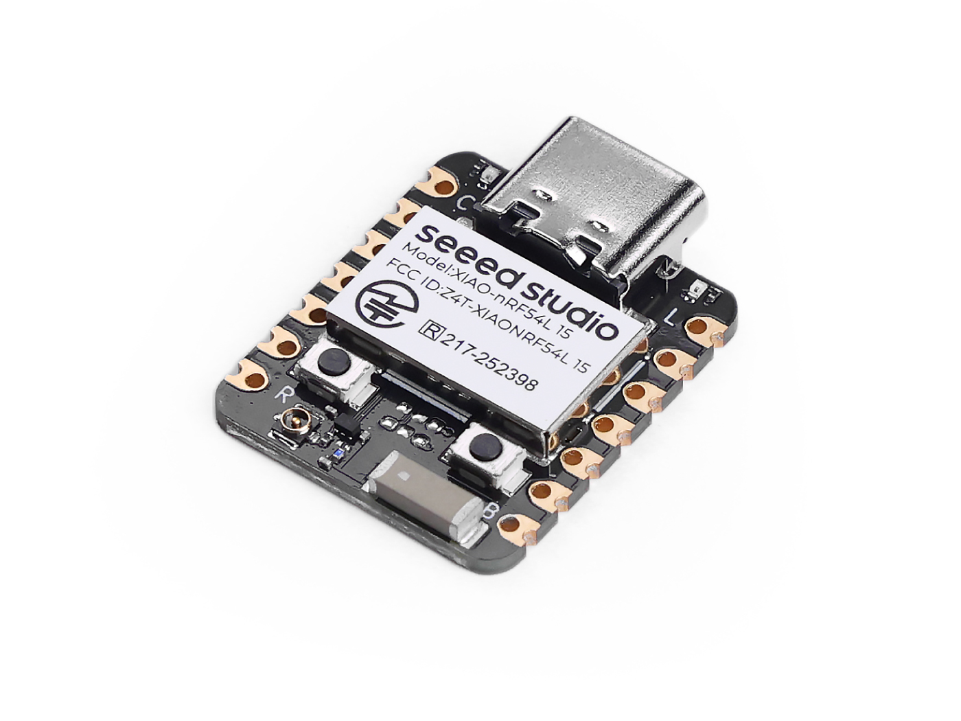
The Seeed Studio XIAO nRF54L15 is a compact, high-performance development board featuring the cutting-edge Nordic nRF54L15 chip. This next-generation SoC integrates an ultra-low-power multi-protocol 2.4 GHz radio with an MCU containing a 128 MHz Arm® Cortex®-M33 processor and a 128 MHz RISC-V coprocessor. It offers scalable memory up to 1.5 MB NVM and 256 KB RAM, and an internal ultra-low-power design that significantly extends battery life. Its powerful radio supports Bluetooth® 6.0 (including Channel Sounding), Matter, Thread, Zigbee, and high throughput 2.4 GHz proprietary modes up to 4 Mbps. The board includes a comprehensive peripheral set, an integrated 128 MHz RISC-V coprocessor, and advanced security features such as TrustZone® isolation and cryptographic engine protection. With built-in Li-ion battery management, the XIAO nRF54L15 is ideal for compact, secure and energy-efficient IoT solutions such as smart wearables, industrial sensors and advanced HMIs.
Specification
| Item | XIAO nRF54L15 | XIAO nRF54L15 Sense |
|---|---|---|
| MCU | Arm Cortex-M33 128 MHz RISC-V coprocessor 128 MHz FLPR | Arm Cortex-M33 128 MHz RISC-V coprocessor 128 MHz FLPR |
| Wireless Connectivity | Bluetooth LE 6.0(include Channel Sounding) | Bluetooth LE 6.0(include Channel Sounding) |
| Memory | NVM 1.5 MB + RAM256 KB | NVM 1.5 MB + RAM256 KB |
| Built-in Sensor | N/A | 6 DOF IMU(LSM6DS3TR-C) Microphone (MSM261DGT006) |
| TX power | +8 dBm | +8 dBm |
| RX sensitivity | -96 dBm | -96 dBm |
| Highlighted peripherals | 14-bit ADC, Global RTC | 14-bit ADC, Global RTC |
| Power | USB Type-C interface power supply | USB Type-C interface power supply |
| Operating temperature | -40 to 105°C | -40 to 105°C |
| Supply voltage range | 3.7 to 5 V | 3.7 to 5 V |
| ESB and 2.4 GHz Proprietary Protocols | up to 4 Mbps | up to 4 Mbps |
| Tamper detectors | YES | YES |
| Bluetooth channel sounding | YES | YES |
Features
- Powerful CPU: 128 MHz Arm® Cortex®-M33 processor with support for DSP instructions and FPU floating-point operations, 32-bit RISC architecture, and integrated 128 MHz RISC-V co-processor.
- Ultra-low Power: Designed for superior ultra-low power consumption, significantly extends battery life and includes advanced power management.
- Multi-Mode Wireless Transmission: Integrated 2.4 GHz multi-protocol wireless transceiver supports Bluetooth Low Energy (including Channel Sounding), 802.15.4-2020, Matter, Thread, Zigbee, and 2.4 GHz proprietary modes (up to 4 Mbps).
- Robust Security: Advanced security features including TrustZone® isolation, tamper detection, and channel leakage protection on the encryption engine side.
- Rich on-chip resources: Scalable memory configurations up to 1.5 MB NVM and 256 KB RAM provide ample storage space.
- Rich Interfaces: Comprehensive peripheral set including the new Global RTC (available in System OFF mode), 14-bit ADC, and high-speed serial interfaces. Built-in lithium battery management.
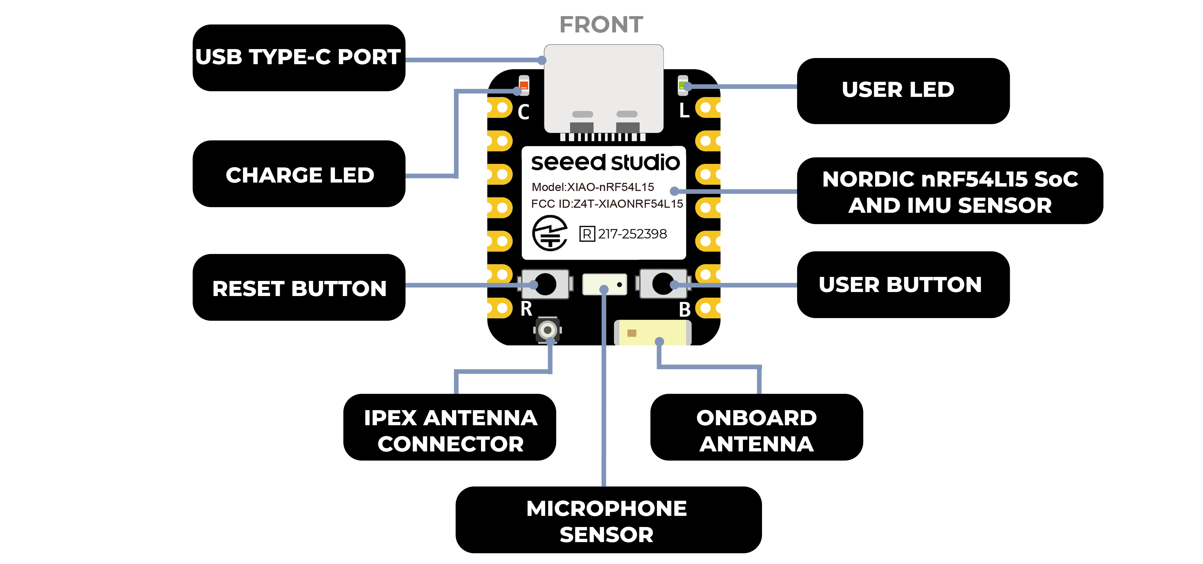
Hardware Overview
- XIAO nRF54L15
- XIAO nRF54L15 Sense
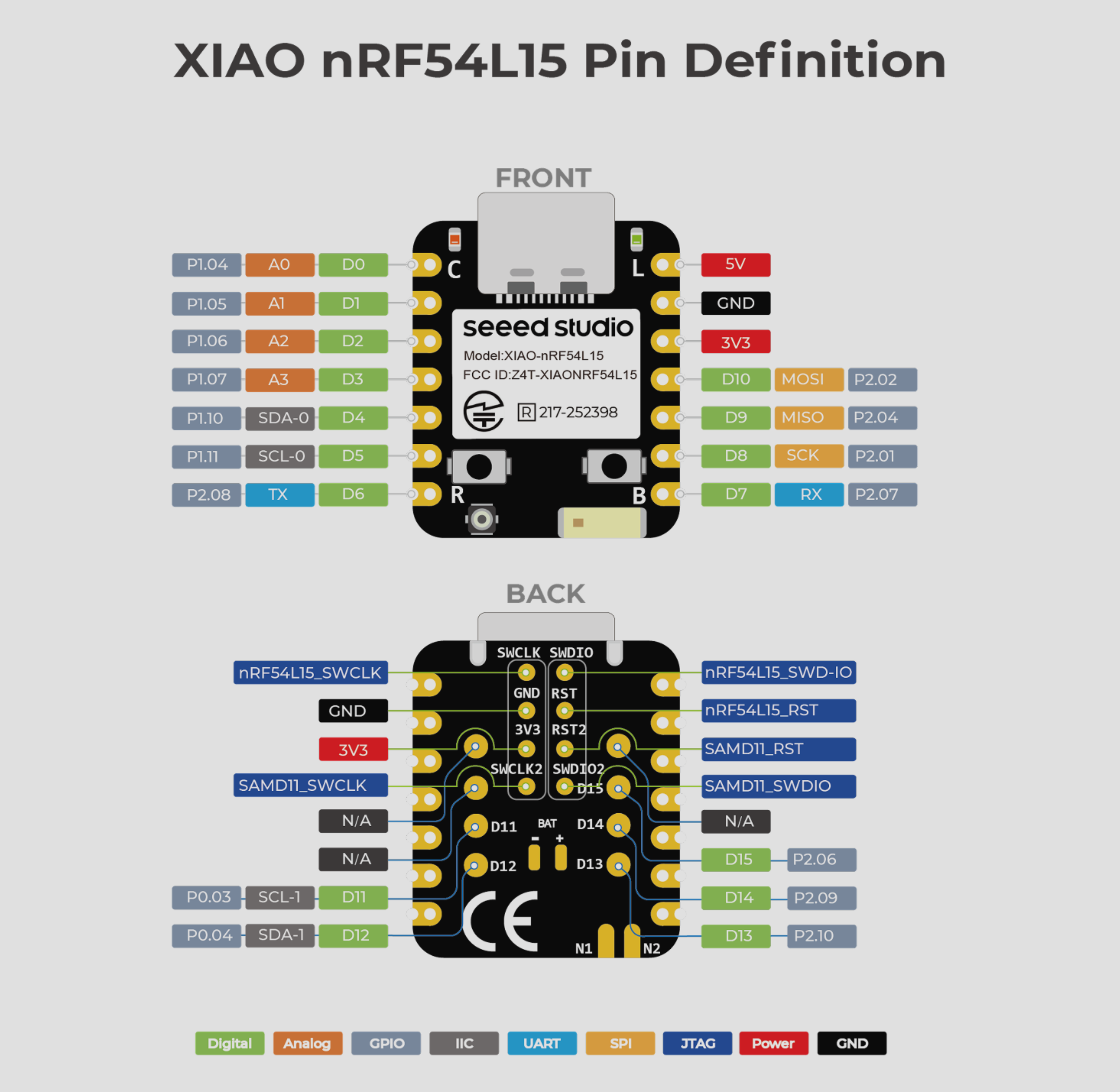
| XIAO nRF54L15 front indication diagram |
|---|
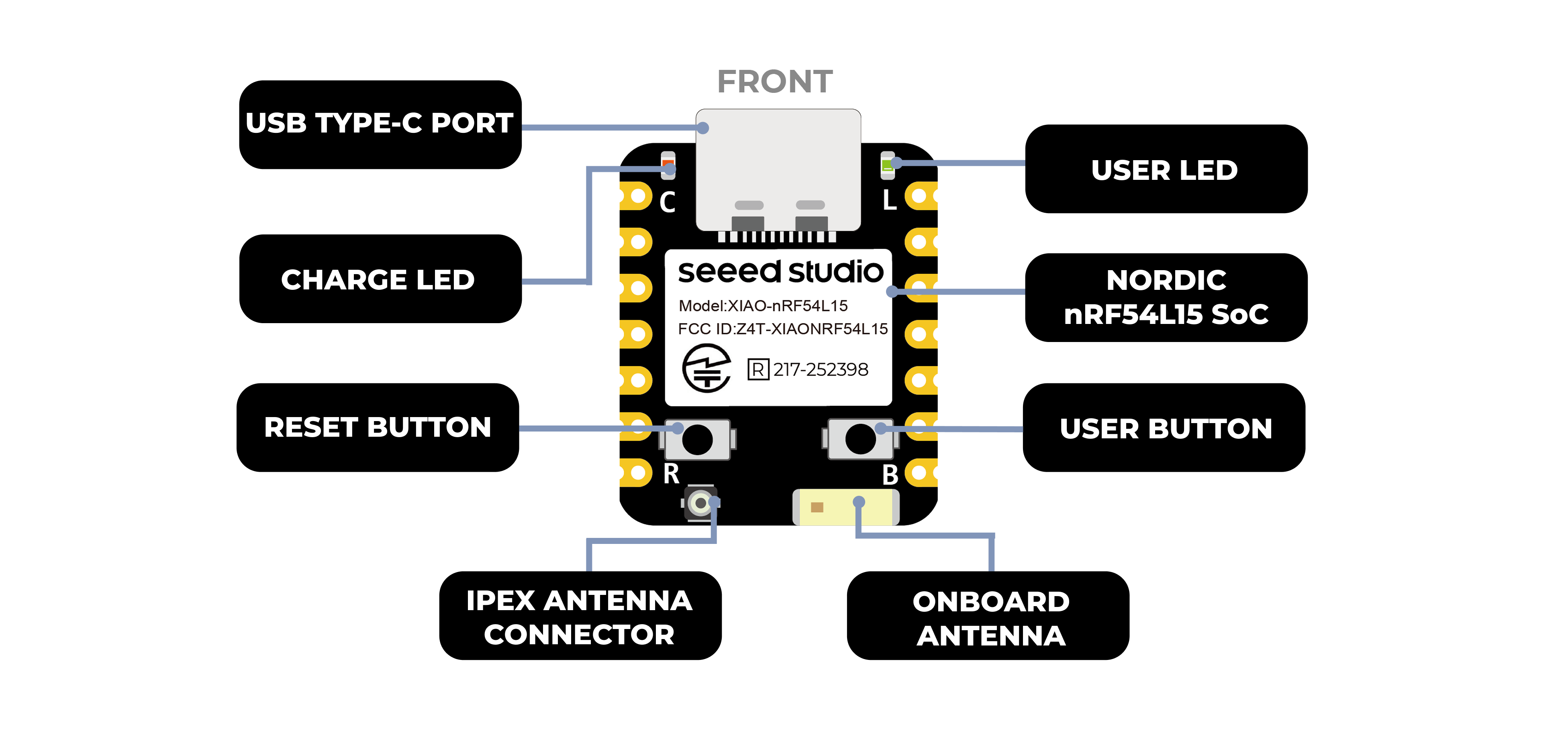 |
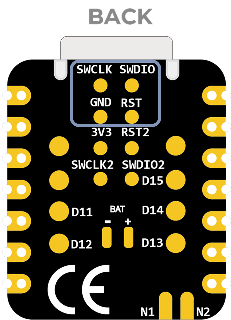
| XIAO nRF54L15 back indication diagram |
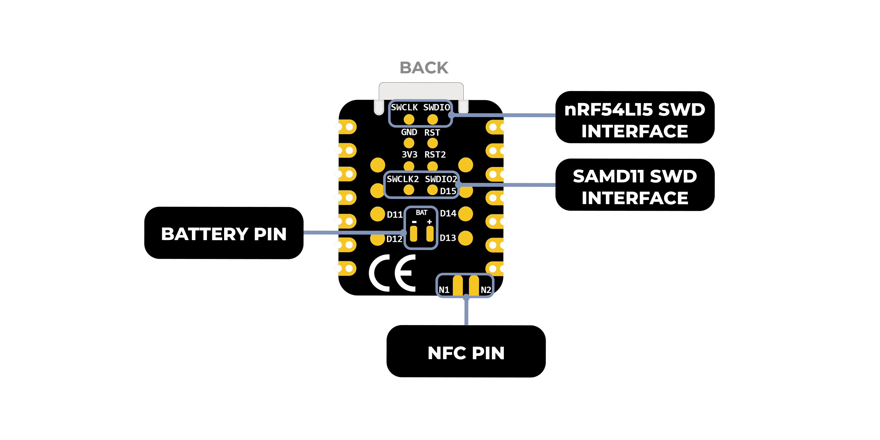 |
| XIAO nRF54L15 Pin List |
 |
| XIAO nRF54L15 Sense front indication diagram |
|---|
 |
| XIAO nRF54L15 Sense back indication diagram |
|
| XIAO nRF54L15 Sense Pin List |
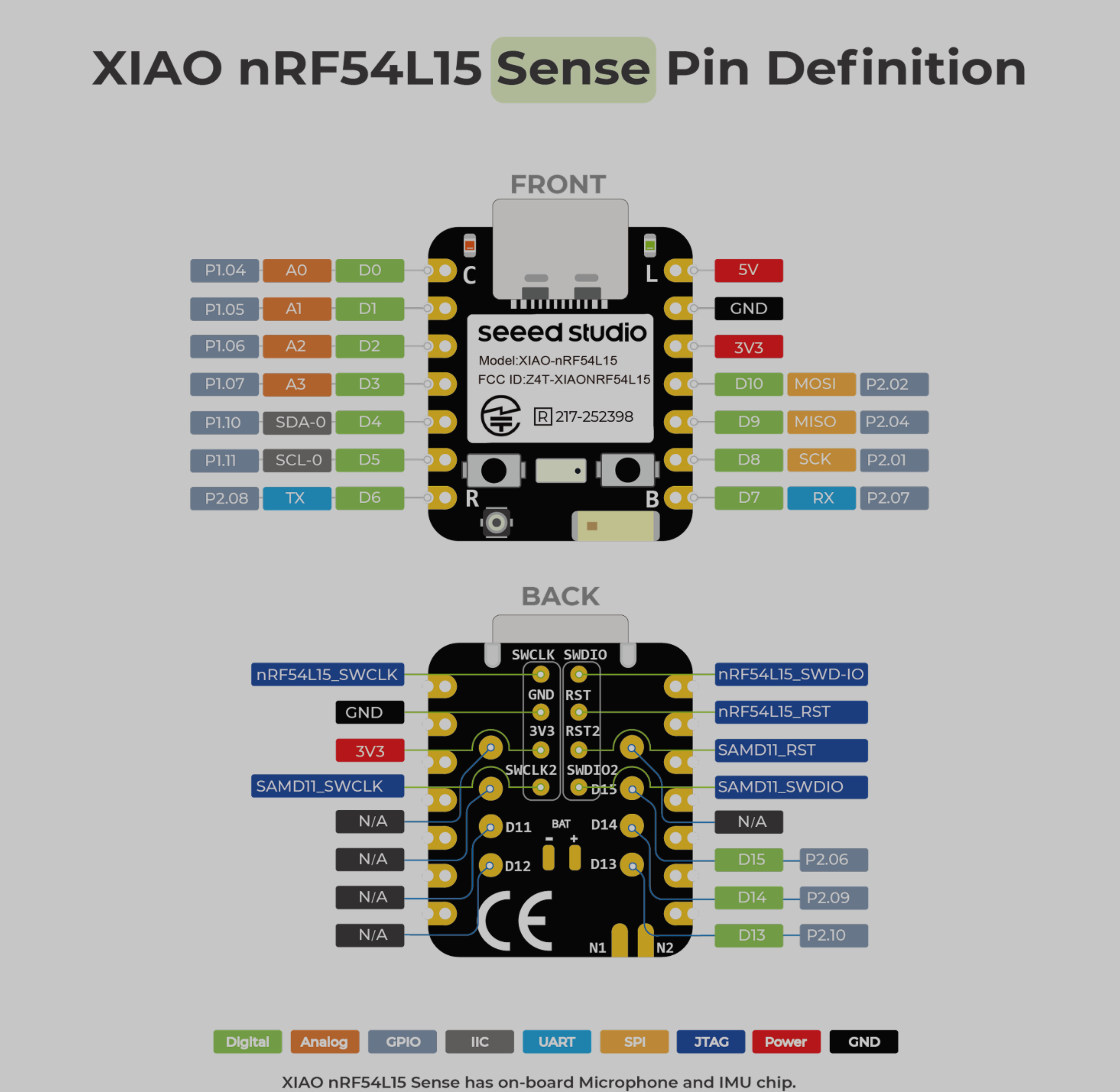 |
Pin Map
| XIAO Pin | Function | Chip Pin | Description |
|---|---|---|---|
| 5V | VBUS | Power Input/Output | |
| GND | |||
| 3V3 | 3V3_OUT | Power Output | |
| D0 | Analog | P1.04 | GPIO, ADC |
| D1 | Analog | P1.05 | GPIO, ADC |
| D2 | Analog | P1.06 | GPIO, ADC |
| D3 | Analog | P1.07 | GPIO, ADC |
| D4 | SDA-0 | P1.10 | GPIO, I2C Data |
| D5 | SCL-0 | P1.11 | GPIO, I2C Clock |
| D6 | TX | P2.08 | GPIO, UART Transmit |
| D7 | RX | P2.07 | GPIO, UART Receive |
| D8 | SPI_SCK | P2.01 | GPIO, SPI Clock |
| D9 | SPI_MISO | P2.04 | GPIO, SPI Data |
| D10 | SPI_MOSI | P2.02 | GPIO, SPI Data |
| D11 | SCL-1 | P0.03 | GPIO, I2C |
| D12 | SDA-1 | P0.04 | GPIO,I2C |
| D13 | GPIO | P2.10 | GPIO |
| D14 | GPIO | P2.09 | GPIO |
| D15 | GPIO | P2.06 | GPIO |
| nRF54L15_SWCLK | SWDCLK | JTAG | |
| nRF54L15_SWD-IO | SWDIO | JTAG | |
| nRF54L15_RST | RST | JTAG | |
| SAMD11_SWCLK | PA30 | JTAG | |
| SAMD11_SWDIO | PA31 | JTAG | |
| SAMD11_RST | RST2 | JTAG | |
| NFC1 | P1.02 | NRF | |
| NFC2 | P1.03 | NRF | |
| Reset | nRF54_RESET | EN | |
| USER KEY | P0.00 | User Key | |
| RF Switch Port Select | P2.05 | Switch onboard antenna | |
| RF Switch Power | P2.03 | Power | |
| AIN7_VBAT | P1.14 | Read the BAT voltage value | |
| CHARGE_LED | charge_LED | CHG-LED_Red | |
| USER_LED | P2.00 | User Light |
nRFConnect SDK Usage
The nRF Connect SDK (NCS) is an extensible, unified software development kit from Nordic Semiconductor specifically designed for building low-power wireless applications for Nordic nRF52, nRF53, nRF54, nRF70, and nRF91 series-based wireless devices.
NCS provides a rich ecosystem of off-the-shelf sample applications, protocol stacks, libraries and hardware drivers designed to simplify the development process and accelerate time-to-market. Its modular and configurable nature gives developers the flexibility to build size-optimized software for memory-constrained devices, as well as powerful functionality for more advanced and complex applications.NCS is an open-source project hosted on GitHub and offers excellent support for integrated development environments such as Visual Studio Code.
Using nRF Connect SDK on VSCode
Install nRF Connect SDK Knowledge in advance
This document details how to install the nRF Connect SDK development environment on a Windows 11 computer.The following is an overview of the tools that need to be installed
-
Install VS Studio Code
-
nRF Command Line Tools
-
nRF Connect for Desktop
-
Git
-
Ninja
ninja --version
- CMake
cmake --version
- Zephyr SDK
west --version
- nRF Connect SDK
- VSCode nRF Connect plugin
If you have pre-installed it on your computer, you can check the version number of your tool by following the command below
VScode configures the board and builds the burn-in file
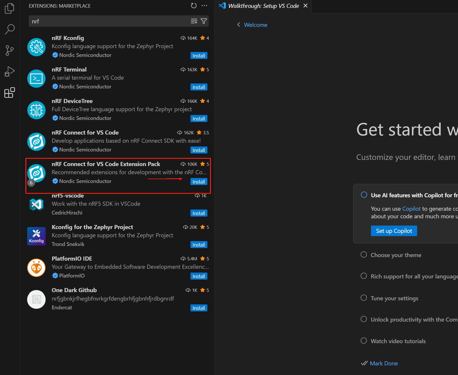
Open VS Code and search for nRF Connect for VS Code Extension Pack in the Plugin Center. This plugin pack will automatically install other VS Code plugins required for nRF Connect.
The nRF Connect for VS Code extension enables developers to utilize the popular Visual Studio Code Integrated Development Environment (VS Code IDE) to develop, build, debug and deploy embedded applications based on Nordic's nRF Connect SDK (Software Development Kit). The extension includes useful development tools such as a compiler interface, linker, complete build system, RTOS-enabled debugger, seamless interfacing with the nRF Connect SDK, device tree visualization editor, and an integrated serial terminal.
The nRF Connect extension package for VS Code includes the following components:
- nRF Connect for VS Code: The main extension contains the interface between the build system and the nRF Connect SDK, as well as an interface to manage the nRF Connect SDK version and toolchain.
- nRF DeviceTree: Provides device tree language support and a device tree visualization editor.
- nRF Kconfig: Provides Kconfig language support.
- nRF Terminal: Serial and RTT terminals.
- Microsoft C/C++: Adds language support for C/C++, including features of IntelliSense.
- CMake: CMake language support.
- GNU Linker Mapping Files: Support for linker mapping files. We can download any preferred version of the nRF Connect SDK and its toolchain via the extension. The full nRF Connect for VS Code documentation is available at https://docs.nordicsemi.com/bundle/nrf-connect-vscode/page/index.html.
Installing the toolchain
The toolchain is a collection of tools that work together to build nRF Connect SDK applications, including assembler, compiler, linker, and CMake components. The first time you open nRF Connect for VS Code, you will be prompted to install the toolchain. This usually happens if the extension does not detect any installed toolchain on your computer. Click Install Toolchain and a list of toolchain versions will be listed that can be downloaded and installed on your computer. Select the version of the toolchain that matches the version of the nRF Connect SDK you plan to use. We always recommend using the latest tagged version of the nRF Connect SDK.
By default, nRF Connect for VS Code only displays the Released tab (i.e., the stable version) of the toolchain. If you are evaluating a new feature and would like to use the Preview tab or another type of tab (e.g. Customer Sampling -cs), click on "Show all toolchain versions" as shown below:
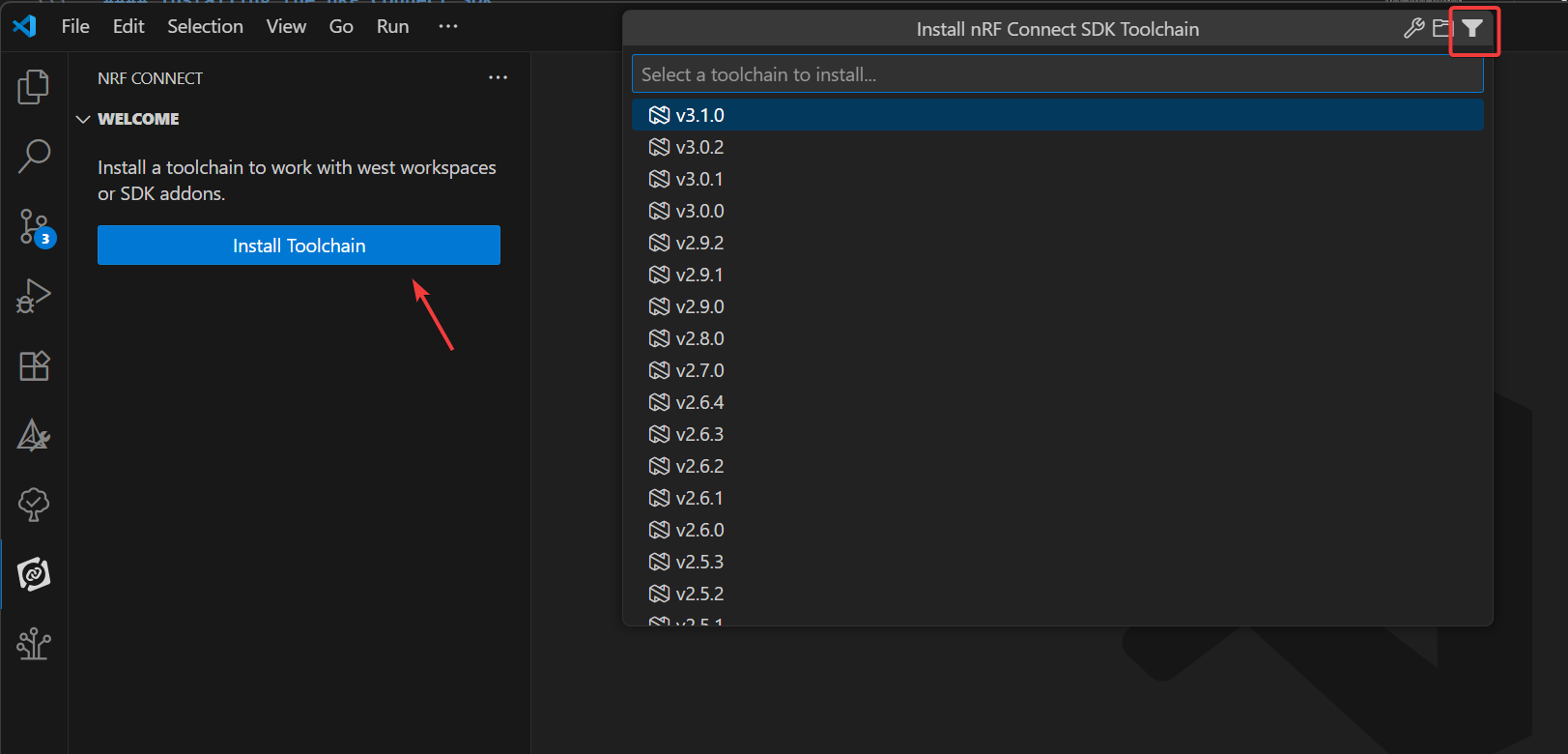
The ToolChain here is 3.0.1 or above
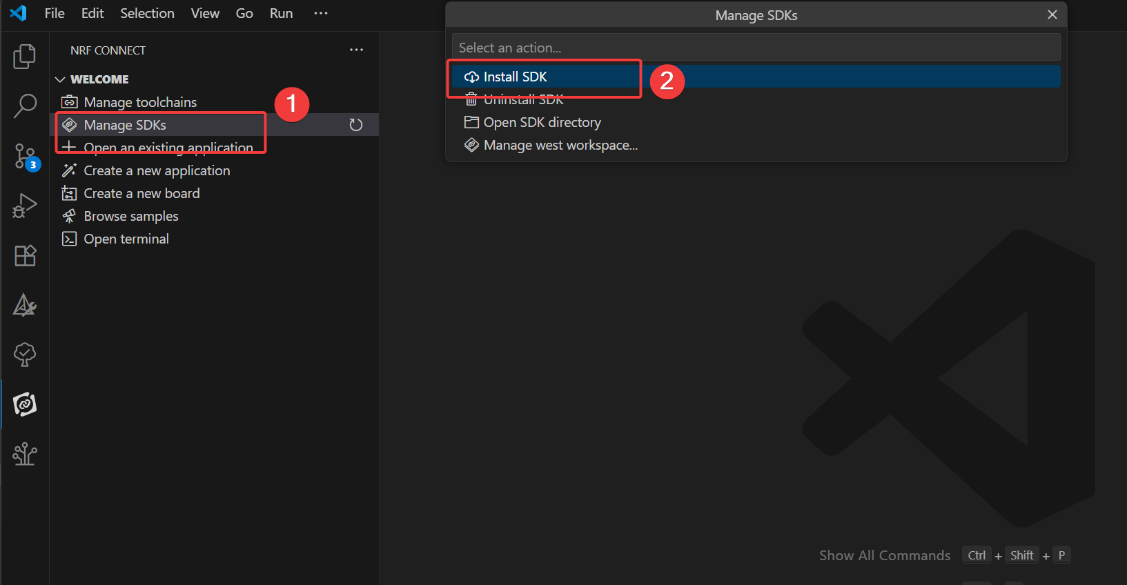
Installing the nRF Connect SDK
In the nRF Connect extension for VS Code, click on Manage SDK. from the Manage SDK menu, we can install or uninstall the nRF Connect SDK version. Since this is the first time we are using the extension, the interface will only show two options.
Clicking Install SDK will list all available nRF Connect SDK versions that can be downloaded and installed locally. Select the version of the nRF Connect SDK that is required for the development of your project.
If you have opened the SDK folder in VS Code, instead of the Manage SDK menu option, you will see the Manage west workspace. To resolve this issue, open another window or folder in VS Code.
The nRF Connect SDK here is 3.0.1 or above
If you do not see either of these options, make sure you have the latest version of the nRF Connect for VS Code extension package installed. It is important to note that the nRF Connect SDK is IDE independent, which means you can choose to use any IDE or none at all. The nRF Connect SDK is available via the https://www.nordicsemi.com/Products/Development-tools/nRF-Util (nrfutil) command line The (nrfutil) command line interface (CLI) will download and install nRF Connect. However, we highly recommend using our nRF Connect for VS Code extension with VS Code, as it integrates not only a convenient graphical user interface (GUI) and an efficient command line interface (CLI), but also includes a number of features that will greatly simplify firmware development. Configuring other IDEs to work with the nRF Connect SDK requires additional manual steps beyond the scope of this course.
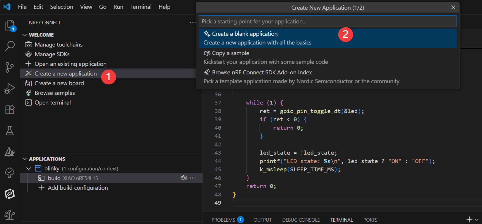
Creating User Programs
In this exercise we will write a simple application based on the blinky example to control blinking LEDs on a development board. The same applies to all supported NordicSemiconductor development boards (nRF54, nRF53, nRF52, nRF70 or nRF91 series). The goal is to make sure that all the tools needed to build and burn the example are set up correctly. The focus is on learning how to create an application, build it and burn it to a Nordic chip development board using the “Copy Example” template!
- In VS Code, click the nRF Connect extension icon. In the Welcome view, click Create New Application.
- Type blinky in the search bar and select the second Blinky sample (path zephyr/samples/basic/blinky), as shown below.
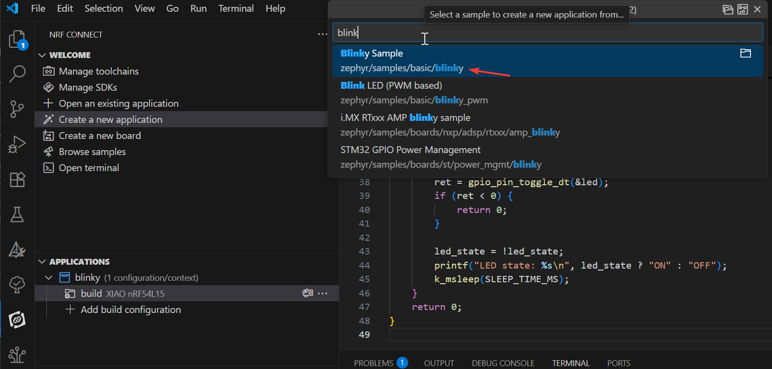
The Blinky example will cause the LED1 on the development board to blink continuously. Our first application will be based on the Blinky example. The Blinky example is derived from the Zephyr mold block in the nRF Connect SDK, so you will see the zephyr name in the sample path: zephyr\samples\basic\blinky.
Add XIAO nRF54L15 Board
To get started, clone the repository from the GitHub linkgit clone https://github.com/Seeed-Studio/platform-seeedboards.git into your preferred local folder. Once cloned, navigate to the platform-seeedboards/zephyr/ directory. Remember this zephyr folder Path;
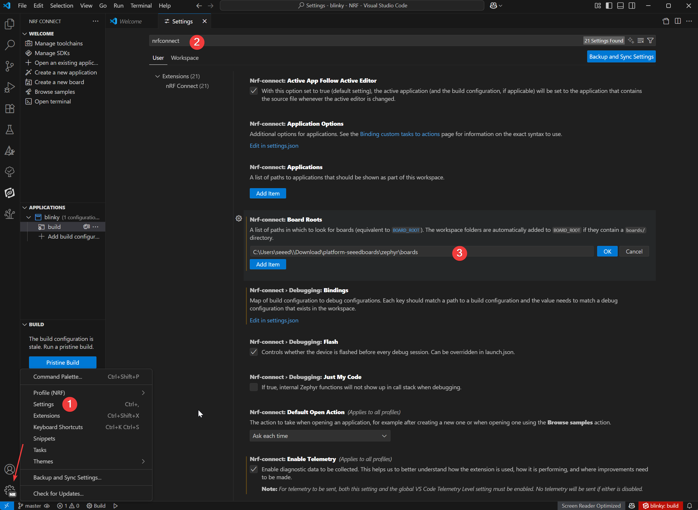
To configure your board for nRF Connect in VS Code, you can follow these steps:
-
Open VS Code and go to Settings.
-
Type nRF Connect in the search box.
-
Find the Board Roots settings item and click Edit in settings.json.
-
Add the
zephyrpath of the downloaded XIAO nRF54L15 board file to the boardRoots array.
-
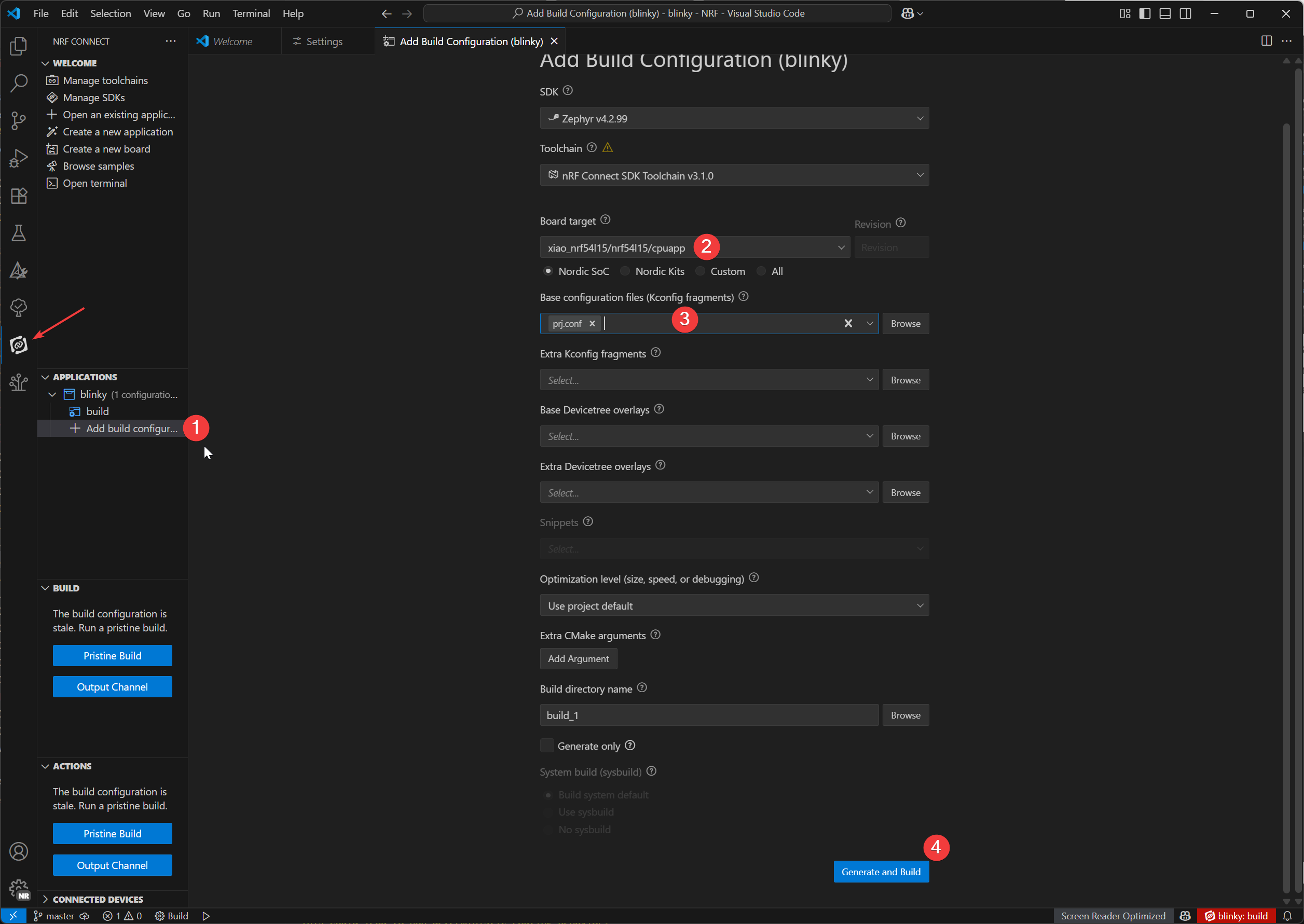
In the application view, click Add Build Configuration below the application name .
-
We can select the model of XIAO nRF54L15 in the Board target, and select the default prj.config file in the Base configuration files, and finally click
Generate and Buildto build the file.
Download Burn-in Plug-in
- Window
- Mac OS
Additional Plugins:
On Windows, we'll use the Chocolatey package manager to install OpenOCD.
1.Open PowerShell (Run as Administrator):
- In the Windows search bar, type "PowerShell".
- Right-click "Windows PowerShell" and select "Run as administrator".
2.Check PowerShell Execution Policy:
- Type
Get-ExecutionPolicyand press Enter. - Type
Get-ExecutionPolicy -Listand press Enter.
3.Install Chocolatey:
- Paste and run the following command:
Set-ExecutionPolicy Bypass -Scope Process -Force; [System.Net.ServicePointManager]::SecurityProtocol = [System.Net.ServicePointManager]::SecurityProtocol -bor 3072; iex ((New-Object System.Net.WebClient).DownloadString('https://community.chocolatey.org/install.ps1'))
This command bypasses the execution policy for the current PowerShell session and installs Chocolatey. After installation, close and reopen the PowerShell window (still run as administrator).
4.Install OpenOCD:
- In the new PowerShell window (as administrator), type:
choco install openocd
5.Verify OpenOCD Installation:
-
Type
Get-Command openocdand press Enter. -
If the installation is successful, this command will display the path to openocd.exe.
Additional Plugins:
On macOS, we'll use the Homebrew package manager to install the necessary tools.
1.Install Homebrew (if not already installed):
-
Open Terminal.app.
-
Run the following command:
/bin/bash -c "$(curl -fsSL https://raw.githubusercontent.com/Homebrew/install/HEAD/install.sh)"
- Follow the on-screen prompts; you might need to enter your macOS user password. After installation, run the commands prompted by the terminal to add Homebrew to your PATH environment variable
(e.g., eval "$(/opt/homebrew/bin/brew shellenv)"). Then close and reopen the terminal.
2.Install Ccache:
In the terminal, type:
brew install ccache
3.Install OpenOCD:
In the terminal, type:
brew install openocd
4.Verify OpenOCD Installation::
-
Type
which openocdand press Enter. -
If the installation is successful, this command will display the path to the
openocdexecutable.
West Flash burn-in program
-
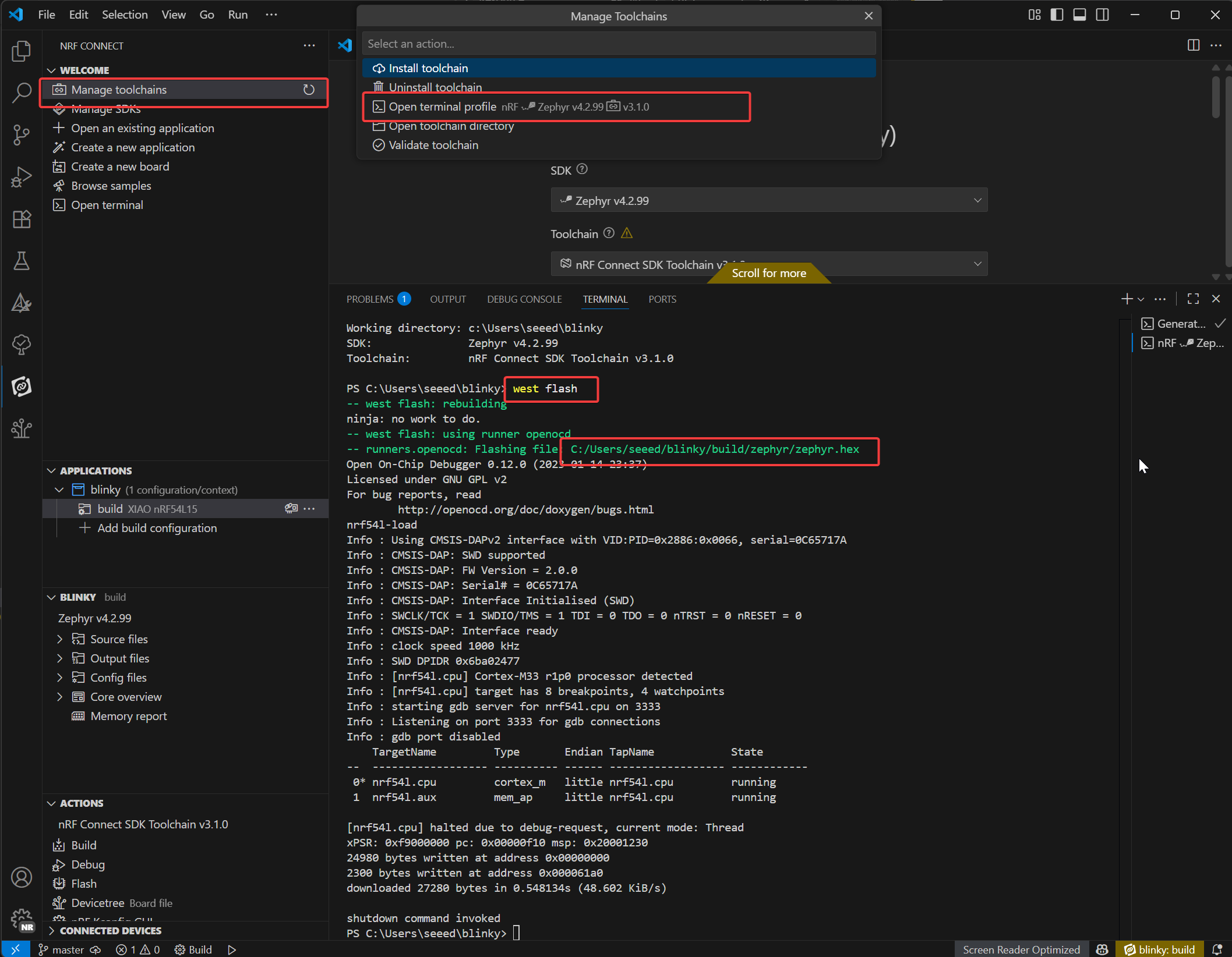
Open the nRF terminal
-
Just enter the
west flashcommand,To flash your device, simply enter the west flash command. The path highlighted in red indicates the location of your compiled .elf file. You can use this same path to find the corresponding .hex file, which is suitable for programming with a J-Link debugger.
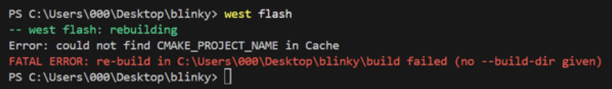
If the west flash error occurs, it means that there is a conflict with the CMake plugin in VS Code, and you need to remove the CMake plugin.
When we successfully burned the program in the Seeed Studio XIAO nRF54L15 Sense, you can see the board above the user indicator in the non-stop blinking green light, if your hands are also the same rendering effect, it means that you have been successfully on it!🎊
Blinky program explation
/*
 * Copyright (c) 2016 Intel Corporation
 *
 * SPDX-License-Identifier: Apache-2.0
 */

#include <stdio.h>
#include <zephyr/kernel.h>
#include <zephyr/drivers/gpio.h>

/* 1000 msec = 1 sec */
#define SLEEP_TIME_MS   1000

/* The devicetree node identifier for the "led0" alias. */
#define LED0_NODE DT_ALIAS(led0)

/*
 * A build error on this line means your board is unsupported.
 * See the sample documentation for information on how to fix this.
 */
static const struct gpio_dt_spec led = GPIO_DT_SPEC_GET(LED0_NODE, gpios);

int main(void)
{
int ret;
bool led_state = true;

if (!gpio_is_ready_dt(&led)) {
  return 0;
}

ret = gpio_pin_configure_dt(&led, GPIO_OUTPUT_ACTIVE);
if (ret < 0) {
  return 0;
}

while (1) {
  ret = gpio_pin_toggle_dt(&led);
  if (ret < 0) {
    return 0;
  }

  led_state = !led_state;
  printf("LED state: %s\n", led_state ? "ON" : "OFF");
  k_msleep(SLEEP_TIME_MS);
}
return 0;
}
LED Device Definition:
#define LED0_NODE DT_ALIAS(led0): Retrieves the device tree node identifier for the "led0" alias, enabling hardware-agnostic reference to the LED.static const struct gpio_dt_spec led = GPIO_DT_SPEC_GET(LED0_NODE, gpios): Creates a GPIO specification structure (led) using the device tree node, containing hardware details (pin, port) for the LED. A build error here indicates unsupported hardware.
main() Function Initialization:
-
Variable Setup:
int ret: Stores function return values to check operation success.bool led_state = true: Tracks LED status (initialized to "ON").
-
GPIO Readiness Check:
if (!gpio_is_ready_dt(&led)) { return 0; }: Verifies if the LED's GPIO hardware is ready (e.g., driver loaded). Exits if not ready.
-
GPIO Configuration:
ret = gpio_pin_configure_dt(&led, GPIO_OUTPUT_ACTIVE): Configures the LED's GPIO pin as an active-high output.- Exits on failure (
ret < 0) to prevent invalid operations.
Main Loop:
Runs in an infinite while (1) loop to toggle the LED periodically:
-
Toggle LED State:
ret = gpio_pin_toggle_dt(&led): Flips the LED's GPIO output (ON ↔ OFF). Exits on failure.
-
Update Status Tracking:
led_state = !led_state: Syncs the software status flag with hardware state.
-
Log and Delay:
printf("LED state: %s\n", led_state ? "ON" : "OFF"): Prints current LED status via serial output.k_msleep(SLEEP_TIME_MS): Pauses for 1000ms (1 second) using Zephyr's RTOS delay function, controlling the blink frequency.
Deep Dive into nRF Connect SDK Internals
If you want to have a deeper understanding of the internal principles of nRF Connect SDK, you can refer to the following courses:
Restore factory settings
For XIAO nRF54L15 boards, a factory reset script is provided to recover the board from a bad state (e.g., when it's can not upload due to the internal NVM write protection). This script will perform a mass erase of the flash and program a factory firmware.
Location The scripts are located in the scripts/factory_reset/ directory. Usage The script will automatically create and manage a local Python virtual environment to install the necessary tools, so it can be run out-of-the-box.
Window
- For Windows: Navigate to the scripts/factory_reset directory and run:
.\factory_reset.bat
Linux-MacOS
- For Linux and macOS: Navigate to the scripts/factory_reset directory and run:
bash factory_reset.sh
Wireless Switching Mode
This example demonstrates how to control the RF switch on the Seeed Studio XIAO nRF54L15 to toggle between the onboard
::: The following example works for both PlatformIO and nRF Connect SDK. It can be used directly in PlatformIO, while the SDK requires manually adding files. Refer to this link :::
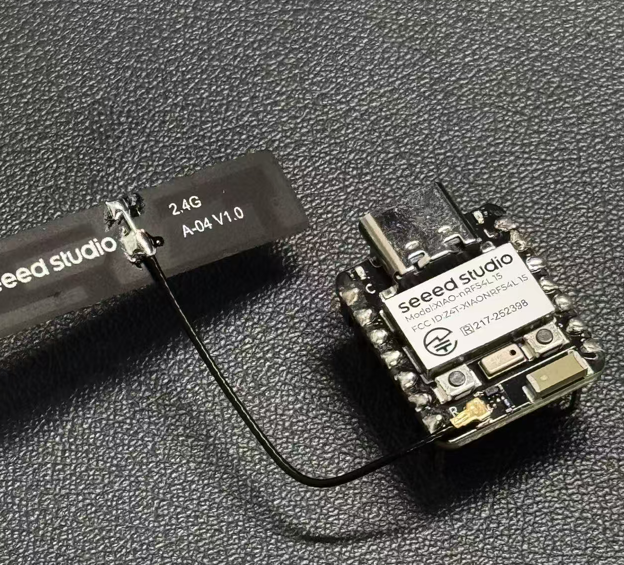
External antenna
-
Ceramic antenna and an external antenna.
-
Press the user button (SW0) to switch between the ceramic and external antennas.
-
The user LED indicates the current antenna selection (LED ON for external, LED OFF for ceramic).
-
The default antenna at startup can be configured via prj.conf.
/*
 * Copyright (c) 2024 Seeed Technology Co.,Ltd
 *
 * SPDX-License-Identifier: Apache-2.0
 */

#include <zephyr/kernel.h>
#include <zephyr/device.h>
#include <zephyr/drivers/gpio.h>
#include <zephyr/logging/log.h>
#include <zephyr/devicetree.h>

LOG_MODULE_REGISTER(app, CONFIG_LOG_DEFAULT_LEVEL);

/* Devicetree node identifiers */
#define RFSW_REGULATOR_NODE DT_NODELABEL(rfsw_ctl)
#define SW0_NODE            DT_ALIAS(sw0)
#define LED0_NODE           DT_ALIAS(led0)

/* State variables */
static uint8_t onoff_flag = 0;
#ifdef CONFIG_DEFAULT_ANTENNA_EXTERNAL
static bool is_external_antenna = true;
#else
static bool is_external_antenna = false;
#endif

/* GPIO device specs */
/* Manually build gpio_dt_spec for rfsw_ctl */
static const struct gpio_dt_spec rfsw_gpio = {
	.port = DEVICE_DT_GET(DT_GPIO_CTLR(RFSW_REGULATOR_NODE, enable_gpios)),
	.pin = DT_GPIO_PIN(RFSW_REGULATOR_NODE, enable_gpios),
	.dt_flags = DT_GPIO_FLAGS(RFSW_REGULATOR_NODE, enable_gpios),
};
static const struct gpio_dt_spec button = GPIO_DT_SPEC_GET(SW0_NODE, gpios);
static const struct gpio_dt_spec led = GPIO_DT_SPEC_GET(LED0_NODE, gpios);

/* Button callback data */
static struct gpio_callback button_cb_data;

/* Forward declarations */
void button_pressed(const struct device *dev, struct gpio_callback *cb, uint32_t pins);
void update_antenna_switch(void);

/* Function to update antenna switch and LED */
void update_antenna_switch(void)
{
    int ret;
    is_external_antenna = !is_external_antenna;

    if (is_external_antenna) {
        /* Switch to external antenna */
        LOG_INF("Switching to External Antenna");

        // To get a physical high level (Inactive state), we need to set the logic to '0'
        ret = gpio_pin_set_dt(&rfsw_gpio, 0);
        if (ret < 0) {
            LOG_ERR("Error setting rfsw-ctl to physical HIGH: %d\n", ret);
        }

        // Turn on the LED (set 0 for on)
        ret = gpio_pin_set_dt(&led, 0);
        if (ret < 0) {
            LOG_ERR("Error turning on LED: %d\n", ret);
        }

    } else {
        /* Switch back to ceramic antenna */
        LOG_INF("Switching to Ceramic Antenna");

        // To get a physical low level (Active state), we need to set the logic to '1'
        ret = gpio_pin_set_dt(&rfsw_gpio, 1);
        if (ret < 0) {
            LOG_ERR("Error setting rfsw-ctl to physical LOW: %d\n", ret);
        }

        // Turn off the LED (set 1 for off)
        ret = gpio_pin_set_dt(&led, 1);
        if (ret < 0) {
            LOG_ERR("Error turning off LED: %d\n", ret);
        }
    }
}

/* Button pressed callback function */
void button_pressed(const struct device *dev, struct gpio_callback *cb,
                    uint32_t pins)
{
    update_antenna_switch();
}

int main(void)
{
    int ret;

    /* Check if GPIO devices are ready */
    if (!gpio_is_ready_dt(&rfsw_gpio)) {
        LOG_ERR("RF switch control GPIO not ready\n");
        return -1;
    }
    if (!gpio_is_ready_dt(&button)) {
        LOG_ERR("Button GPIO not ready\n");
        return -1;
    }
    if (!gpio_is_ready_dt(&led)) {
        LOG_ERR("LED GPIO not ready\n");
        return -1;
    }

    /* Configure GPIO pins */
    ret = gpio_pin_configure_dt(&rfsw_gpio, GPIO_OUTPUT);
    if (ret < 0) {
        LOG_ERR("Error configuring rfsw-ctl: %d\n", ret);
        return ret;
    }

    /* Configure LED as output, default off */
    ret = gpio_pin_configure_dt(&led, GPIO_OUTPUT_ACTIVE);
    if (ret < 0) {
        LOG_ERR("Error configuring LED: %d\n", ret);
        return ret;
    }

    /* Set initial LED state based on antenna selection */
    if (is_external_antenna) {
        // External antenna
        LOG_INF("Initial state: External Antenna");
        ret = gpio_pin_set_dt(&rfsw_gpio, 0);
        if (ret < 0) {
            LOG_ERR("Error setting rfsw-ctl to physical HIGH: %d\n", ret);
        }
        ret = gpio_pin_set_dt(&led, 0);  // Turn on LED
        if (ret < 0) {
            LOG_ERR("Error turning on LED: %d\n", ret);
        }
    } else {
        // Ceramic antenna
        LOG_INF("Initial state: Ceramic Antenna");
        ret = gpio_pin_set_dt(&rfsw_gpio, 1);
        if (ret < 0) {
            LOG_ERR("Error setting rfsw-ctl to physical LOW: %d\n", ret);
        }
        ret = gpio_pin_set_dt(&led, 1);  // Turn off LED
        if (ret < 0) {
            LOG_ERR("Error turning off LED: %d\n", ret);
        }
    }

    /* Configure button as input */
    ret = gpio_pin_configure_dt(&button, GPIO_INPUT);
    if (ret < 0) {
        LOG_ERR("Error configuring button: %d\n", ret);
        return ret;
    }

    /* Configure button interrupt */
    ret = gpio_pin_interrupt_configure_dt(&button, GPIO_INT_EDGE_TO_ACTIVE);
    if (ret < 0) {
        LOG_ERR("Error configuring button interrupt: %d\n", ret);
        return ret;
    }

    /* Initialize button callback */
    gpio_init_callback(&button_cb_data, button_pressed, BIT(button.pin));
    gpio_add_callback(button.port, &button_cb_data);

    LOG_INF("Antenna switch example started. Press SW0 to switch.\n");
    return 0;
}
If you wish to switch between the external or internal antenna, you need to modify the zephyr/prj.conf file., Uncomment # CONFIG_DEFAULT_ANTENNA_EXTERNAL=y to enable the external antenna. If using the internal antenna, comment out the line.
CONFIG_GPIO=y
CONFIG_SERIAL=y
CONFIG_LOG=y
CONFIG_CONSOLE=y
CONFIG_UART_CONSOLE=y
CONFIG_SHELL_BACKEND_SERIAL=y
CONFIG_SHELL_BACKEND_DUMMY=n
CONFIG_PM_DEVICE=y
CONFIG_NRFX_POWER=y
CONFIG_POWEROFF=y

CONFIG_BT=y
CONFIG_BT_PERIPHERAL=y
CONFIG_BT_DEVICE_NAME="zephyr-ble"

# Enable this option to default to external antenna
# CONFIG_DEFAULT_ANTENNA_EXTERNAL=y
Acess The J-Link Pins For Burn a Program
If you want to use JLink for programming, you can follow the steps below. However, we suggest that you use the serial port built-in on the Seeed Stduio XIAO nRF54L15 board for programming, which will be much more convenient.
Hardware Required
You need to download the latest version of J-Link to have the nRF54L15 model board support.
Software Required
It is required to download the Segger software from the website.
- Step 1. Use Jlink to connect pins below:
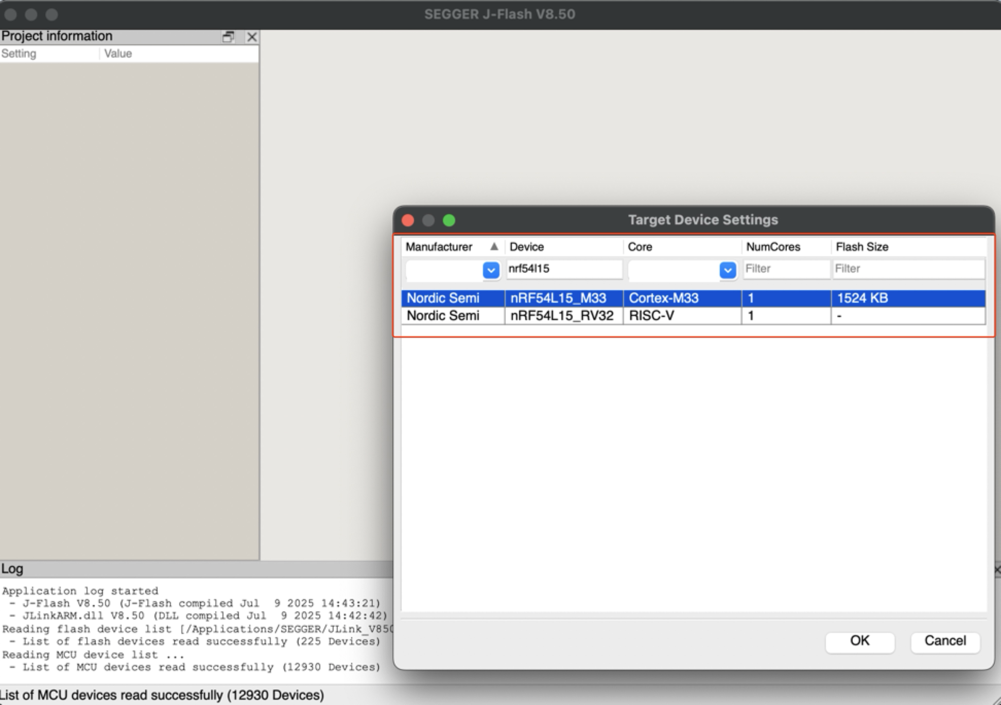
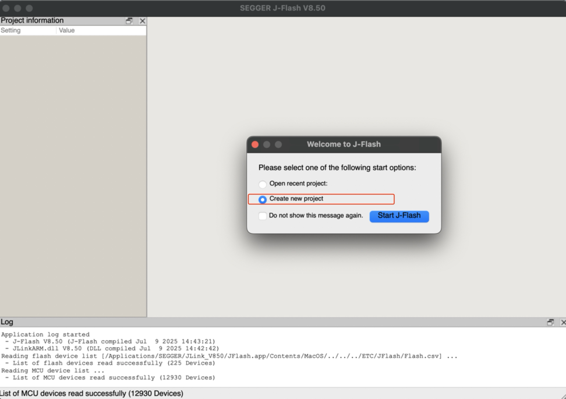
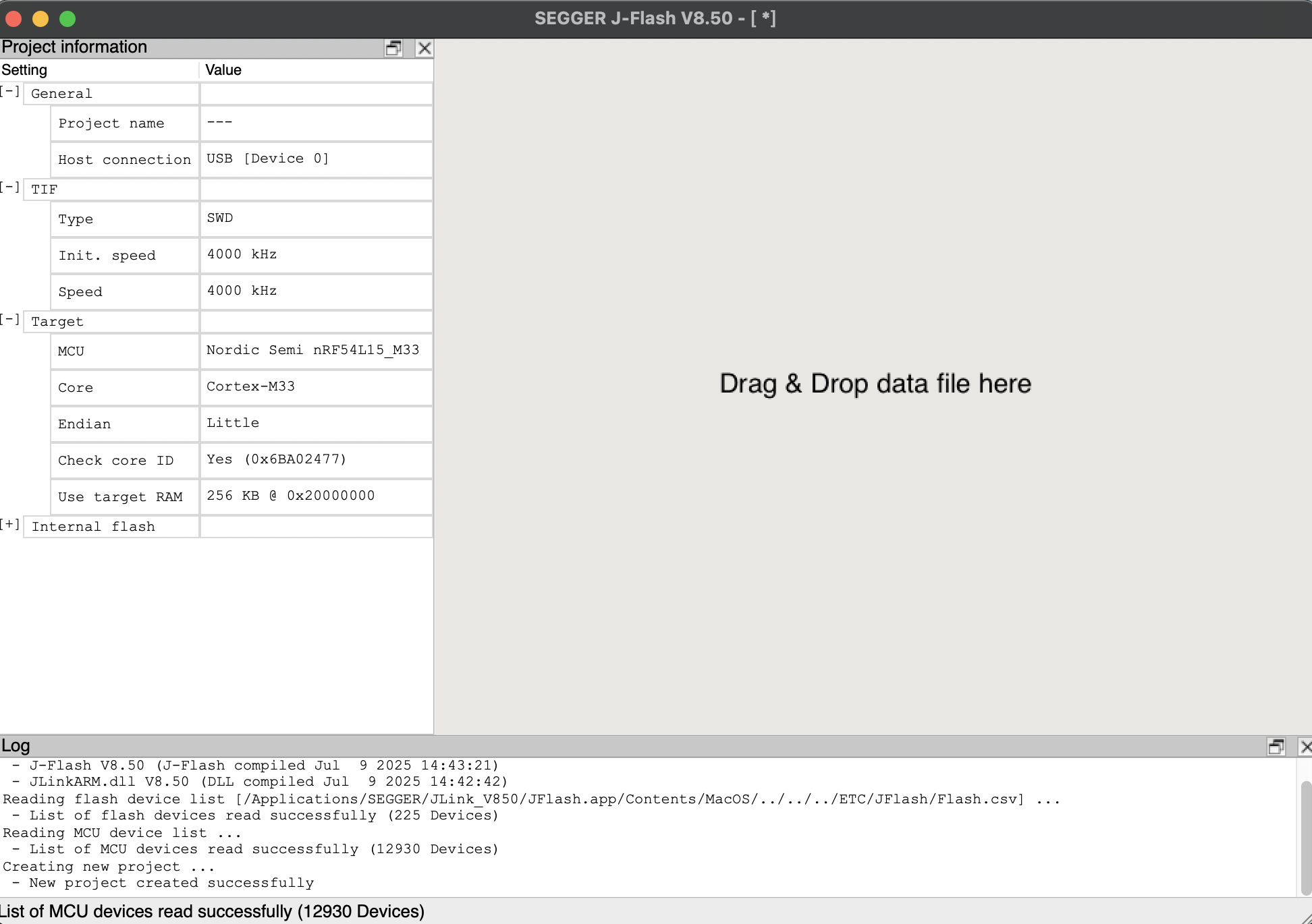
- Step 2. Start the J-Flash and search nRF54L15_M33, creating a new project:
- Step 3. Click "Target" and then select "Connect".
- Step 4. Draw the bin or hex file to software. Then press F4 and F5 in that order. The reflashing is done.
Battery Powered Board
The XIAO nRF54L15 has a built-in power management chip that allows the XIAO nRF54L15 to be powered independently by using a battery or to charge the battery through the XIAO nRF54L15's USB port.
If you want to connect the battery for XIAO, we recommend you to purchase qualified rechargeable 3.7V lithium battery. When soldering the battery, please be careful to distinguish between the positive and negative terminals.
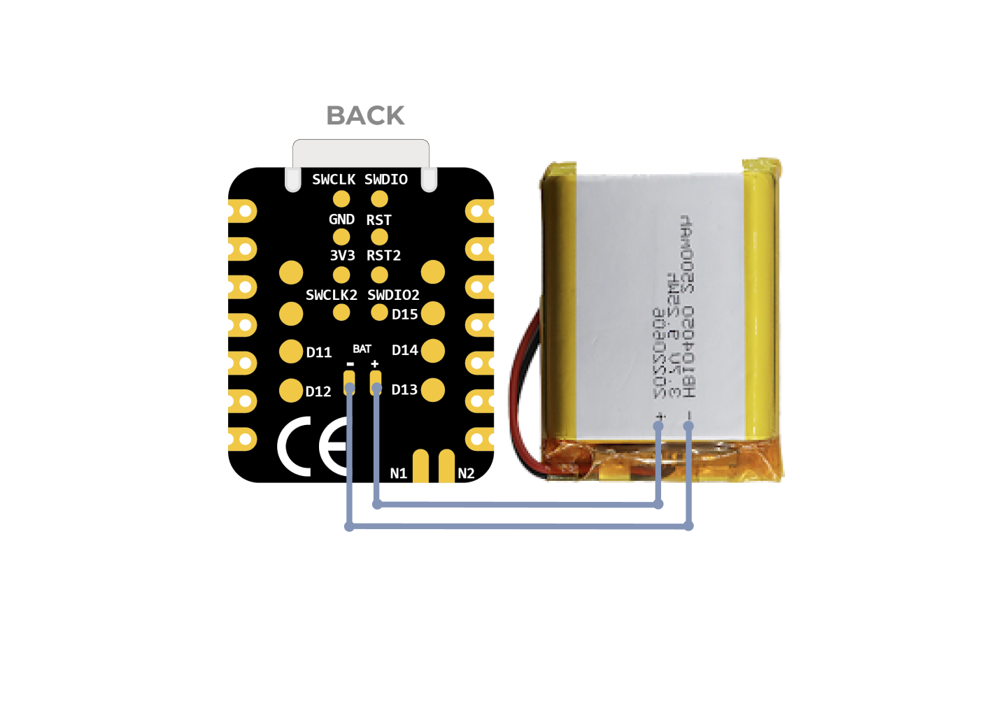
Battery Connecting Schematic
Instructions on the use of batteries:
- Please use qualified batteries that meet the specifications.
- XIAO can be connected to your computer device via data cable while using the battery, rest assured that XIAO has a built-in circuit protection chip, which is safe.
- The XIAO nRF54L15 will not have any LED on when it is battery powered (unless you have written a specific program), please do not judge whether the XIAO nRF54L15 is working or not by the condition of the LED, please judge it reasonably by your program.
At the same time, we designed a red indicator light for battery charging, through the indicator light display to inform the user of the current state of the battery in the charge.
Please be careful not to short-circuit the positive and negative terminals and burn the battery and equipment when soldering.
Battery Voltage Detection
If you encounter a situation where the XIAO nRF54L15 fails to boot when powered solely by a 3.7V lithium battery after flashing the program, please refer to the solutions below.
For the current hardware version (v1.0), we recommend managing two build configurations to switch easily between Bench Debugging (USB connected, UART enabled) and Battery Deployment (Standalone, UART disabled).
Scenario A: USB Bench Debugging
When to use: You are writing code, flashing firmware, and need to view logs via the USB Serial Port.
Configuration (prj_uart.conf):
Create a new file named prj_uart.conf in your project directory. This overlay file will temporarily re-enable UART for debugging purposes.
# Enable UART for USB debugging
CONFIG_SERIAL=y
CONFIG_UART_CONSOLE=y
# Optional: Keep RTT enabled as a secondary logging backend
CONFIG_USE_SEGGER_RTT=y
CONFIG_RTT_CONSOLE=y
CONFIG_LOG_BACKEND_RTT=y
CONFIG_LOG_BACKEND_UART=y
How to Build: Add the overlay configuration argument when building your project.
# Build with UART enabled for USB debugging
west build -p always -d build_uart -b xiao_nrf54l15/nrf54l15/cpuapp . -DOVERLAY_CONFIG="prj_uart.conf"
Scenario B: Battery Deployment (Default)
When to use: You have finished debugging and intend to power the board solely via the Battery Pads.
Configuration (prj.conf):
Modify your main prj.conf file to disable UART by default. This ensures the board can boot correctly when powered by a battery.
# Disable UART to ensure successful boot on battery
CONFIG_SERIAL=n
CONFIG_UART_CONSOLE=n
# Use RTT for low-power logging (requires J-Link)
CONFIG_USE_SEGGER_RTT=y
CONFIG_RTT_CONSOLE=y
CONFIG_LOG=y
CONFIG_LOG_BACKEND_RTT=y
How to Build: Build normally without the overlay argument.
# Build default firmware (Battery Safe)
west build -p always -d build_batt -b xiao_nrf54l15/nrf54l15/cpuapp .
Summary
- Plugged in via USB Use the
prj_uart.confoverlay to enable the Serial Monitor. - Running on Battery Use the default
prj.confto ensure the device boots without issues.
The XIAO nRF54L15 integrates a battery voltage detection feature that centers on efficiently managing battery power measurements using the TPS22916CYFPR load switch. This guide will focus on analyzing the software implementation of the battery detection (especially the main.c code) and guide you on how to easily deploy and use this feature in a PlatformIO environment, avoiding the complexity of the Zephyr NCS SDK.
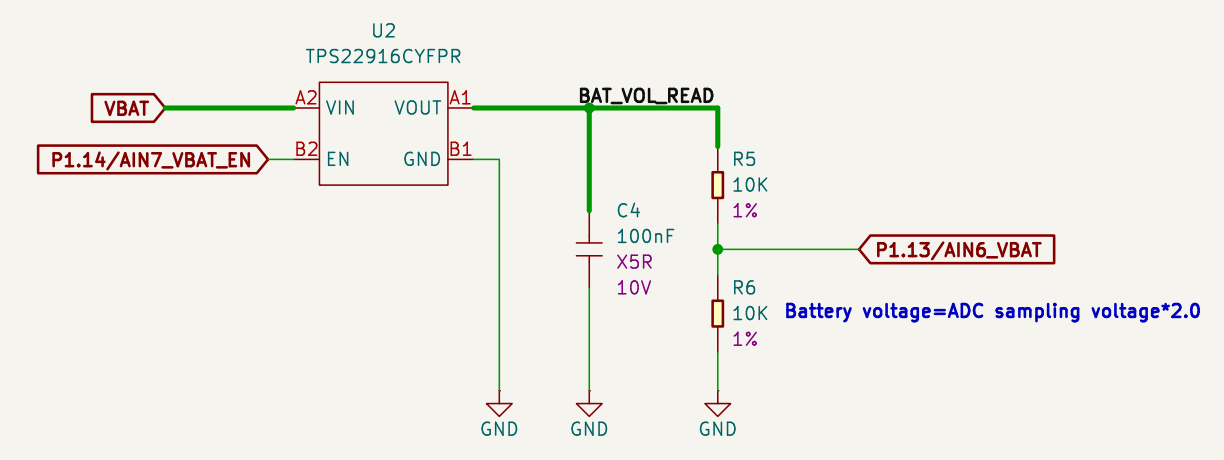
Detecting Battery Schematic
What the TPS22916CYFPR chip does:
-
It is an intelligent power switch that controls the on-off of the battery voltage on demand. When the battery voltage needs to be measured, it will turn on, connecting the battery to the voltage divider circuit; when it does not need to be measured, it will turn off, disconnecting the connection.
-
What does this feature help us do? Through this on-demand switching mechanism, the chip greatly reduces unnecessary current consumption and effectively extends battery life. Combined with the subsequent voltage divider circuit and the nRF54L15's ADC (analog-to-digital converter), the XIAO nRF54L15 is able to accurately monitor the battery's remaining charge, providing important range optimization for battery-powered, low-power applications such as IoT devices.
The following sample code is designed for PlatformIO, but it is also compatible with the nRF Connect SDK.
Using XIAO nRF54L15 in PlatformIO If you want to use XIAO nRF54L15 in PlatformIO, please refer to this tutorial to configure it: XIAO nRF54L15 PlatformIO Configuration.
Add overlay and modify the conf file
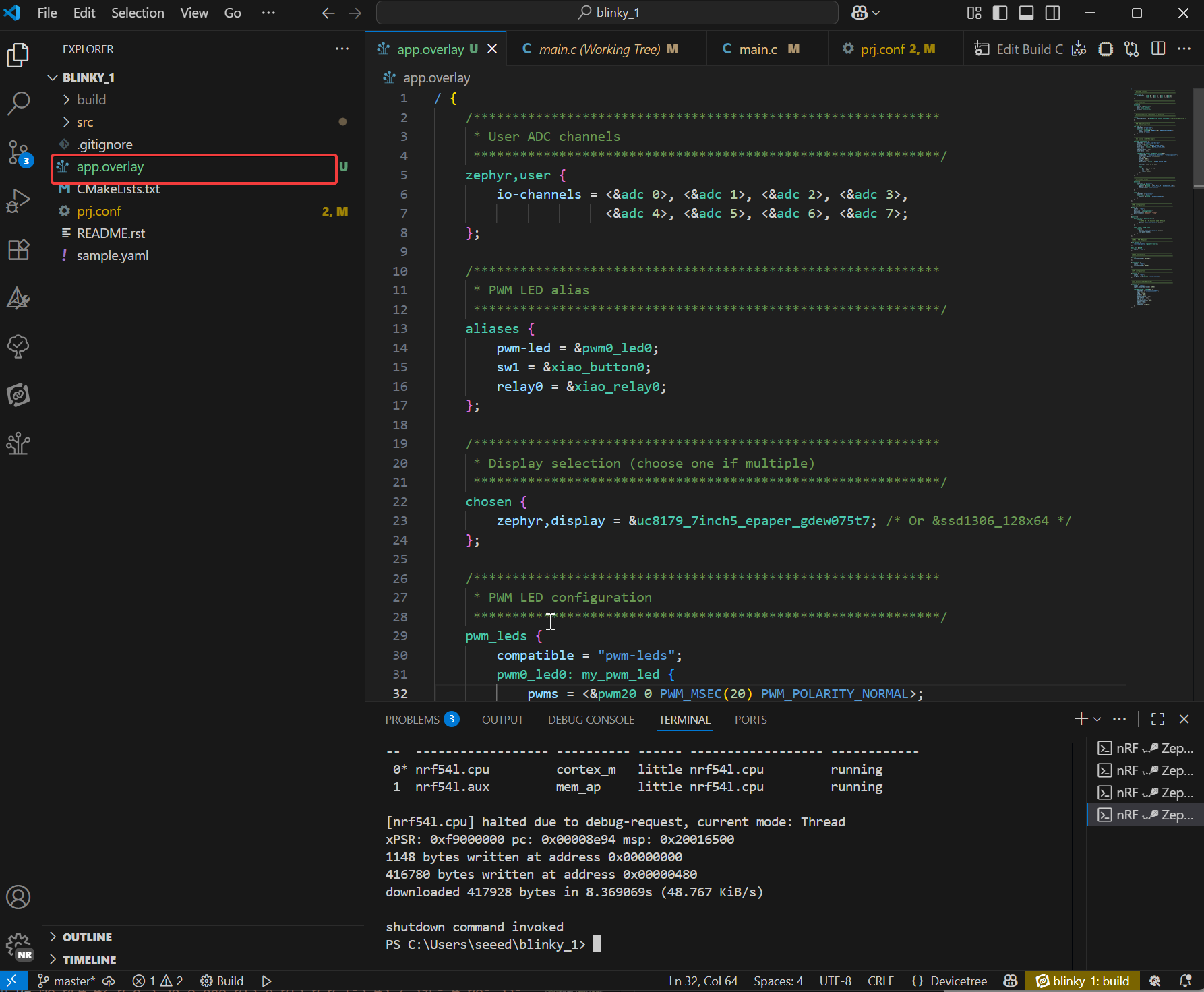
If you want to use this battery routine in the nRF Connect SDK, you need to add app.overlay and modify the prj.conf file.
-
Create a new file named
app.overlayunder the project directory. Then paste the following code into it, and finally press Ctrl + S to save.- The overlay file extends the hardware description layer and customizes the physical hardware connections through the device tree. It does not modify the code logic, but rather declares the actual hardware details to ensure that the driver can correctly initialize the physical device.
app.overlay code
/ {
/*
  * @brief Device Tree Overlay for XIAO nRF54L15
  *
  * This file customizes the base board device tree to configure
  * peripherals for a specific application, including:
  * - User-defined ADC channels
  * - PWM-controlled LED
  * - Buttons and a relay
  * - E-paper display (UC8179) via SPI
  * - OLED display (SSD1306) via I2C
  *
  * To switch between the two displays, simply uncomment one and comment
  * out the other in the "chosen" node below.
  */

/************************************************************
  * Aliases for easy access to devices in application code
  ************************************************************/
aliases {
  pwm-led = &pwm0_led0;
  sw1 = &xiao_button0;
  relay0 = &xiao_relay0;
};

/************************************************************
  * Display selection (choose one if multiple)
  ************************************************************/
chosen {
  zephyr,display = &uc8179_7inch5_epaper_gdew075t7;
  zephyr,display = &ssd1306_128x64;
};

/************************************************************
  * PWM LED, Button, and Relay configuration
  ************************************************************/
pwm_leds {
  compatible = "pwm-leds";
  pwm0_led0: my_pwm_led {
    // PWM channel 0 on PWM instance 20
    // PWM_MSEC(20) sets a period of 20ms
    pwms = <&pwm20 0 PWM_MSEC(20) PWM_POLARITY_NORMAL>;
    status = "okay";
  };
};

buttons {
  compatible = "gpio-keys";
  xiao_button0: button_0 {
    // Connect to the XIAO nRF54L15 pin D1
    // GPIO_PULL_UP ensures the pin is high when the button is not pressed
    // GPIO_ACTIVE_LOW means the button press drives the pin low
    gpios = <&xiao_d 1 (GPIO_PULL_UP | GPIO_ACTIVE_LOW)>;
    zephyr,code = <INPUT_KEY_0>;
  };
};

relay {
  compatible = "gpio-leds";
  xiao_relay0: relay_0 {
    // Connect to the XIAO nRF54L15 pin D0
    gpios = <&xiao_d 0 GPIO_ACTIVE_HIGH>;
  };
};

/************************************************************
  * Local nodes that don't modify existing ones
  ************************************************************/
zephyr,user {
  io-channels = <&adc 0>, <&adc 1>, <&adc 2>, <&adc 3>,
          <&adc 4>, <&adc 5>, <&adc 6>, <&adc 7>;
};

// MIPI-DBI SPI interface for the E-paper display
mipi_dbi_xiao_epaper {
  compatible = "zephyr,mipi-dbi-spi";
  spi-dev = <&xiao_spi>;
  // D3 pin for Data/Command control
  dc-gpios = <&xiao_d 3 GPIO_ACTIVE_HIGH>;
  // D0 pin for Reset
  reset-gpios = <&xiao_d 0 GPIO_ACTIVE_LOW>;
  write-only;
  #address-cells = <1>;
  #size-cells = <0>;

  uc8179_7inch5_epaper_gdew075t7: uc8179@0 {
    compatible = "gooddisplay,gdew075t7", "ultrachip,uc8179";
    // Max SPI frequency for the display
    mipi-max-frequency = <4000000>;
    reg = <0>;
    width = <800>;
    height = <480>;
    // D2 pin for Busy signal from the display
    busy-gpios = <&xiao_d 2 GPIO_ACTIVE_LOW>;
    softstart = [17 17 17 17];
    full {
      pwr = [07 07 3f 3f];
      cdi = <07>;
      tcon = <0x22>;
    };
  };
};
};

/************************************************************
* Device fragments (modifying nodes from the base board DTS)
************************************************************/
// PWM instance 20
&pwm20 {
status = "okay";
pinctrl-0 = <&pwm20_default>;
pinctrl-1 = <&pwm20_sleep>;
pinctrl-names = "default", "sleep";
};

// GPIO pin control
&pinctrl {
pwm20_default: pwm20_default {
  group1 {
    // Configure PWM channel 0 on P1.04 pin (Pin D0)
    psels = <NRF_PSEL(PWM_OUT0, 1, 4)>;
  };
};

pwm20_sleep: pwm20_sleep {
  group1 {
    psels = <NRF_PSEL(PWM_OUT0, 1, 4)>;
    low-power-enable;
  };
};
};

// PDM instance 20 for DMIC
dmic_dev: &pdm20 {
status = "okay";
};

// Power configuration
&pdm_imu_pwr {
/delete-property/ regulator-boot-on;
};

// UART instance 20
&uart20 {
current-speed = <921600>;
};

// SPI peripheral
&xiao_spi {
status = "okay";
// D1 pin for Chip Select
cs-gpios = <&xiao_d 1 GPIO_ACTIVE_LOW>;
};

// I2C peripheral
&xiao_i2c {
status = "okay";
zephyr,concat-buf-size = <2048>;

ssd1306_128x64: ssd1306@3c {
  compatible = "solomon,ssd1306fb";
  reg = <0x3c>;
  width = <128>;
  height = <64>;
  segment-offset = <0>;
  page-offset = <0>;
  display-offset = <0>;
  multiplex-ratio = <63>;
  segment-remap;
  com-invdir;
  prechargep = <0x22>;
};
};
-
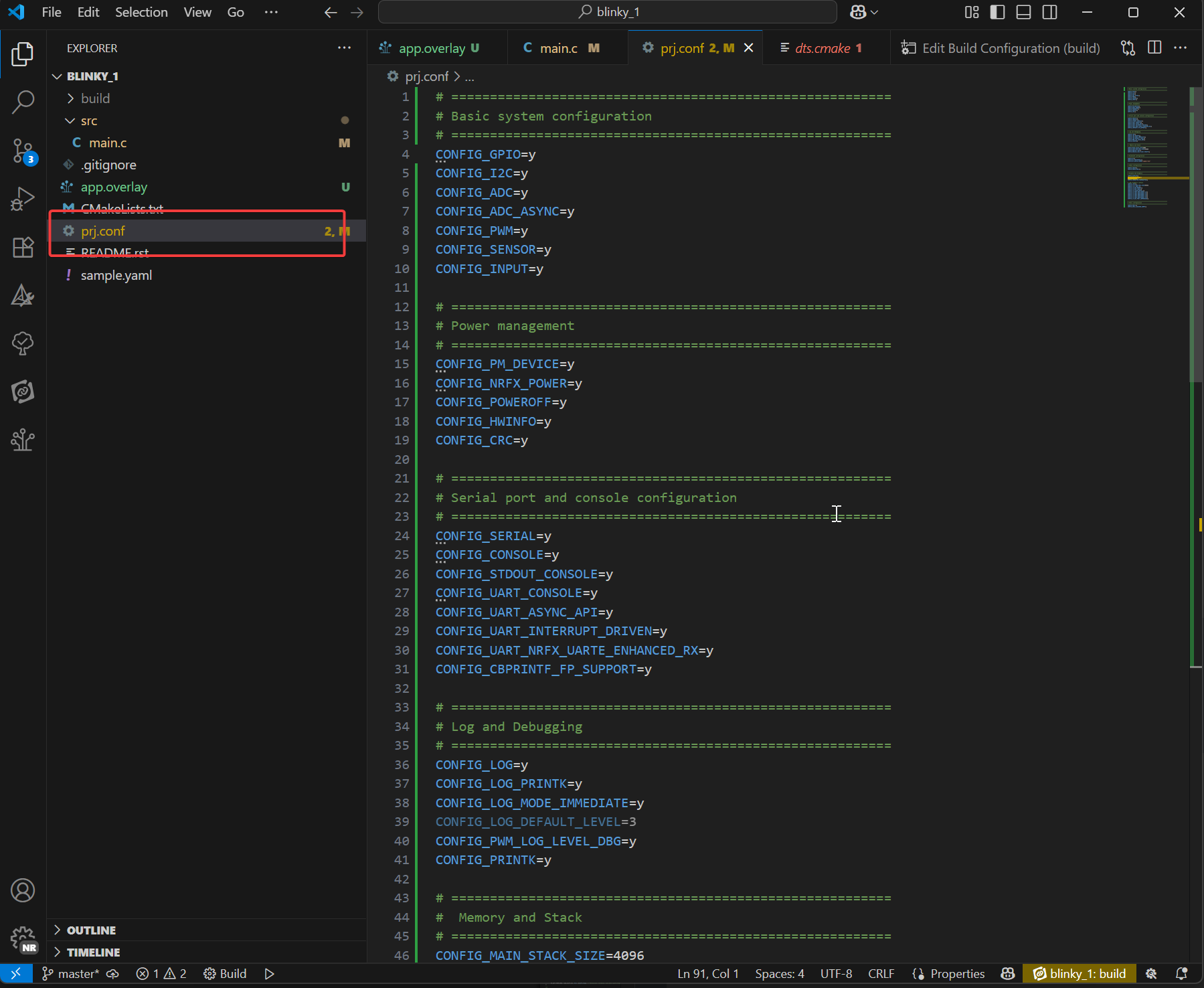
Add the following content under the prj.conf file
- prj.conf is the core configuration file of the Zephyr project. It is managed by the Kconfig system for the selection of software functions during compilation. It determines which drivers (such as ADC, display, Bluetooth), middleware (such as LVGL), and system services (such as logging, memory management) are included in the firmware, and sets their behavior parameters (such as log level, heap size),finally press Ctrl + S to save.
prj.conf code
# =========================================================
# Basic system configuration
# =========================================================
CONFIG_GPIO=y
CONFIG_I2C=y
CONFIG_ADC=y
CONFIG_ADC_ASYNC=y
CONFIG_PWM=y
CONFIG_SENSOR=y
CONFIG_INPUT=y

# =========================================================
# Power management
# =========================================================
CONFIG_PM_DEVICE=y
CONFIG_NRFX_POWER=y
CONFIG_POWEROFF=y
CONFIG_HWINFO=y
CONFIG_CRC=y

# =========================================================
# Serial port and console configuration
# =========================================================
CONFIG_SERIAL=y
CONFIG_CONSOLE=y
CONFIG_STDOUT_CONSOLE=y
CONFIG_UART_CONSOLE=y
CONFIG_UART_ASYNC_API=y
CONFIG_UART_INTERRUPT_DRIVEN=y
CONFIG_UART_NRFX_UARTE_ENHANCED_RX=y
CONFIG_CBPRINTF_FP_SUPPORT=y

# =========================================================
# Log and Debugging
# =========================================================
CONFIG_LOG=y
CONFIG_LOG_PRINTK=y
CONFIG_LOG_MODE_IMMEDIATE=y
CONFIG_LOG_DEFAULT_LEVEL=3
CONFIG_PWM_LOG_LEVEL_DBG=y
CONFIG_PRINTK=y

# =========================================================
#  Memory and Stack
# =========================================================
CONFIG_MAIN_STACK_SIZE=4096
CONFIG_HEAP_MEM_POOL_SIZE=16384
CONFIG_NEWLIB_LIBC=y
CONFIG_NEWLIB_LIBC_FLOAT_PRINTF=y

# =========================================================
# Bluetooth configuration
# =========================================================
CONFIG_BT=y
CONFIG_BT_PERIPHERAL=y
CONFIG_BT_DEVICE_NAME="zephyr-ble"

# =========================================================
# Audio configuration
# =========================================================
CONFIG_AUDIO=y
CONFIG_AUDIO_DMIC=y

# =========================================================
# Display and Graphics
# =========================================================
CONFIG_DISPLAY=y
CONFIG_MIPI_DBI_SPI=y
CONFIG_SSD1306=y
CONFIG_CHARACTER_FRAMEBUFFER=y

# LVGL Graphics Library
CONFIG_LVGL=y
CONFIG_LV_Z_MEM_POOL_SIZE=49152
CONFIG_LV_Z_SHELL=y
CONFIG_LV_USE_MONKEY=y
CONFIG_LV_USE_LABEL=y
CONFIG_LV_COLOR_DEPTH_1=y
CONFIG_LV_FONT_MONTSERRAT_12=y
CONFIG_LV_FONT_MONTSERRAT_14=y
CONFIG_LV_FONT_MONTSERRAT_16=y
CONFIG_LV_FONT_MONTSERRAT_18=y
CONFIG_LV_FONT_MONTSERRAT_24=y
CONFIG_LV_USE_FONT_COMPRESSED=y

# =========================================================
# Shell configuration
# =========================================================
CONFIG_SHELL=y
CONFIG_SHELL_BACKEND_DUMMY=y
Core Code
#include <inttypes.h>
#include <stddef.h>
#include <stdint.h>
#include <zephyr/device.h>
#include <zephyr/devicetree.h>
#include <zephyr/drivers/regulator.h>
#include <zephyr/drivers/adc.h>
#include <zephyr/kernel.h>


#if !DT_NODE_EXISTS(DT_PATH(zephyr_user)) || \
 !DT_NODE_HAS_PROP(DT_PATH(zephyr_user), io_channels)
#error "No suitable devicetree overlay specified"
#endif

#define DT_SPEC_AND_COMMA(node_id, prop, idx) \
 ADC_DT_SPEC_GET_BY_IDX(node_id, idx),

/* Data of ADC io-channels specified in devicetree. */
static const struct adc_dt_spec adc_channels[] = {
 DT_FOREACH_PROP_ELEM(DT_PATH(zephyr_user), io_channels,
       DT_SPEC_AND_COMMA)};

static const struct device *const vbat_reg = DEVICE_DT_GET(DT_NODELABEL(vbat_pwr));

int main(void)
{
 int err;
 uint16_t buf;
 int32_t val_mv;
 struct adc_sequence sequence = {
  .buffer = &buf,
  /* buffer size in bytes, not number of samples */
  .buffer_size = sizeof(buf),
 };

 regulator_enable(vbat_reg);
 k_sleep(K_MSEC(100));

 /* Configure channels individually prior to sampling. */
 if (!adc_is_ready_dt(&adc_channels[7]))
 {
  printf("ADC controller device %s not ready\n", adc_channels[7].dev->name);
  return 0;
 }

 err = adc_channel_setup_dt(&adc_channels[7]);
 if (err < 0)
 {
  printf("Could not setup channel #7 (%d)\n", err);
  return 0;
 }

 (void)adc_sequence_init_dt(&adc_channels[7], &sequence);

 err = adc_read_dt(&adc_channels[7], &sequence);
 if (err < 0)
 {
  printf("Could not read (%d)\n", err);
  return 0;
 }

 /*
  * If using differential mode, the 16 bit value
  * in the ADC sample buffer should be a signed 2's
  * complement value.
  */
 if (adc_channels[7].channel_cfg.differential)
 {
  val_mv = (int32_t)((int16_t)buf);
 }
 else
 {
  val_mv = (int32_t)buf;
 }
 err = adc_raw_to_millivolts_dt(&adc_channels[7],
           &val_mv);
 /* conversion to mV may not be supported, skip if not */
 if (err < 0)
 {
  printf(" value in mV not available\n");
 }
 else
 {
  printf("bat vol = %" PRId32 " mV\n", val_mv * 2);
 }

 regulator_disable(vbat_reg);
 return 0;
}
Resources
Seeed Studio XIAO nRF54L15
Hardware Design
- 📄[Datasheet] Nordic nRF54L15 Datasheet
- 📄[Schematic] XIAO nRF54L15 Schematic
- 🗃️[PCB Design Files] XIAO nRF54L15 KiCad Project
- 🗃️[PCB Design Libraries]
- 📄[Pinout Diagram] XIAO nRF54L15 Pinout Sheet
Mechanical
- 🗃️[2D Dimensions] XIAO nRF54L15 Dimension in DXF
Seeed Studio XIAO nRF54L15 Sense
Hardware Design
- 📄[Datasheet] Nordic nRF54L15 Datasheet
- 📄[Schematic] XIAO nRF54L15 Sense Schematic
- 🗃️[PCB Design Files]
- 🗃️[PCB Design Libraries]
- 🗃️[Pinout Diagram] XIAO nRF54L15 Sense Pinout Sheet
Mechanical
- 📄[2D Dimensions] XIAO nRF54L15 Sense Dimension in DXF
- 🗃️[3D Dimensions] XIAO nRF54L15 Sense 3D imensions
Tech Support & Product Discussion
Thank you for choosing our products! We are here to provide you with different support to ensure that your experience with our products is as smooth as possible. We offer several communication channels to cater to different preferences and needs.