MicroPython for Seeed Studio XIAO nRF54L15
Understanding MicroPython
This tutorial aims to introduce how to use MicroPython on Thonny based on XIAO nRF54L15.
MicroPython is a Python interprer with a partial native code compilation feature. It provides a subset of Python 3.5 features, implemented for embedded processors and constrained systems. It is different from CPython and you can read more about the differences here.If you need more interesting collections, you can check here
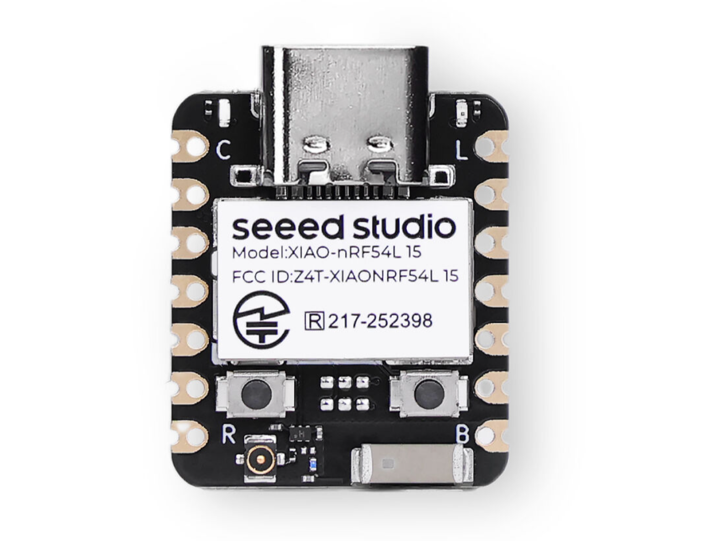
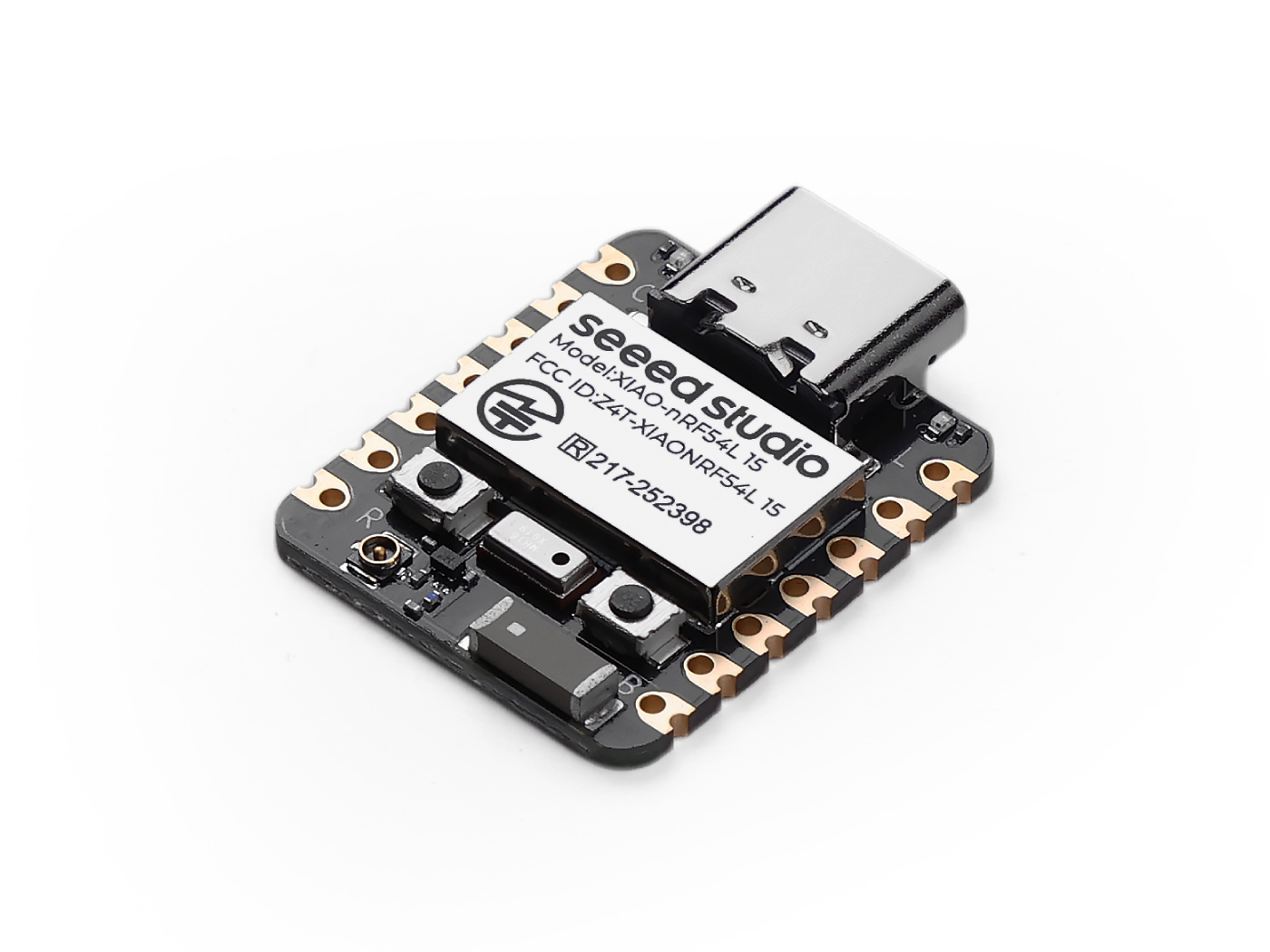
Prepare Hardware.
| Seeed Studio XIAO nRF54L15 | Seeed Studio XIAO nRF54L15 Sense | Seeed Studio XIAO Debug Mate |
|---|---|---|
 |  |  |
Install Thonny IDE
Choose the appropriate version for installation. Here, I am installing it on a Windows system, so I have selected the Windows version.
Follow the instructions for the desired Python version.
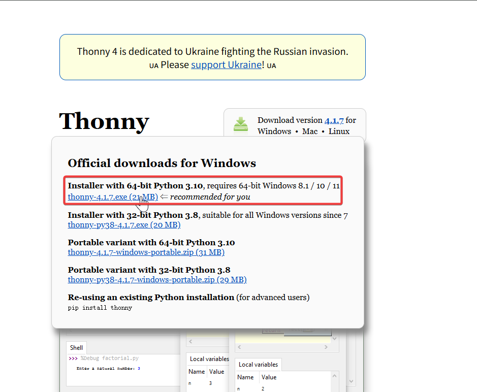
Then, simply follow the default steps for configuration.
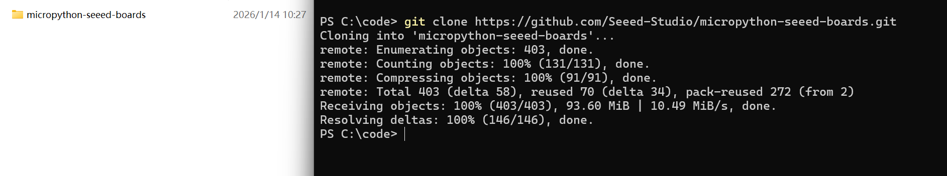
Download the repository
Clone it to the local machine, and then remember the path where this XIAO nRF54L15's MicroPython is stored. This path will be used later.
git clone https://github.com/Seeed-Studio/micropython-seeed-boards.git
Upload board file
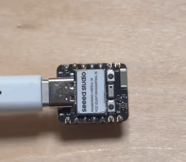
Step 0. Connect XIAO NRF54L15 to the computer using a USB cable
Step 1. Flash the MicroPython firmware for XIAO nRF54L15
-
Download the firmware package and extract it to the appropriate location. Then click on flash.bat, and it will automatically flash the firmware for you.
[Firmware] XIAO nRF54L15 MicroPython Firmware
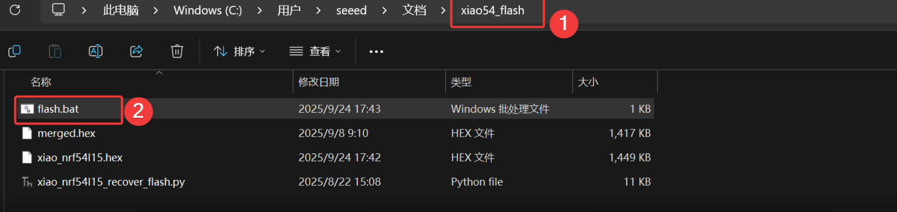
The result is as follows
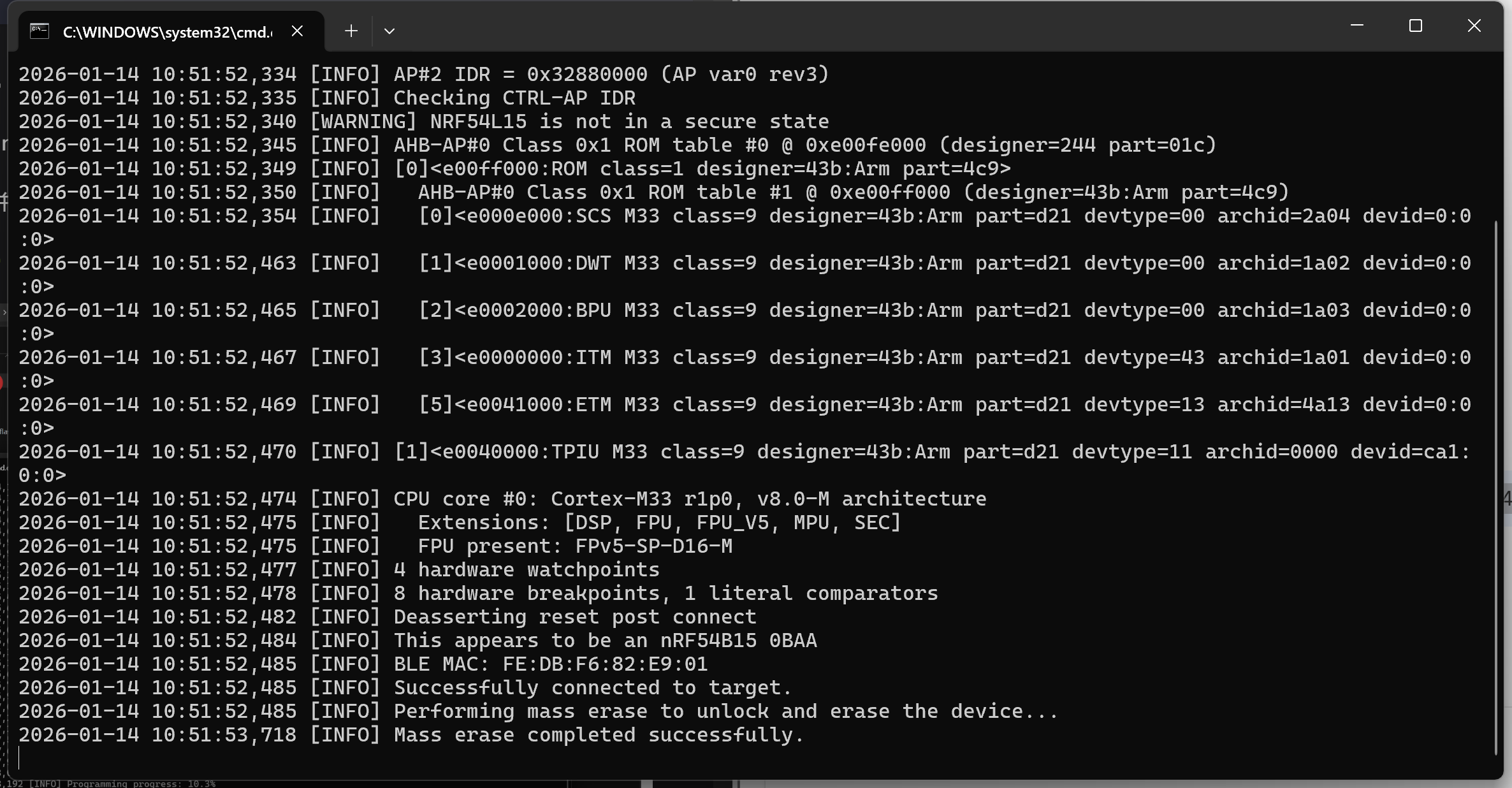
This script has preconfigured flashing toolchain commands. If you are using it for the first time, it may take a little time.It will automatically crash after downloading. If the XIAO NRF54L15 is not plugged in, a '200' error will occur during flashing.
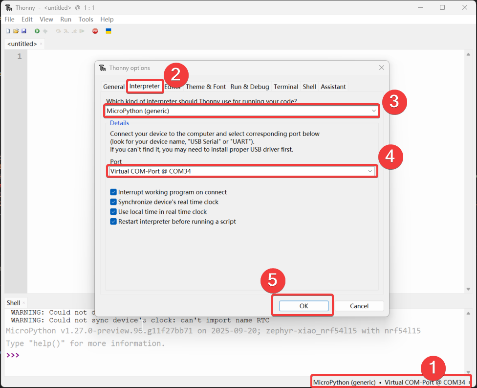
Step 2. Open Thonny IDE, then click the bottom right corner of the interface to configure the interpreter options. Select MicroPython (generic) and Port
Step 3. Upload the boards file
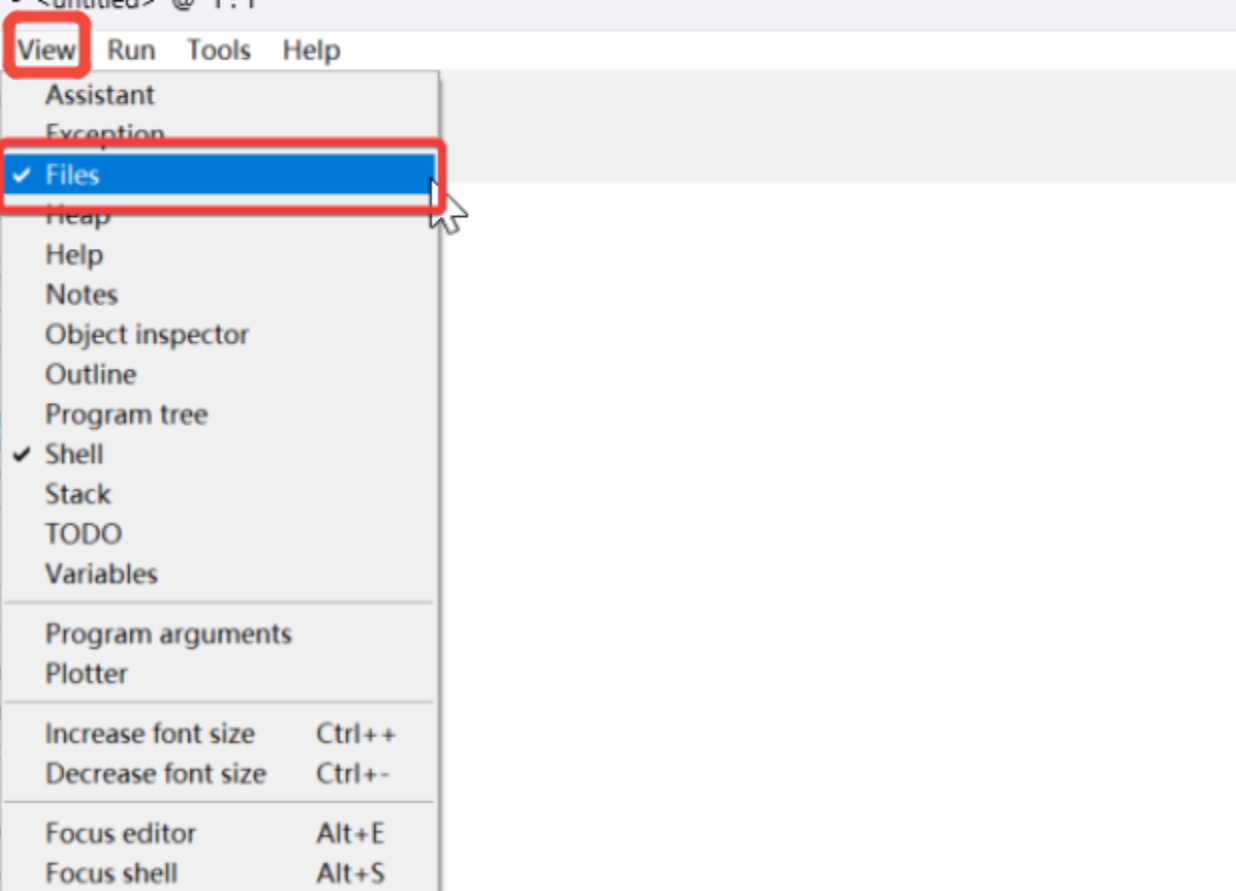
- Open the “view”, select "File", and the file manager path will be displayed on the left sidebar.
- Open the path of the cloned or downloaded file, and open
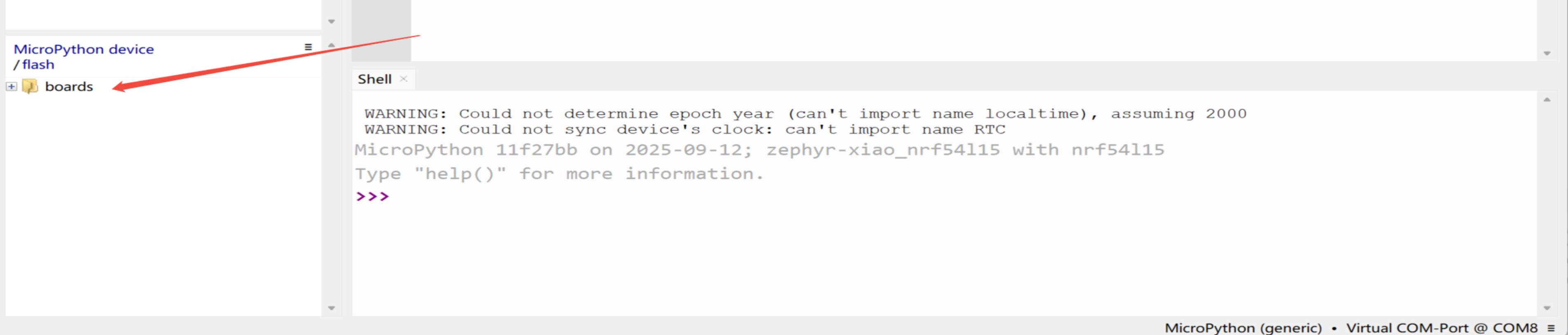
micropython-seeed-boards\examples-Right-click on the "boards" folder and upload it to the flash. Then, you will be able to see the uploaded file on the MicroPython device/flash.
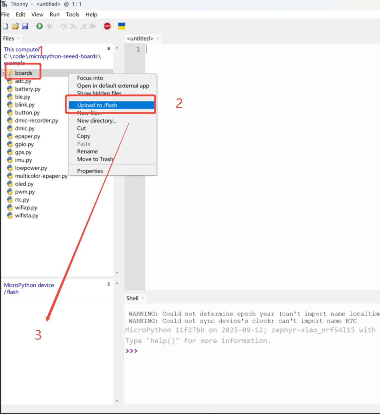
When normal, an icon will appear at position '3'
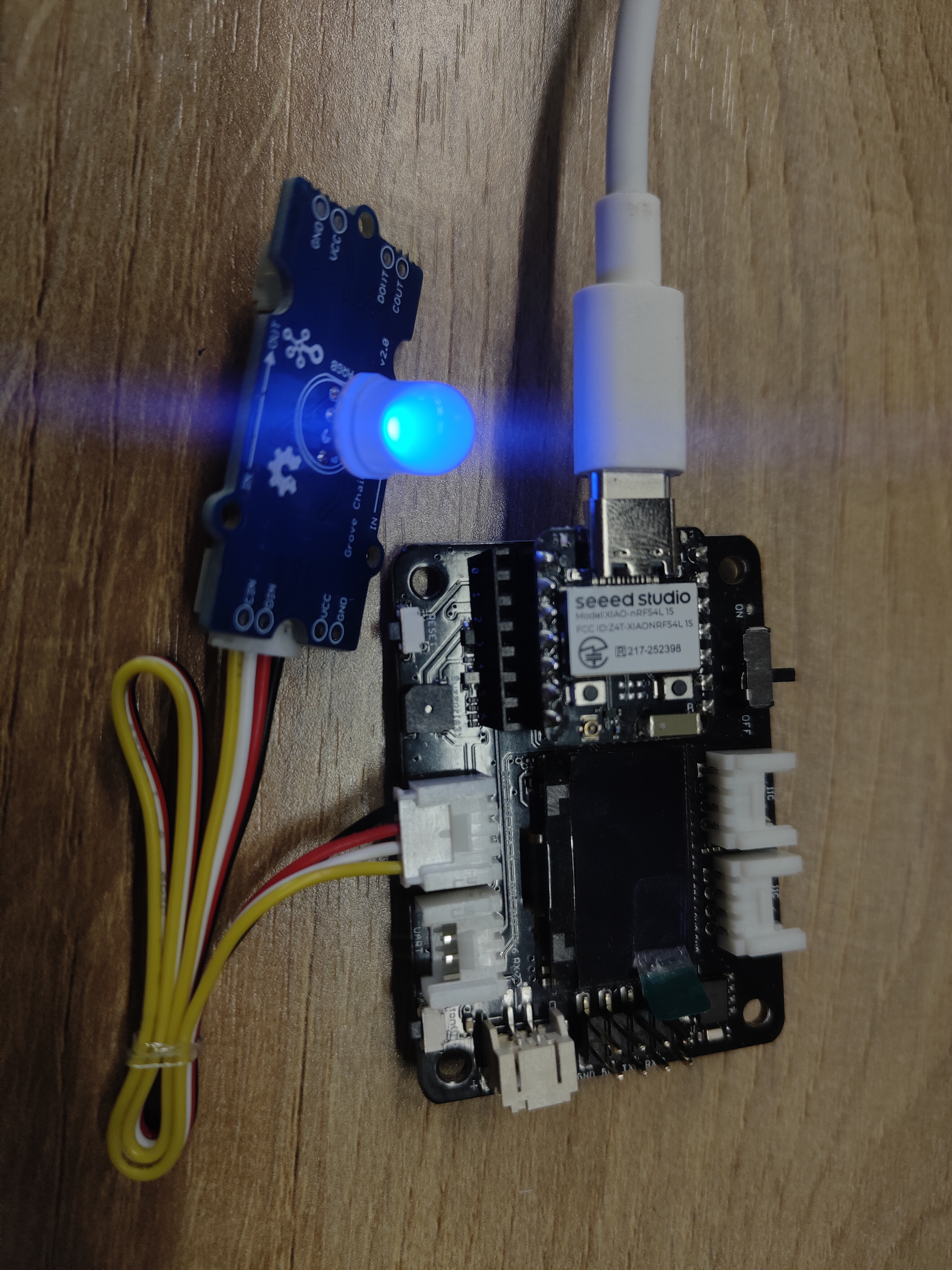
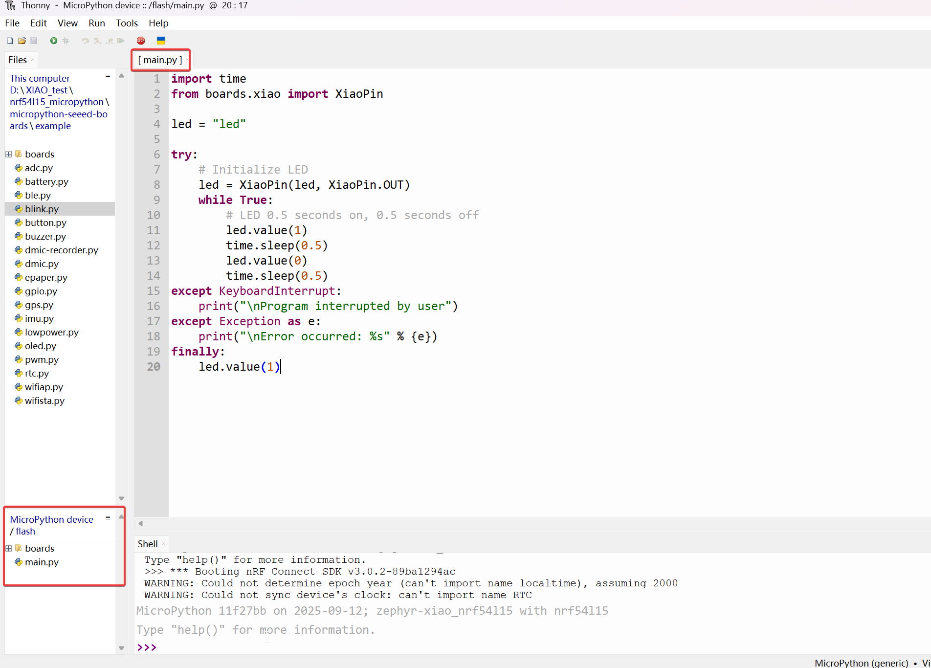
Step 4. Turn on the LED
Open a new file (XX.py) or go to the start page, then copy the code and press F5 to run it.
import time
from boards.xiao import XiaoPin

led = "led"

try:
    # Initialize LED
    led = XiaoPin(led, XiaoPin.OUT)
    while True:
        # LED 0.5 seconds on, 0.5 seconds off
        led.value(1)
        time.sleep(0.5)
        led.value(0)
        time.sleep(0.5)
except KeyboardInterrupt:
    print("\nProgram interrupted by user")
except Exception as e:
    print("\nError occurred: %s" % {e})
finally:
    led.value(1)
The result is as follows:
Digital
Hardware
| Seeed Studio XIAO nRF54L15 Sense | Seeed Studio Expansion Base for XIAO with Grove OLED | Grove - Relay |
|---|---|---|
|  |  |
Software
from machine import Pin
from boards.xiao_nrf54l15 import xiao_nrf54l15 as xiao

# Define a function to get the GPIO information corresponding to pin A0
def get_a0_pin():
    # Get the information of pin A0 through the pin method of the xiao module
    # According to the definition in xiao_nrf54l15.py, A0 corresponds to digital pin 0
    pin_info = xiao.pin(0)  # Get the information of digital pin 0, the return value is a tuple, such as ("gpio1", 4)
    return pin_info

# Define a function to set pin A0 to high level
def set_a0_high():
    # Get the GPIO information of pin A0
    gpio_port, gpio_pin = get_a0_pin()  # Get the port and pin number
    # Create a Pin object, specify the pin as output mode, and set it to high level
    pin = Pin((gpio_port, gpio_pin), Pin.OUT)  # Initialize the pin as output mode
    pin.value(1)  # Set the pin to high level

# Main program
if __name__ == "__main__":
    set_a0_high()  # Call the function to set pin A0 to high level
    print("Pin A0 has been set to high level")  # Output prompt information
Code Explain: This code has four parts, such as importing modules, a function to get the GPIO information of pin A0, a function to set pin A0 to high level, and the main function, where in the main program it calls the operation to set pin A0 to high level.
Result
Analog
Hardware
| Seeed Studio XIAO nRF54L15 Sense | Grove-Variable Color LED | Grove-Rotary Angle Sensor | Seeed Studio Grove Base for XIAO |
|---|---|---|---|
|  |  |  |
Software
import time
from boards.xiao import XiaoPin, XiaoADC, XiaoPWM

adc = 0    #D0
pwm = 1    #D1

try:
    # Initialize ADC for potentiometer
    adc = XiaoADC(adc)
    # Initialize PWM for LED control
    pwm = XiaoPWM(pwm)
    FREQ = 1000
    PERIOD_NS = 1000000
    pwm.init(freq=FREQ, duty_ns=0)
    # Potentiometer parameters
    MIN_VOLTAGE = 0.0
    MAX_VOLTAGE = 3.3
    DEAD_ZONE = 0.05
    last_duty = -1
    while True:
        # Read ADC voltage value
        voltage = adc.read_uv() / 1000000

        # Ensure voltage is within valid range
        if voltage < MIN_VOLTAGE:
            voltage = MIN_VOLTAGE
        elif voltage > MAX_VOLTAGE:
            voltage = MAX_VOLTAGE

        duty_percent = (voltage - MIN_VOLTAGE) / (MAX_VOLTAGE - MIN_VOLTAGE)

        # Apply dead zone to prevent tiny fluctuations
        if abs(duty_percent - last_duty) < DEAD_ZONE / 100:
            time.sleep(0.05)
            continue

        # Calculate duty cycle time (nanoseconds)
        duty_ns = int(duty_percent * PERIOD_NS)

        # Set PWM duty cycle
        pwm.duty_ns(duty_ns)

        # Print current status
        print("Voltage: {:.2f}V, Duty Cycle: {:.1f}%".format(voltage, duty_percent * 100))

        # Update last duty cycle value
        last_duty = duty_percent

        # Short delay
        time.sleep(0.05)
except KeyboardInterrupt:
    print("\nProgram interrupted by user")
except Exception as e:
    print("\nError occurred: %s" % {e})
finally:
    pwm.deinit()
Code Explain: This code can be divided into four parts:
- importing modules:including the time module for delay operations, as well as the XiaoADC and XiaoPWM modules
- initializing the hardware:defining the ADC and PWM pins, and initializing the ADC to read the voltage of the potentiometer, and initializing the PWM to control the LED brightness.
- The main program logic:in an infinite loop, reads the voltage of the potentiometer, converts it to a PWM duty cycle, and adjusts the LED brightness according to the voltage.
- Exception handling and cleanup:capturing user interruptions (such as pressing Ctrl+C) and other exceptions to ensure the program exits safely.
Result
I2C
Hardware
| Seeed Studio XIAO nRF54L15 Sense | Seeed Studio Expansion Board Base for XIAO |
|---|---|
| |
Software
import time
from boards.xiao import XiaoI2C

sda = 4        #D4
scl = 5        #D5
i2c = "i2c0"
frq = 400000
i2c = XiaoI2C(i2c, sda, scl, frq)

# --- SSD1306 I2C address and command definitions ---
SSD1306_I2C_ADDR = 0x3C
SSD1306_SET_CONTRAST = 0x81
SSD1306_DISPLAY_ALL_ON_RESUME = 0xA4
SSD1306_DISPLAY_ALL_ON = 0xA5
SSD1306_NORMAL_DISPLAY = 0xA6
SSD1306_INVERT_DISPLAY = 0xA7
SSD1306_DISPLAY_OFF = 0xAE
SSD1306_DISPLAY_ON = 0xAF
SSD1306_SET_DISPLAY_OFFSET = 0xD3
SSD1306_SET_COM_PINS = 0xDA
SSD1306_SET_VCOM_DETECT = 0xDB
SSD1306_SET_DISPLAY_CLOCK_DIV = 0xD5
SSD1306_SET_PRECHARGE = 0xD9
SSD1306_SET_MULTIPLEX = 0xA8
SSD1306_SET_LOW_COLUMN = 0x00
SSD1306_SET_HIGH_COLUMN = 0x10
SSD1306_SET_START_LINE = 0x40
SSD1306_MEMORY_MODE = 0x20
SSD1306_COLUMN_ADDR = 0x21
SSD1306_PAGE_ADDR = 0x22
SSD1306_COM_SCAN_INC = 0xC0
SSD1306_COM_SCAN_DEC = 0xC8
SSD1306_SEG_REMAP = 0xA0
SSD1306_CHARGE_PUMP = 0x8D

# Display dimensions
SSD1306_WIDTH = 128
SSD1306_HEIGHT = 64
SSD1306_PAGES = 8

# Basic 8x8 font
font_data = {
    ' ': [0x00,0x00,0x00,0x00,0x00,0x00,0x00,0x00],
    'A': [0x18,0x24,0x42,0x7E,0x42,0x42,0x42,0x00],
    'B': [0x7C,0x42,0x42,0x7C,0x42,0x42,0x7C,0x00],
    'C': [0x3C,0x42,0x40,0x40,0x40,0x42,0x3C,0x00],
    'D': [0x78,0x44,0x42,0x42,0x42,0x44,0x78,0x00],
    'E': [0x7C,0x40,0x40,0x78,0x40,0x40,0x7C,0x00],
    'F': [0x7C,0x40,0x40,0x78,0x40,0x40,0x40,0x00],
    'G': [0x3C,0x42,0x40,0x4E,0x42,0x42,0x3C,0x00],
    'H': [0x44,0x44,0x44,0x7C,0x44,0x44,0x44,0x00],
    'I': [0x38,0x10,0x10,0x10,0x10,0x10,0x38,0x00],
    'J': [0x1C,0x08,0x08,0x08,0x08,0x48,0x30,0x00],
    'K': [0x44,0x48,0x50,0x60,0x50,0x48,0x44,0x00],
    'L': [0x40,0x40,0x40,0x40,0x40,0x40,0x7C,0x00],
    'M': [0x42,0x66,0x5A,0x42,0x42,0x42,0x42,0x00],
    'N': [0x42,0x62,0x52,0x4A,0x46,0x42,0x42,0x00],
    'O': [0x3C,0x42,0x42,0x42,0x42,0x42,0x3C,0x00],
    'P': [0x7C,0x42,0x42,0x7C,0x40,0x40,0x40,0x00],
    'Q': [0x3C,0x42,0x42,0x42,0x4A,0x44,0x3A,0x00],
    'R': [0x7C,0x42,0x42,0x7C,0x48,0x44,0x42,0x00],
    'S': [0x3C,0x42,0x40,0x3C,0x02,0x42,0x3C,0x00],
    'T': [0x7C,0x10,0x10,0x10,0x10,0x10,0x10,0x00],
    'U': [0x42,0x42,0x42,0x42,0x42,0x42,0x3C,0x00],
    'V': [0x42,0x42,0x42,0x42,0x42,0x24,0x18,0x00],
    'W': [0x42,0x42,0x42,0x42,0x5A,0x66,0x42,0x00],
    'X': [0x42,0x24,0x18,0x18,0x18,0x24,0x42,0x00],
    'Y': [0x44,0x44,0x28,0x10,0x10,0x10,0x10,0x00],
    'Z': [0x7E,0x04,0x08,0x10,0x20,0x40,0x7E,0x00],
    '0': [0x3C,0x42,0x46,0x4A,0x52,0x62,0x3C,0x00],
    '1': [0x10,0x30,0x10,0x10,0x10,0x10,0x38,0x00],
    '2': [0x3C,0x42,0x02,0x0C,0x30,0x40,0x7E,0x00],
    '3': [0x3C,0x42,0x02,0x1C,0x02,0x42,0x3C,0x00],
    '4': [0x08,0x18,0x28,0x48,0x7E,0x08,0x08,0x00],
    '5': [0x7E,0x40,0x7C,0x02,0x02,0x42,0x3C,0x00],
    '6': [0x1C,0x20,0x40,0x7C,0x42,0x42,0x3C,0x00],
    '7': [0x7E,0x42,0x04,0x08,0x10,0x10,0x10,0x00],
    '8': [0x3C,0x42,0x42,0x3C,0x42,0x42,0x3C,0x00],
    '9': [0x3C,0x42,0x42,0x3E,0x02,0x04,0x38,0x00],
    '!': [0x10,0x10,0x10,0x10,0x10,0x00,0x10,0x00],
    '?': [0x3C,0x42,0x02,0x0C,0x10,0x00,0x10,0x00],
    '.': [0x00,0x00,0x00,0x00,0x00,0x00,0x10,0x00],
    ',': [0x00,0x00,0x00,0x00,0x00,0x10,0x10,0x20],
    ':': [0x00,0x10,0x00,0x00,0x00,0x10,0x00,0x00],
    ';': [0x00,0x10,0x00,0x00,0x00,0x10,0x10,0x20],
    '-': [0x00,0x00,0x00,0x7C,0x00,0x00,0x00,0x00],
    '_': [0x00,0x00,0x00,0x00,0x00,0x00,0x7E,0x00],
    '+': [0x00,0x10,0x10,0x7C,0x10,0x10,0x00,0x00],
    '*': [0x00,0x24,0x18,0x7E,0x18,0x24,0x00,0x00],
    '/': [0x02,0x04,0x08,0x10,0x20,0x40,0x00,0x00],
    '\\': [0x40,0x20,0x10,0x08,0x04,0x02,0x00,0x00],
    '=': [0x00,0x00,0x7E,0x00,0x7E,0x00,0x00,0x00],
    '\'': [0x10,0x10,0x20,0x00,0x00,0x00,0x00,0x00],
    '"': [0x24,0x24,0x00,0x00,0x00,0x00,0x00,0x00],
    '(': [0x08,0x10,0x20,0x20,0x20,0x10,0x08,0x00],
    ')': [0x20,0x10,0x08,0x08,0x08,0x10,0x20,0x00],
    '[': [0x1C,0x10,0x10,0x10,0x10,0x10,0x1C,0x00],
    ']': [0x38,0x08,0x08,0x08,0x08,0x08,0x38,0x00],
    '{': [0x0C,0x10,0x10,0x60,0x10,0x10,0x0C,0x00],
    '}': [0x30,0x08,0x08,0x06,0x08,0x08,0x30,0x00],
    '<': [0x08,0x10,0x20,0x40,0x20,0x10,0x08,0x00],
    '>': [0x20,0x10,0x08,0x04,0x08,0x10,0x20,0x00],
    '|': [0x10,0x10,0x10,0x10,0x10,0x10,0x10,0x00],
    '@': [0x3C,0x42,0x5A,0x5A,0x5C,0x40,0x3C,0x00],
    '#': [0x24,0x24,0x7E,0x24,0x7E,0x24,0x24,0x00],
    '$': [0x10,0x3C,0x50,0x3C,0x12,0x3C,0x10,0x00],
    '%': [0x62,0x64,0x08,0x10,0x26,0x46,0x00,0x00],
    '^': [0x10,0x28,0x44,0x00,0x00,0x00,0x00,0x00],
    '&': [0x30,0x48,0x50,0x20,0x54,0x48,0x34,0x00],
    '~': [0x00,0x00,0x34,0x4C,0x00,0x00,0x00,0x00]
}

# --- Helper functions ---

# Write a single command byte to SSD1306 via I2C
def ssd1306_write_command(cmd):
    i2c.writeto(SSD1306_I2C_ADDR, bytes([0x00, cmd]))

# Write multiple command bytes to SSD1306 via I2C
def ssd1306_write_commands(cmds):
    data = bytearray([0x00] + list(cmds))
    i2c.writeto(SSD1306_I2C_ADDR, data)

# Write display data bytes to SSD1306 via I2C
def ssd1306_write_data(data):
    buffer = bytearray(len(data) + 1)
    buffer[0] = 0x40
    buffer[1:] = data
    i2c.writeto(SSD1306_I2C_ADDR, buffer)

# Clear the entire SSD1306 display
def ssd1306_clear():
    ssd1306_write_commands(bytearray([SSD1306_COLUMN_ADDR, 0, SSD1306_WIDTH - 1]))
    ssd1306_write_commands(bytearray([SSD1306_PAGE_ADDR, 0, SSD1306_PAGES - 1]))

    empty_data = bytearray(SSD1306_WIDTH)
    for _ in range(SSD1306_PAGES):
        ssd1306_write_data(empty_data)
    ssd1306_write_commands([SSD1306_COLUMN_ADDR, 0, SSD1306_WIDTH - 1])

# Initialize SSD1306 display with recommended settings
def ssd1306_init():
    commands = [
        bytearray([SSD1306_DISPLAY_OFF]),
        bytearray([SSD1306_SET_DISPLAY_CLOCK_DIV, 0x80]),
        bytearray([SSD1306_SET_MULTIPLEX, SSD1306_HEIGHT - 1]),
        bytearray([SSD1306_SET_DISPLAY_OFFSET, 0x00]),
        bytearray([SSD1306_SET_START_LINE | 0x00]),
        bytearray([SSD1306_CHARGE_PUMP, 0x14]),
        bytearray([SSD1306_MEMORY_MODE, 0x00]),
        bytearray([SSD1306_SEG_REMAP | 0x01]),
        bytearray([SSD1306_COM_SCAN_DEC]),
        bytearray([SSD1306_SET_COM_PINS, 0x12]),
        bytearray([SSD1306_SET_CONTRAST, 0xCF]),
        bytearray([SSD1306_SET_PRECHARGE, 0xF1]),
        bytearray([SSD1306_SET_VCOM_DETECT, 0x40]),
        bytearray([SSD1306_DISPLAY_ALL_ON_RESUME]),
        bytearray([SSD1306_NORMAL_DISPLAY]),
        bytearray([SSD1306_DISPLAY_ON])
    ]

    for cmd in commands:
        ssd1306_write_commands(cmd)

    ssd1306_clear()
    print("SSD1306 initialized successfully.")
    ssd1306_write_commands([SSD1306_COLUMN_ADDR, 0, SSD1306_WIDTH - 1])

# Draw a string of text at specified column and page (row) on SSD1306
def ssd1306_draw_text(text, x, y):
    ssd1306_write_commands(bytearray([SSD1306_COLUMN_ADDR, x, x + len(text) * 8 - 1]))
    ssd1306_write_commands(bytearray([SSD1306_PAGE_ADDR, y, y + 0]))

    display_data = bytearray()
    for char in text:
        font_bytes = font_data.get(char.upper(), font_data[' '])
        for col in range(7, -1, -1):
            val = 0
            for row in range(8):
                if font_bytes[row] & (1 << col):
                    val |= (1 << row)
            display_data.append(val)

    ssd1306_write_data(display_data)

i2c_addr = i2c.scan()
if SSD1306_I2C_ADDR not in i2c_addr:
    raise Exception("SSD1306 not found on I2C bus")
else:
    print("SSD1306 found on I2C bus: 0x{:02X}".format(SSD1306_I2C_ADDR))

# Initialize display
ssd1306_init()
ssd1306_draw_text("NRF54L15", 30, 2)
ssd1306_draw_text("HELLO WORLD", 20, 4)
Code Explain:
This code initializes and controls an SSD1306 OLED display via I2C communication, defines the display's commands and parameters, and implements functions for clearing the screen, initialization, and displaying text.
-
Import modules and initialize I2C communication: The time module was imported for delay operations, and the XiaoI2C module was imported to initialize I2C communication. The SDA and SCL pins of the I2C were defined, and the I2C frequency was set. Then, a XiaoI2C object was created for communication with I2C devices, such as an OLED display.
-
Define the instructions and parameters of the SSD1306 display: Defines the I2C address of the SSD1306 display and a series of control commands (such as setting contrast, display on/off, etc.). It also defines the display's size parameters (width, height, and number of pages) and a simple 8x8 dot matrix font library for displaying characters on the screen.
-
Define helper function: A series of helper functions are defined for sending commands and data to the SSD1306.
-
Main program logic: First, check if the SSD1306 display is connected to the I2C bus by performing an I2C scan. If the display is found, call the ssd1306_init function to initialize the display. Then, call the ssd1306_draw_text function to display the two lines of text "NRF54L15" and "HELLO WORLD" on the display.
Result
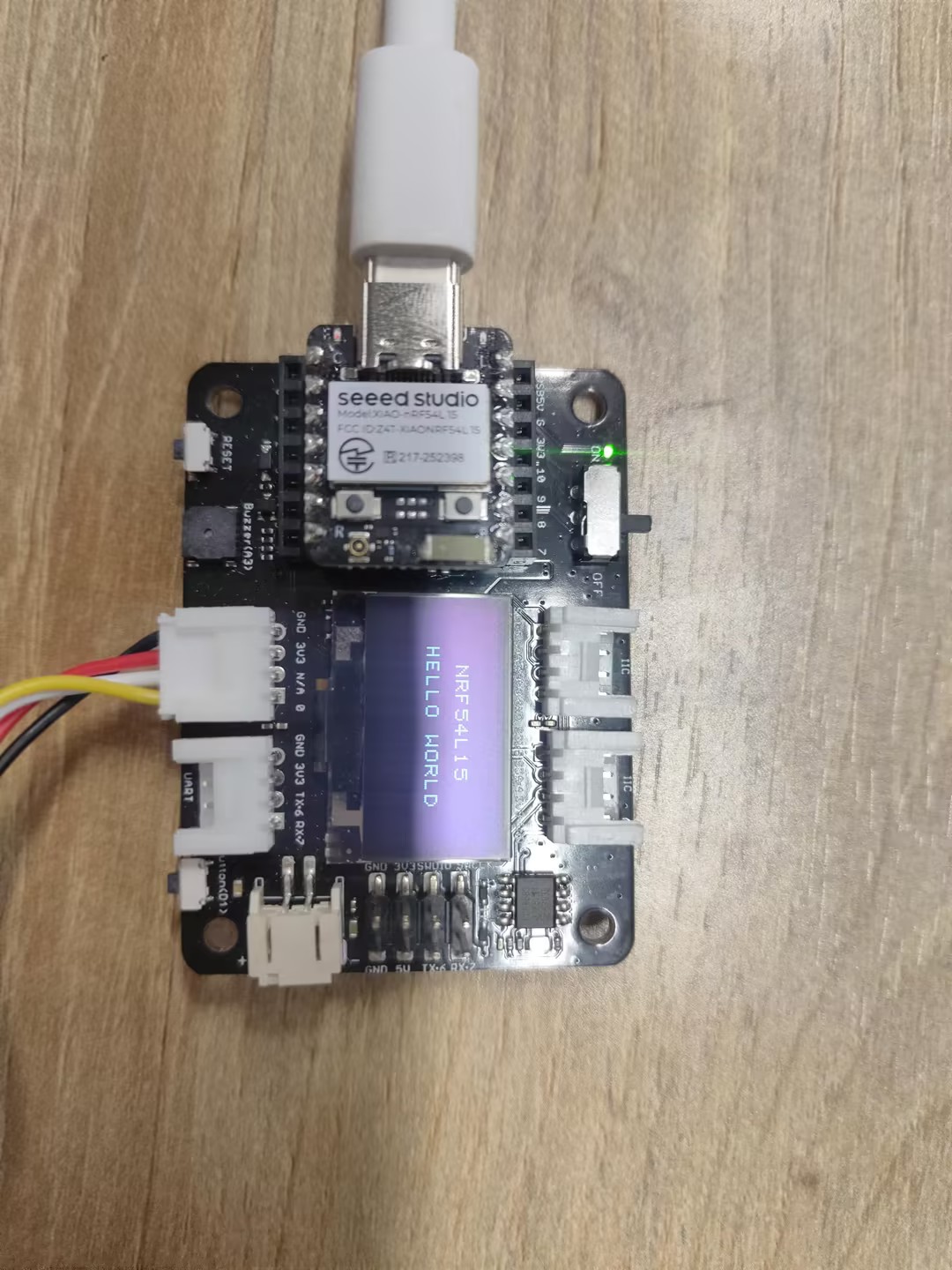
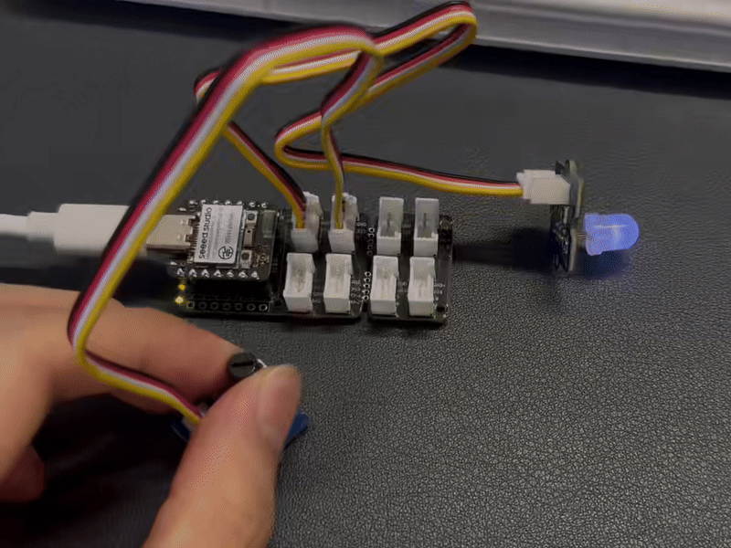
SPI
Hardware
| Seeed Studio XIAO nRF54L15 Sense | ePaper Driver Board for Seeed Studio XIAO |
|---|---|
|  |
Software
import time
from boards.xiao import XiaoPin, XiaoSPI
# -------- Pins & SPI --------
RST = 0; CS = 1; DC = 3; BUSY = 5
sck = 9; mosi = 10; miso = 8; spi_id = "spi0"
RST = XiaoPin(RST, XiaoPin.OUT)
CS = XiaoPin(CS, XiaoPin.OUT)
DC = XiaoPin(DC, XiaoPin.OUT)
BUSY = XiaoPin(BUSY, XiaoPin.IN, XiaoPin.PULL_UP)
spi = XiaoSPI(spi_id, 20_000_000, sck, mosi, miso)
# -------- ePaper basics --------
def reset():
RST.value(0); time.sleep_ms(10)
RST.value(1); time.sleep_ms(10)
def send_command(cmd):
DC.value(0); CS.value(0)
spi.write(bytearray([cmd & 0xFF]))
CS.value(1)
def send_data(data):
DC.value(1); CS.value(0)
if isinstance(data, int):
spi.write(bytearray([data & 0xFF]))
else:
spi.write(data)
CS.value(1)
def wait_until_idle():
# If BUSY = 0, it indicates that the device is busy. You can then switch back to polling.
# while BUSY.value() == 0: time.sleep_ms(1)
time.sleep_ms(1)
def init_display():
reset()
send_command(0x00); send_data(0x1F)
send_command(0x04); time.sleep_ms(100); wait_until_idle()
send_command(0x50); send_data(0x21); send_data(0x07)
def clear_screen():
CS.value(0)
DC.value(0); spi.write(b'\x10'); DC.value(1)
for _ in range(48000): spi.write(b'\xFF')
DC.value(0); spi.write(b'\x13'); DC.value(1)
for _ in range(48000): spi.write(b'\xFF')
DC.value(0); spi.write(b'\x12'); CS.value(1)
wait_until_idle()
# -------- Geometry --------
WIDTH, HEIGHT = 800, 480
BYTES_PER_ROW = WIDTH // 8
linebuf = bytearray(BYTES_PER_ROW)
# -------- Minimal 5x7 glyphs (columns, LSB=top) --------
FONT_W, FONT_H = 5, 7
G = {
' ':[0x00,0x00,0x00,0x00,0x00],
# Digits
'0':[0x3E,0x51,0x49,0x45,0x3E],
'1':[0x00,0x42,0x7F,0x40,0x00],
'2':[0x42,0x61,0x51,0x49,0x46],
'3':[0x21,0x41,0x45,0x4B,0x31],
'4':[0x18,0x14,0x12,0x7F,0x10],
'5':[0x27,0x45,0x45,0x45,0x39],
'6':[0x3C,0x4A,0x49,0x49,0x30],
'7':[0x01,0x71,0x09,0x05,0x03],
'8':[0x36,0x49,0x49,0x49,0x36],
'9':[0x06,0x49,0x49,0x29,0x1E],
# Uppercase
'A':[0x7E,0x11,0x11,0x11,0x7E],
'F':[0x7F,0x09,0x09,0x09,0x01],
'H':[0x7F,0x08,0x08,0x08,0x7F],
'I':[0x00,0x41,0x7F,0x41,0x00],
'L':[0x7F,0x40,0x40,0x40,0x40],
'M':[0x7F,0x02,0x0C,0x02,0x7F],
'O':[0x3E,0x41,0x41,0x41,0x3E],
'P':[0x7F,0x09,0x09,0x09,0x06],
'R':[0x7F,0x09,0x19,0x29,0x46],
'T':[0x01,0x01,0x7F,0x01,0x01],
'X':[0x63,0x14,0x08,0x14,0x63],
'Y':[0x07,0x08,0x70,0x08,0x07],
# Lowercase
'a':[0x20,0x54,0x54,0x54,0x78],
'c':[0x38,0x44,0x44,0x44,0x20],
'e':[0x38,0x54,0x54,0x54,0x18],
'h':[0x7F,0x08,0x04,0x04,0x78],
'i':[0x00,0x44,0x7D,0x40,0x00],
'l':[0x00,0x41,0x7F,0x40,0x00],
'n':[0x7C,0x08,0x04,0x04,0x78],
'o':[0x38,0x44,0x44,0x44,0x38],
'p':[0x7C,0x14,0x14,0x14,0x08],
'r':[0x7C,0x08,0x04,0x04,0x08],
't':[0x04,0x3F,0x44,0x40,0x20],
'y':[0x0C,0x50,0x50,0x50,0x3C],
}
def glyph(ch):
return G.get(ch, G[' '])
# -------- Text helpers --------
def text_size(text, scale=1, spacing=1):
w = 0
for _ in text:
w += (FONT_W * scale + spacing)
if w: w -= spacing
return w, FONT_H * scale
def text_pixel(x, y, text, sx, sy, scale=1, spacing=1):
# Return 0 = Black, 1 = White
if y < sy or y >= sy + FONT_H * scale:
return 1
lx = x - sx
if lx < 0:
return 1
cursor = 0
for ch in text:
cw = FONT_W * scale
if cursor <= lx < cursor + cw:
cx_scaled = lx - cursor
cy_scaled = y - sy
cx = cx_scaled // scale
cy = cy_scaled // scale
col = glyph(ch)[cx]
bit = (col >> cy) & 1
return 0 if bit else 1
cursor += cw + spacing
return 1
# -------- Stream update --------
def epaper_update_lines(lines):
CS.value(0)
# The old picture is completely white.
DC.value(0); spi.write(b'\x10'); DC.value(1)
for _ in range(HEIGHT * BYTES_PER_ROW):
spi.write(b'\xFF')
# New image: Generated row by row
DC.value(0); spi.write(b'\x13'); DC.value(1)
for y in range(HEIGHT):
bi = 0; bitpos = 7; linebuf[:] = b'\x00' * BYTES_PER_ROW
for x in range(WIDTH):
val = 1 # Default white
for (txt, tx, ty, scale) in lines:
if text_pixel(x, y, txt, tx, ty, scale) == 0:
val = 0
break
if val:
linebuf[bi] |= (1 << bitpos) # 1 = white
bitpos -= 1
if bitpos < 0:
bitpos = 7; bi += 1
spi.write(linebuf)
# Redresh
DC.value(0); spi.write(b'\x12'); CS.value(1)
wait_until_idle()
# -------- Main --------
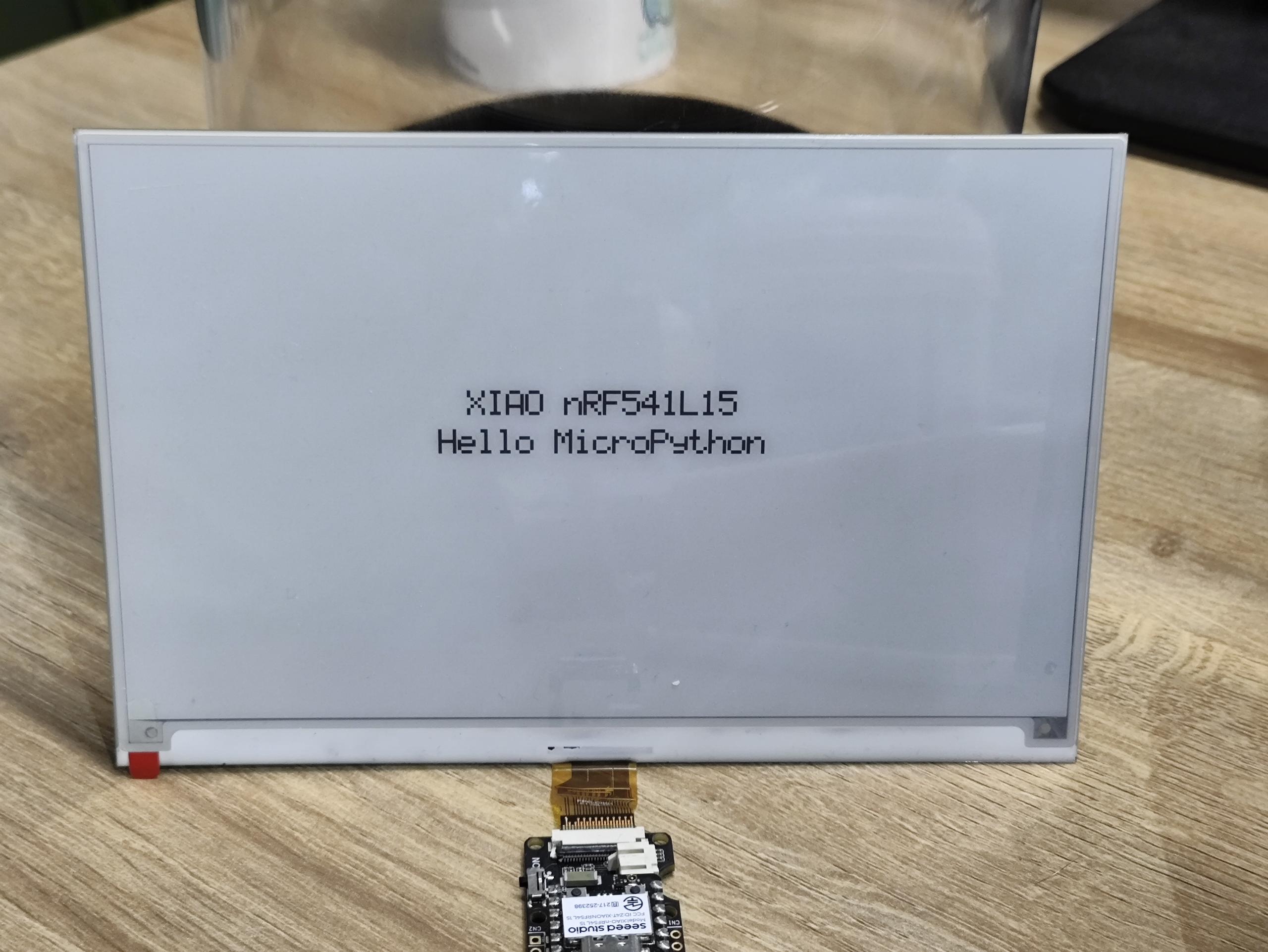
LINE1 = "XIAO nRF541L15"
LINE2 = "Hello MicroPython"
SCALE1 = 3
SCALE2 = 3
def main():
init_display()
clear_screen()
# Centered layout
w1, h1 = text_size(LINE1, SCALE1)
w2, h2 = text_size(LINE2, SCALE2)
total_h = h1 + 12 + h2 # Line spacing: 12 px
y0 = (HEIGHT - total_h) // 2
x1 = (WIDTH - w1) // 2
x2 = (WIDTH - w2) // 2
y1 = y0
y2 = y0 + h1 + 12
lines = [
(LINE1, x1, y1, SCALE1),
(LINE2, x2, y2, SCALE2),
]
epaper_update_lines(lines)
while True:
time.sleep(1_000_000)
if __name__ == "__main__":
main()
Code Explain:
-
Module Import
time: Enables time-related functions such as delays.XiaoPin and XiaoSPI: Imported fromboards.xiao; XiaoPin is used to control GPIO pins, while XiaoSPI handles SPI communication.
-
Pin and SPI Configuration
- Defined specific pins: Reset (RST), Chip Select (CS), Data/Command (DC), and Busy (BUSY).
- Configured SPI-related pins (SCK, MOSI, MISO) and the SPI controller.
- Initialized the working mode (input/output) for all GPIO pins.
- Created an SPI instance with a set frequency of 20 MHz.
-
ePaper Basic Functions
reset(): Executes a hardware reset operation on the display.send_command(cmd): Transmits a single-byte command.send_data(data): Sends data, which can be either a single byte or multiple bytes.wait_until_idle(): Waits for the display to enter an idle state (currently implemented with a simple delay).init_display(): Performs initialization procedures for the display.clear_screen(): Clears the screen, setting it to a full white state.
-
Display Parameters
WIDTH, HEIGHT = 800, 480: Specifies the display's resolution.BYTES_PER_ROW: Indicates the number of bytes needed for each row of pixels.linebuf: A line buffer that temporarily stores pixel data for a single row.
-
Font System
- Defined a simple 5x7 pixel font, stored in the
Gdictionary. glyph(ch): Retrieves the pixel data corresponding to a given character.text_size(): Computes the dimensions of text when displayed at a specified scaling ratio.text_pixel(): Determines if a pixel should be drawn at a specific position (used in text rendering).
- Defined a simple 5x7 pixel font, stored in the
-
Display Update
- epaper_update_lines(lines): The core function for updating the display.
- First, sends data to set a full-white background.
- Then, calculates and transmits new image data row by row.
- Finally, triggers a display refresh to show the new content.
- Supports multi-line text display, where each line can have distinct positions and scaling ratios.
-
main() function
- Initializes the display.
- Calculates the centered position for the text.
- Creates a configuration list for the text lines.
- Calls
epaper_update_lines()to update the display content. - Enters an infinite sleep loop.
Result
Automatically execute the program
If you want your abbreviation program to be able to execute automatically, you can follow these steps:
Step 1. Create a new program file and use Ctrl + S to save it to the flash memory of the MicroPython device, and name it main.py.
Let's take the blink program as an example here
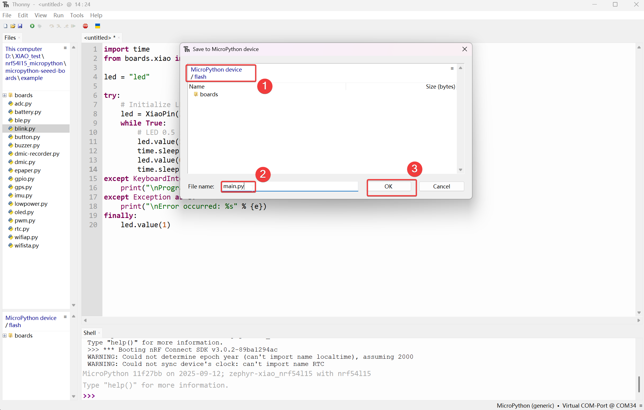
Then it will be displayed under the MicroPython device/flash section.
Step 2. By pressing the on-board Reset button, the automatic execution effect can be achieved.
effct:
FAQ
Bootloader update
If you encounter a situation where you are unable to upload MicroPython programs using Thonny, because the Bootloader used during the factory production was of an older version.
Step 1. Wiring
| OpenOCD / JTAG / SWD | XIAO nRF54L15 |
|---|---|
| 5V | 5V |
| GND | GND |
| SWDIO | SWDIO2 |
| SWDCLK | SWDCLK2 |
| RST | RST |
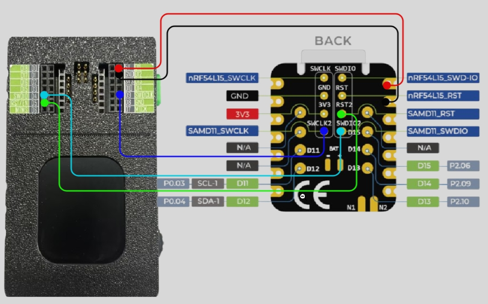
Please make sure that the pin connections are correct to prevent the burning process from failing.
Step 2. Download the firmware burning program
Step 3. Run script
Take the Windows system as an example. Unzip the downloaded file, right-click in the folder and open the terminal. Execute .\xiao_samd11_openocd_flash.bat. If your wiring is correct, the result will be as shown in the following picture.
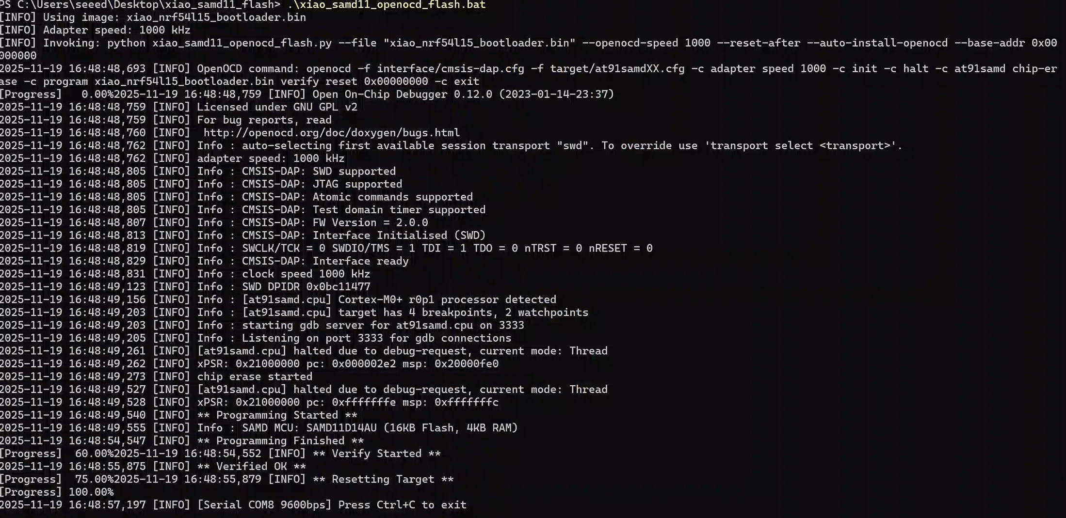
On Mac/Linux systems, you need to change .bat to .sh
Tech Support & Product Discussion
Thank you for choosing our products! We are here to provide you with different support to ensure that your experience with our products is as smooth as possible. We offer several communication channels to cater to different preferences and needs.