Pin Multiplexing with Seeed Studio XIAO nRF54L15 Sense
For ease of use, all of the following examples of pin multiplexing are on PlatformIO. Please click on this link for a configuration and usage guide for the XIAO nRF54L5
Based on VS Code, if you want to use the following case on the nRF Connect SDK, please refer to the provided connection, add the app.overlay file and modify the contents in prj.conf
Onboard Keys
XIAO nRF54L15(Sense) comes equipped with two important physical buttons that play crucial roles in device operation and firmware programming: the Reset Button and the User Button. Understanding their functions is essential for daily use and firmware updates.
Reset Button
The Reset button is used to perform a hard reset operation on the device.
- Functionality:
- Forced Restart: Pressing this button immediately interrupts all current device operations and causes it to restart, similar to a power cycle.
- Resolving Stuck Programs: When the device's running program crashes, enters an infinite loop, or becomes unresponsive, pressing the Reset button is the quickest way to force it back to a normal operating state.
- No Firmware Impact: A reset operation does not erase or alter the firmware already programmed into the device. It simply restarts the currently running application.
User Button
The User button is a versatile, programmable input that offers flexible control within your applications.
Functionality:
-
Customizable Input:Unlike the fixed function of the Reset button, the User button's action is entirely defined by your programmed firmware.
-
Event Triggering: It can be programmed to trigger specific events, control different functionalities, or act as a general-purpose input for your applications.
Digital
Hardware Preparation
| Seeed Studio XIAO nRF54L15 Sense | Seeed Studio Expansion Base for XIAO with Grove OLED | Grove - Relay |
|---|---|---|
 |  |  |
Software Implementation
#include <zephyr/kernel.h>
#include <zephyr/drivers/gpio.h>
#include <zephyr/logging/log.h>


LOG_MODULE_REGISTER(main_app, CONFIG_LOG_DEFAULT_LEVEL);

static const struct gpio_dt_spec button = GPIO_DT_SPEC_GET(DT_ALIAS(sw1), gpios); // Get the button device from the device tree alias
static const struct gpio_dt_spec relay = GPIO_DT_SPEC_GET(DT_ALIAS(relay0), gpios); // Get the relay device from the device tree alias

int main(void)
{
    int ret;

    LOG_INF("Starting Zephyr button and relay example...");

    /* Check if GPIO devices are ready */
    if (!gpio_is_ready_dt(&button)) {
        LOG_ERR("Button device %s is not ready", button.port->name);
        return -1;
    }

    if (!gpio_is_ready_dt(&relay)) {
        LOG_ERR("Relay device %s is not ready", relay.port->name);
        return -1;
    }

    /* Configure button pin as input mode */
    ret = gpio_pin_configure_dt(&button, GPIO_INPUT);
    if (ret != 0) {
        LOG_ERR("Failed to configure %s pin %d (error %d)", button.port->name, button.pin, ret);
        return -1;
    }

    /* Configure relay pin as output mode */
    ret = gpio_pin_configure_dt(&relay, GPIO_OUTPUT_ACTIVE);
    if (ret != 0) {
        LOG_ERR("Failed to configure %s pin %d (error %d)", relay.port->name, relay.pin, ret);
        return -1;
    }

    LOG_INF("Press the button to toggle the relay...");

    while (1) {
        /* Read button state */
        int button_state = gpio_pin_get_dt(&button);

        /* Check if read is successful */
        if (button_state < 0) {
            LOG_ERR("Error reading button pin: %d", button_state);
            return -1;
        }

        if (button_state == 0) { // Button pressed (ACTIVE_LOW)
            gpio_pin_set_dt(&relay, 1); // Turn on relay (high level)
        } else { // Button not pressed
            gpio_pin_set_dt(&relay, 0); // Turn off relay (low level)
        }

        k_msleep(10); /* Short delay to avoid busy looping */
    }
    return 0;
}
Device Tree Configuration
static const struct gpio_dt_spec button = GPIO_DT_SPEC_GET(DT_ALIAS(sw1), gpios);
- This line of code utilizes Zephyr's device tree system to get the button's GPIO device information through an alias named sw1. This approach decouples the code from the specific hardware pins and improves portability.
static const struct gpio_dt_spec relay = GPIO_DT_SPEC_GET(DT_ALIAS(relay0), gpios);
- Again, this line of code gets information about the relay GPIO device named relay0.
Device readiness check
if (!gpio_is_ready_dt(&button)) and if (!gpio_is_ready_dt(&relay))
- Before the program starts performing any operations, the code checks if the button and relay devices are successfully initialized and ready. This is a best practice in Zephyr driver programming and prevents the program from crashing if the devices are not properly configured.
Pin Configuration
gpio_pin_configure_dt(&button, GPIO_INPUT);
- This line of code configures the button's GPIO pin to input mode. This is a necessary step to read the level of the pin, and the program will monitor the voltage level of the pin to determine if the button is pressed.
gpio_pin_configure_dt(&relay, GPIO_OUTPUT_ACTIVE);
- This line of code configures the relay's GPIO pin to output mode. the
GPIO_OUTPUT_ACTIVEflag usually indicates that the pin will be active after configuration in preparation for controlling the relay.
Main Loop Logic
while (1): The code enters an infinite loop that continuously performs the following actions.
int button_state = gpio_pin_get_dt(&button);: In each loop, the program reads the current level state of the button pins.
if (button_state == 0): This logic checks if the button is pressed. In many circuit designs, a button press connects the pin to ground (GND), resulting in a level of 0 (i.e., low).
gpio_pin_set_dt(&relay, 1);: If the button state is 0 (pressed), then the relay pin is set to 1 (high), which closes the relay and turns on the device (e.g., lamp) to which it is connected.
else: If the button is not pressed (state is 1), perform gpio_pin_set_dt(&relay, 0); to set the relay pin to 0 (low), which closes the relay and turns off the device it is connected to.
k_msleep(10);: the code adds a short delay of 10 milliseconds at the end of each loop to avoid the CPU being busy, etc. This is a simple anti-jitter handling. This is a simple anti-jitter handling that prevents multiple triggers due to physical jitter of the buttons and also reduces power consumption.
Result graph
Analog
Hadware Preparation
| Seeed Studio XIAO nRF54L15 Sense | Grove-Variable Color LED | Grove-Rotary Angle Sensor | Seeed Studio Grove Base for XIAO |
|---|---|---|---|
|  |  |  |
Software Implementation
#include <zephyr/kernel.h>
#include <zephyr/drivers/adc.h>
#include <zephyr/drivers/pwm.h>
#include <zephyr/logging/log.h>

// Register log module
LOG_MODULE_REGISTER(pot_pwm_example, CONFIG_LOG_DEFAULT_LEVEL);

// --- ADC Configuration ---
#if !DT_NODE_EXISTS(DT_PATH(zephyr_user)) || \
    !DT_NODE_HAS_PROP(DT_PATH(zephyr_user), io_channels)
#error "No suitable devicetree overlay specified for ADC channels"
#endif

#define DT_SPEC_AND_COMMA(node_id, prop, idx) \
    ADC_DT_SPEC_GET_BY_IDX(node_id, idx),

static const struct adc_dt_spec adc_channels[] = {
    DT_FOREACH_PROP_ELEM(DT_PATH(zephyr_user), io_channels, DT_SPEC_AND_COMMA)
};

// Define the index of the potentiometer ADC channel in the adc_channels array
#define POTENTIOMETER_ADC_CHANNEL_IDX 1

// --- PWM Configuration ---
// Get PWM LED device
static const struct pwm_dt_spec led = PWM_DT_SPEC_GET(DT_ALIAS(pwm_led));

// Define PWM period as 1 millisecond (1,000,000 nanoseconds)
// This corresponds to a 1 kHz PWM frequency, suitable for LED brightness adjustment without visible flicker
#define PWM_PERIOD_NS 1000000UL

int main(void)
{
    int ret;
    uint16_t adc_raw_value;
    int32_t adc_millivolts;

    LOG_INF("Starting Zephyr Potentiometer to PWM example...");

    // --- ADC initialization and setup ---
    if (!adc_is_ready_dt(&adc_channels[POTENTIOMETER_ADC_CHANNEL_IDX])) {
        LOG_ERR("ADC controller device %s not ready", adc_channels[POTENTIOMETER_ADC_CHANNEL_IDX].dev->name);
        return 0;
    }

    ret = adc_channel_setup_dt(&adc_channels[POTENTIOMETER_ADC_CHANNEL_IDX]);
    if (ret < 0) {
        LOG_ERR("Could not setup ADC channel for potentiometer (%d)", ret);
        return 0;
    }
    LOG_INF("ADC device %s, channel %d ready for potentiometer.",
            adc_channels[POTENTIOMETER_ADC_CHANNEL_IDX].dev->name,
            adc_channels[POTENTIOMETER_ADC_CHANNEL_IDX].channel_id);

    // --- PWM initialization and setup ---
    if (!device_is_ready(led.dev)) {
        LOG_ERR("Error: PWM device %s is not ready", led.dev->name);
        return 0;
    }
    LOG_INF("PWM Period for LED set to %lu ns (%.1f Hz)",
            PWM_PERIOD_NS, (double)NSEC_PER_SEC / PWM_PERIOD_NS); // Use PWM_PERIOD_NS instead of led.period


    // ADC sequence configuration
    struct adc_sequence sequence = {
        .buffer = &adc_raw_value,
        .buffer_size = sizeof(adc_raw_value),
        .resolution = adc_channels[POTENTIOMETER_ADC_CHANNEL_IDX].resolution,
    };

    // --- Main loop ---
    while (1) {
        (void)adc_sequence_init_dt(&adc_channels[POTENTIOMETER_ADC_CHANNEL_IDX], &sequence);

        ret = adc_read(adc_channels[POTENTIOMETER_ADC_CHANNEL_IDX].dev, &sequence);
        if (ret < 0) {
            LOG_ERR("Error %d: ADC read failed for channel %d",
                    ret, adc_channels[POTENTIOMETER_ADC_CHANNEL_IDX].channel_id);
            k_msleep(100);
            continue;
        }

        int sensor_value = adc_raw_value;

        uint32_t max_adc_raw = (1U << adc_channels[POTENTIOMETER_ADC_CHANNEL_IDX].resolution) - 1;

        // --- Map ADC raw value to PWM duty cycle ---
        uint32_t output_duty_ns = (PWM_PERIOD_NS * sensor_value) / max_adc_raw;

        // Set PWM duty cycle
        ret = pwm_set_dt(&led, PWM_PERIOD_NS, output_duty_ns);
        if (ret < 0) {
            LOG_ERR("Error %d: failed to set PWM duty cycle.", ret);
        }

        // --- Print information ---
        adc_millivolts = sensor_value;
        ret = adc_raw_to_millivolts_dt(&adc_channels[POTENTIOMETER_ADC_CHANNEL_IDX], &adc_millivolts);
        if (ret < 0) {
            LOG_WRN("ADC to mV conversion not supported/failed: %d", ret);
            LOG_INF("Sensor Raw Value = %d\tOutput Duty (ns) = %u", sensor_value, output_duty_ns);
        } else {
            LOG_INF("Sensor Raw Value = %d (%d mV)\tOutput Duty (ns) = %u",
                    sensor_value, adc_millivolts, output_duty_ns);
        }

        k_msleep(100);
    }
    return 0;
}
ADC (Analog-to-Digital Converter) and PWM (Pulse-Width Modulation) Device Configuration
-
pot_pwm_example Log Module:
- LOG_MODULE_REGISTER(pot_pwm_example, CONFIG_LOG_DEFAULT_LEVEL): This registers a log module named pot_pwm_example and sets its log level to the system's default configuration, which facilitates debugging.
-
ADC Configuration:
-
#if !DT_NODE_EXISTS(DT_PATH(zephyr_user)) ... #endif: This preprocessor directive is a Device Tree check that ensures a valid overlay file containing ADC channel definitions exists. This mandates that the user must provide the correct configuration for the specific hardware.
-
static const struct adc_dt_spec adc_channels[];: This part of the code leverages Zephyr's Device Tree to automatically retrieve information for all configured ADC channels. This approach makes the code flexible and portable across different hardware without manual configuration changes.
-
#define POTENTIOMETER_ADC_CHANNEL_IDX 1: A macro is defined to specify which channel in the adc_channels array the potentiometer is connected to.
-
-
PWM Configuration:
-
static const struct pwm_dt_spec led = PWM_DT_SPEC_GET(DT_ALIAS(pwm_led));: This line retrieves the PWM device information for the alias pwm_led from the Device Tree. This is a standard Zephyr practice for looking up and referencing hardware devices.
-
#define PWM_PERIOD_NS 1000000UL: This defines the PWM signal period as 1 millisecond (1,000,000 nanoseconds), which corresponds to a frequency of 1 kHz. This frequency is well-suited for LED dimming as it's high enough to prevent visible flickering.
-
Initialization and Setup
-
Logging Information:
- LOG_INF("Starting Zephyr Potentiometer to PWM example...");: An informational log message is printed at the start of the program to notify the user that the example has begun.
-
ADC Initialization:
-
!adc_is_ready_dt(): Before attempting to use the ADC device, a check is performed to confirm that it's ready. If the device is not ready, an error is logged and the program exits.
-
adc_channel_setup_dt(): This function configures the specific ADC channel connected to the potentiometer, including its resolution and gain.
-
-
PWM Initialization:
-
!device_is_ready(led.dev): Similar to the ADC, this line checks if the PWM device is ready. If not, an error is logged and the program exits.
-
LOG_INF(...): The PWM period and frequency information are printed to help the user confirm the configuration.
-
-
ADC Sequence Configuration:
- struct adc_sequence sequence: An adc_sequence struct is defined to describe a single ADC conversion operation. It specifies the buffer (adc_raw_value) for storing the result, its size (sizeof(adc_raw_value)), and the ADC resolution to be used.
Main Loop The core logic of the code runs within an infinite while (1) loop:
-
ADC Reading:
-
adc_sequence_init_dt(): The ADC sequence is initialized to ensure the correct configuration is used for each read.
-
adc_read(): This triggers an ADC conversion to read the analog value from the potentiometer. If the read fails, an error is logged, and the program pauses for 100 milliseconds before continuing.
-
int sensor_value = adc_raw_value;: The raw ADC value is assigned to the sensor_value variable.
-
-
Mapping ADC Value to PWM Duty Cycle:
-
uint32_t max_adc_raw: This calculates the maximum possible raw ADC value.
-
uint32_t output_duty_ns = (PWM_PERIOD_NS * sensor_value) / max_adc_raw;: This is the core mapping logic. It scales the raw ADC value (sensor_value) proportionally to the range of the PWM period (PWM_PERIOD_NS) to get a duty cycle value that adjusts the LED's brightness.
-
-
Setting the PWM Duty Cycle:
- pwm_set_dt(): This function applies the newly calculated duty cycle (output_duty_ns) to the PWM device, instantly changing the LED's brightness.
-
Delay:
- k_msleep(100): The program pauses for 100 milliseconds after each loop. This controls the frequency of ADC reads and PWM updates, preventing excessive CPU load and providing a stable user experience.
Result graph
UART
Harware Preparation
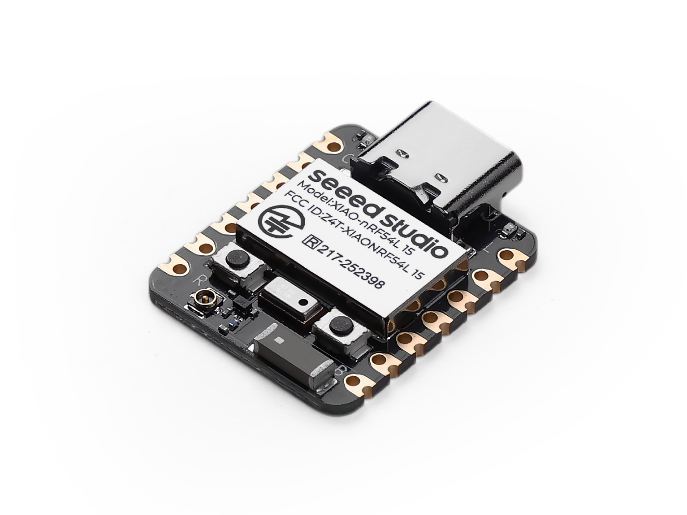
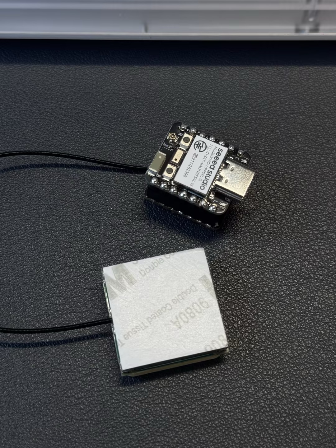
| Seeed Studio XIAO nRF54L15 Sense | L76K GNSS Module for Seeed Studio XIAO |
|---|---|
| 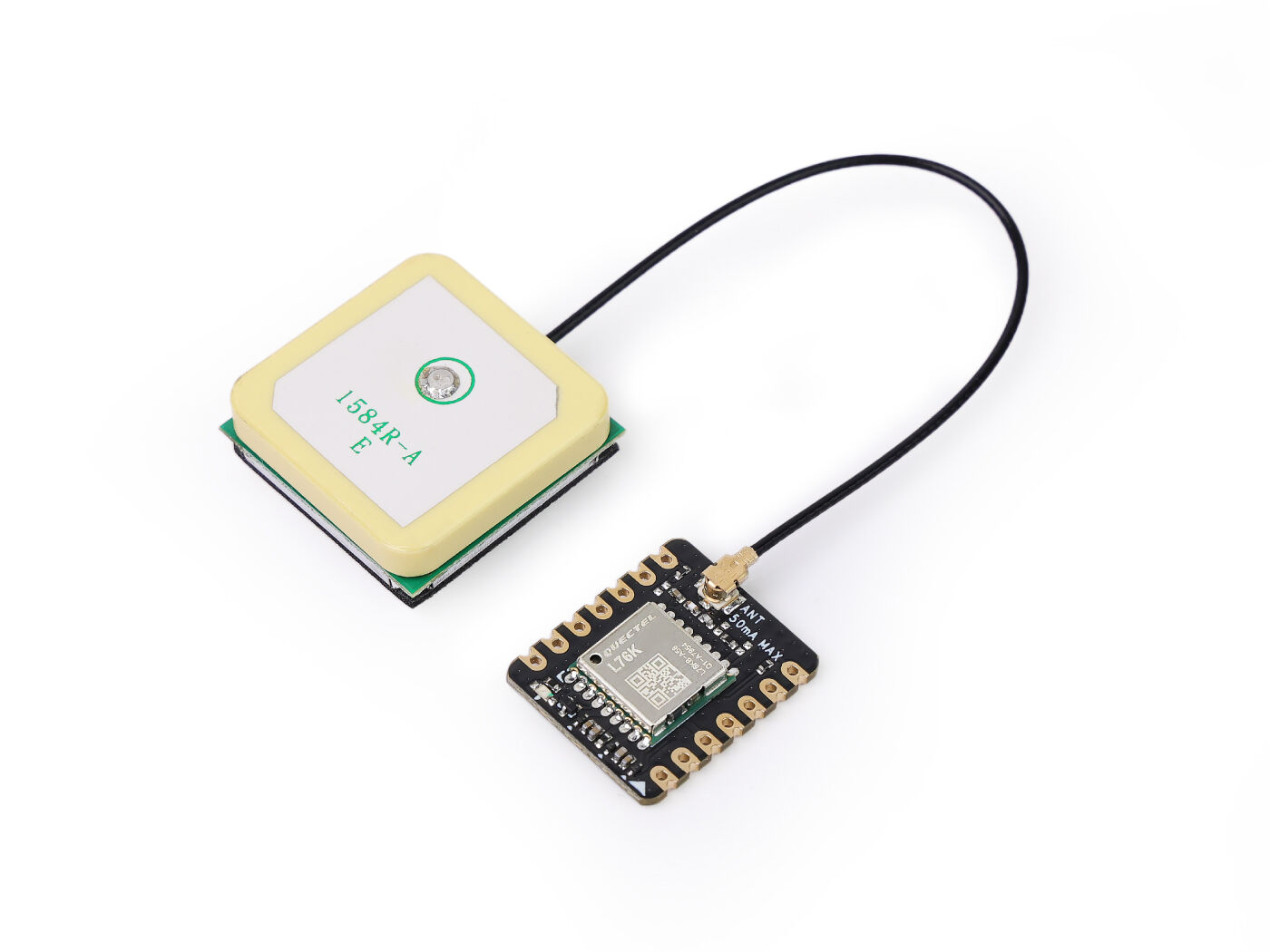 |
Software Implementation
Software
#include <zephyr/kernel.h>
#include <zephyr/device.h>
#include <zephyr/drivers/uart.h>
#include <zephyr/logging/log.h>
#include <nrfx_power.h>
#include <string.h>
#include <math.h>
#include <stdio.h>
#include <stdlib.h>

// Register log module
LOG_MODULE_REGISTER(gps_app, LOG_LEVEL_INF);

// Type definitions
#define UBYTE uint8_t
#define UWORD uint16_t
#define UDOUBLE uint32_t

// Buffer sizes
#define SENTENCE_SIZE 100
#define BUFFSIZE 800

// NMEA Commands
#define HOT_START "$PMTK101"
#define WARM_START "$PMTK102"
#define COLD_START "$PMTK103"
#define FULL_COLD_START "$PMTK104"
#define SET_PERPETUAL_STANDBY_MODE "$PMTK161"
#define SET_PERIODIC_MODE "$PMTK225"
#define SET_NORMAL_MODE "$PMTK225,0"
#define SET_PERIODIC_BACKUP_MODE "$PMTK225,1,1000,2000"
#define SET_PERIODIC_STANDBY_MODE "$PMTK225,2,1000,2000"
#define SET_PERPETUAL_BACKUP_MODE "$PMTK225,4"
#define SET_ALWAYSLOCATE_STANDBY_MODE "$PMTK225,8"
#define SET_ALWAYSLOCATE_BACKUP_MODE "$PMTK225,9"
#define SET_POS_FIX "$PMTK220"
#define SET_POS_FIX_100MS "$PMTK220,100"
#define SET_POS_FIX_200MS "$PMTK220,200"
#define SET_POS_FIX_400MS "$PMTK220,400"
#define SET_POS_FIX_800MS "$PMTK220,800"
#define SET_POS_FIX_1S "$PMTK220,1000"
#define SET_POS_FIX_2S "$PMTK220,2000"
#define SET_POS_FIX_4S "$PMTK220,4000"
#define SET_POS_FIX_8S "$PMTK220,8000"
#define SET_POS_FIX_10S "$PMTK220,10000"
#define SET_SYNC_PPS_NMEA_OFF "$PMTK255,0"
#define SET_SYNC_PPS_NMEA_ON "$PMTK255,1"
#define SET_NMEA_BAUDRATE "$PMTK251"
#define SET_NMEA_BAUDRATE_115200 "$PMTK251,115200"
#define SET_NMEA_BAUDRATE_57600 "$PMTK251,57600"
#define SET_NMEA_BAUDRATE_38400 "$PMTK251,38400"
#define SET_NMEA_BAUDRATE_19200 "$PMTK251,19200"
#define SET_NMEA_BAUDRATE_14400 "$PMTK251,14400"
#define SET_NMEA_BAUDRATE_9600 "$PMTK251,9600"
#define SET_NMEA_BAUDRATE_4800 "$PMTK251,4800"
#define SET_REDUCTION "$PMTK314,-1"
#define SET_NMEA_OUTPUT "$PMTK314,0,1,1,1,1,0,0,0,0,0,0,0,0,0,0,0,0,0,0"

// Struct definitions
typedef struct
{
 double Lon;    // GPS Longitude
 double Lat;    // GPS Latitude
 char Lon_area; // E or W
 char Lat_area; // N or S
 UBYTE Time_H;  // Time Hour
 UBYTE Time_M;  // Time Minute
 UBYTE Time_S;  // Time Second
 UBYTE Status;  // 1: Successful positioning, 0: Positioning failed
} GNRMC;

typedef struct
{
 double Lon;
 double Lat;
} Coordinates;

// Global variables and constants
char const Temp[16] = {'0', '1', '2', '3', '4', '5', '6', '7', '8', '9', 'A', 'B', 'C', 'D', 'E', 'F'};
static const double pi = 3.14159265358979324;
static const double a = 6378245.0;
static const double ee = 0.00669342162296594323;
static const double x_pi = 3.14159265358979324 * 3000.0 / 180.0;

static char buff_t[BUFFSIZE] = {0};
static GNRMC GPS;

// UART device and buffers
static const struct device *uart_dev;
static char latest_gnrmc[SENTENCE_SIZE];
static volatile bool new_gnrmc_available = false;

// Function prototypes
void DEV_Uart_SendByte(char data);
void DEV_Uart_SendString(char *data);
void L76X_Send_Command(char *data);
GNRMC L76X_Gat_GNRMC(void);
Coordinates L76X_Baidu_Coordinates(void);
Coordinates L76X_Google_Coordinates(void);
static double transformLat(double x, double y);
static double transformLon(double x, double y);
static Coordinates bd_encrypt(Coordinates gg);
static Coordinates transform(Coordinates gps);

// UART interrupt callback
static void uart_callback(const struct device *dev, void *user_data)
{
 ARG_UNUSED(user_data);
 static char temp_buffer[SENTENCE_SIZE];
 static int temp_index = 0;

 while (uart_irq_update(dev) && uart_irq_is_pending(dev))
 {
  if (uart_irq_rx_ready(dev))
  {
   uint8_t byte;
   if (uart_fifo_read(dev, &byte, 1) == 1)
   {
    if (byte == '\n')
    {
     temp_buffer[temp_index] = '\0';
     if (strncmp(temp_buffer, "$GNRMC", 6) == 0 || strncmp(temp_buffer, "$PNRMC", 6) == 0)
     {
      strncpy(latest_gnrmc, temp_buffer, SENTENCE_SIZE);
      new_gnrmc_available = true;
     }
     temp_index = 0;
    }
    else
    {
     if (temp_index < SENTENCE_SIZE - 1)
     {
      temp_buffer[temp_index++] = byte;
     }
     else
     {
      temp_index = 0; // Reset on overflow
     }
    }
   }
  }
 }
}

// Main function
int main(void)
{
 // Request constant latency mode for power management
 nrfx_power_constlat_mode_request();
 LOG_INF("Starting L76X GPS Module Example");

 // Initialize UART device
 uart_dev = DEVICE_DT_GET(DT_NODELABEL(xiao_serial));
 if (!device_is_ready(uart_dev))
 {
  LOG_ERR("UART device not ready!");
  return -1;
 }
 LOG_INF("UART device initialized.");

 // Configure UART interrupt
 if (uart_irq_callback_user_data_set(uart_dev, uart_callback, NULL) != 0)
 {
  LOG_ERR("Failed to set UART callback!");
  return -1;
 }
 uart_irq_rx_enable(uart_dev);
 LOG_INF("UART interrupt enabled.");

 // Initialize GPS module
 L76X_Send_Command(SET_NMEA_OUTPUT);
 k_msleep(100);
 L76X_Send_Command(SET_POS_FIX_1S);
 k_msleep(100);

 LOG_INF("GPS module initialized. Waiting for data...");

 while (true)
 {
  // Check for new GNRMC sentence
  if (new_gnrmc_available)
  {
   strncpy(buff_t, latest_gnrmc, BUFFSIZE);
   new_gnrmc_available = false;

   // Log raw GNRMC sentence for debugging
   LOG_INF("Raw GNRMC: %s", buff_t);

   // Parse GNRMC data
   GPS = L76X_Gat_GNRMC();

   // Output GPS data
   LOG_INF("\n--- GPS Data ---");
   LOG_INF("Time (GMT+8): %02d:%02d:%02d", GPS.Time_H, GPS.Time_M, GPS.Time_S);
   if (GPS.Status == 1)
   {
    LOG_INF("Latitude (WGS-84): %.6f %c", GPS.Lat, GPS.Lat_area);
    LOG_INF("Longitude (WGS-84): %.6f %c", GPS.Lon, GPS.Lon_area);

    // Coordinate conversion
    Coordinates baidu_coords = L76X_Baidu_Coordinates();
    LOG_INF("Baidu Latitude: %.6f", baidu_coords.Lat);
    LOG_INF("Baidu Longitude: %.6f", baidu_coords.Lon);

    Coordinates google_coords = L76X_Google_Coordinates();
    LOG_INF("Google Latitude: %.6f", google_coords.Lat);
    LOG_INF("Google Longitude: %.6f", google_coords.Lon);
    LOG_INF("GPS positioning successful.");
   }
   else
   {
    LOG_INF("GPS positioning failed or no valid data.");
   }
  }
  else
  {
   LOG_INF("No new GNRMC data available.");
  }

  k_msleep(2000); // Wait 2 seconds before next reading
 }

 return 0;
}

// Send a single byte
void DEV_Uart_SendByte(char data)
{
 uart_poll_out(uart_dev, data);
}

// Send a string
void DEV_Uart_SendString(char *data)
{
 while (*data)
 {
  DEV_Uart_SendByte(*data++);
 }
}

// Send L76X command with checksum
void L76X_Send_Command(char *data)
{
 char Check = data[1], Check_char[3] = {0};
 UBYTE i = 0;
 DEV_Uart_SendByte('\r');
 DEV_Uart_SendByte('\n');

 for (i = 2; data[i] != '\0'; i++)
 {
  Check ^= data[i]; // Calculate checksum
 }
 Check_char[0] = Temp[Check / 16 % 16];
 Check_char[1] = Temp[Check % 16];
 Check_char[2] = '\0';

 DEV_Uart_SendString(data);
 DEV_Uart_SendByte('*');
 DEV_Uart_SendString(Check_char);
 DEV_Uart_SendByte('\r');
 DEV_Uart_SendByte('\n');
}

// Parse GNRMC data
GNRMC L76X_Gat_GNRMC(void)
{
 GNRMC gps = {0}; // Initialize with zeros
 UWORD add = 0, x = 0, z = 0, i = 0;
 UDOUBLE Time = 0;

 add = 0;
 while (add < BUFFSIZE)
 {
  // Look for GNRMC or PNRMC sentence
  if (buff_t[add] == '$' && buff_t[add + 1] == 'G' && (buff_t[add + 2] == 'N' || buff_t[add + 2] == 'P') &&
   buff_t[add + 3] == 'R' && buff_t[add + 4] == 'M' && buff_t[add + 5] == 'C')
  {
   x = 0;
   for (z = 0; x < 12; z++)
   {
    if (buff_t[add + z] == '\0')
    {
     break;
    }
    if (buff_t[add + z] == ',')
    {
     x++;
     if (x == 1)
     { // Time field
      if (buff_t[add + z + 1] != ',')
      { // Check if time field is not empty
       Time = 0;
       for (i = 0; buff_t[add + z + i + 1] != '.'; i++)
       {
        if (buff_t[add + z + i + 1] == '\0' || buff_t[add + z + i + 1] == ',')
        {
         break;
        }
        Time = (buff_t[add + z + i + 1] - '0') + Time * 10;
       }
       gps.Time_H = Time / 10000 + 8; // Adjust for GMT+8
       gps.Time_M = (Time / 100) % 100;
       gps.Time_S = Time % 100;
       if (gps.Time_H >= 24)
       {
        gps.Time_H = gps.Time_H - 24;
       }
      }
     }
     else if (x == 2)
     { // Status field
      if (buff_t[add + z + 1] == 'A')
      {
       gps.Status = 1; // Position successful
      }
      else
      {
       gps.Status = 0; // Positioning failed
       break;   // Exit early if invalid
      }
     }
     else if (x == 3)
     { // Latitude field
      if (buff_t[add + z + 1] != ',')
      { // Check if latitude field is not empty
       double latitude_val = 0;
       UBYTE decimal_found = 0;
       double decimal_multiplier = 0.1;

       int k = 1;
       while (buff_t[add + z + k] != ',' && buff_t[add + z + k] != '\0')
       {
        if (buff_t[add + z + k] == '.')
        {
         decimal_found = 1;
         k++;
         continue;
        }
        if (!decimal_found)
        {
         latitude_val = latitude_val * 10 + (buff_t[add + z + k] - '0');
        }
        else
        {
         latitude_val = latitude_val + (buff_t[add + z + k] - '0') * decimal_multiplier;
         decimal_multiplier *= 0.1;
        }
        k++;
       }
       gps.Lat = latitude_val;
       gps.Lat_area = buff_t[add + z + k + 1]; // N or S
       z += k + 1;
      }
      else
      {
       gps.Status = 0; // Invalid data
       break;
      }
     }
     else if (x == 5)
     { // Longitude field
      if (buff_t[add + z + 1] != ',')
      { // Check if longitude field is not empty
       double longitude_val = 0;
       UBYTE decimal_found = 0;
       double decimal_multiplier = 0.1;

       int k = 1;
       while (buff_t[add + z + k] != ',' && buff_t[add + z + k] != '\0')
       {
        if (buff_t[add + z + k] == '.')
        {
         decimal_found = 1;
         k++;
         continue;
        }
        if (!decimal_found)
        {
         longitude_val = longitude_val * 10 + (buff_t[add + z + k] - '0');
        }
        else
        {
         longitude_val = longitude_val + (buff_t[add + z + k] - '0') * decimal_multiplier;
         decimal_multiplier *= 0.1;
        }
        k++;
       }
       gps.Lon = longitude_val;
       gps.Lon_area = buff_t[add + z + k + 1]; // E or W
       z += k + 1;
       break;
      }
      else
      {
       gps.Status = 0; // Invalid data
       break;
      }
     }
    }
   }
   break;
  }
  add++;
 }
 return gps;
}

// Convert to Baidu coordinates (BD-09)
Coordinates L76X_Baidu_Coordinates(void)
{
 Coordinates wgs84_coords;
 wgs84_coords.Lat = GPS.Lat;
 wgs84_coords.Lon = GPS.Lon;

 Coordinates gcj02_coords = transform(wgs84_coords);
 Coordinates bd09_coords = bd_encrypt(gcj02_coords);
 return bd09_coords;
}

// Convert to Google coordinates (GCJ-02)
Coordinates L76X_Google_Coordinates(void)
{
 Coordinates wgs84_coords;
 wgs84_coords.Lat = GPS.Lat;
 wgs84_coords.Lon = GPS.Lon;

 Coordinates gcj02_coords = transform(wgs84_coords);
 return gcj02_coords;
}

// Coordinate transformation helper functions
static double transformLat(double x, double y)
{
 double ret = -100.0 + 2.0 * x + 3.0 * y + 0.2 * y * y + 0.1 * x * y + 0.2 * sqrt(fabs(x));
 ret += (20.0 * sin(6.0 * x * pi) + 20.0 * sin(2.0 * x * pi)) * 2.0 / 3.0;
 ret += (20.0 * sin(y * pi) + 40.0 * sin(y / 3.0 * pi)) * 2.0 / 3.0;
 ret += (160.0 * sin(y / 12.0 * pi) + 320 * sin(y * pi / 30.0)) * 2.0 / 3.0;
 return ret;
}

static double transformLon(double x, double y)
{
 double ret = 300.0 + x + 2.0 * y + 0.1 * x * x + 0.1 * x * y + 0.1 * sqrt(fabs(x));
 ret += (20.0 * sin(6.0 * x * pi) + 20.0 * sin(2.0 * x * pi)) * 2.0 / 3.0;
 ret += (20.0 * sin(x * pi) + 40.0 * sin(x / 3.0 * pi)) * 2.0 / 3.0;
 ret += (150.0 * sin(x / 12.0 * pi) + 300.0 * sin(x / 30.0 * pi)) * 2.0 / 3.0;
 return ret;
}

static Coordinates bd_encrypt(Coordinates gg)
{
 Coordinates bd;
 double x = gg.Lon, y = gg.Lat;
 double z = sqrt(x * x + y * y) + 0.00002 * sin(y * x_pi);
 double theta = atan2(y, x) + 0.000003 * cos(x * x_pi);
 bd.Lon = z * cos(theta) + 0.0065;
 bd.Lat = z * sin(theta) + 0.006;
 return bd;
}

static Coordinates transform(Coordinates gps)
{
 Coordinates gg;
 double dLat = transformLat(gps.Lon - 105.0, gps.Lat - 35.0);
 double dLon = transformLon(gps.Lon - 105.0, gps.Lat - 35.0);
 double radLat = gps.Lat / 180.0 * pi;
 double magic = sin(radLat);
 magic = 1 - ee * magic * magic;
 double sqrtMagic = sqrt(magic);
 dLat = (dLat * 180.0) / ((a * (1 - ee)) / (magic * sqrtMagic) * pi);
 dLon = (dLon * 180.0) / (a / sqrtMagic * cos(radLat) * pi);
 gg.Lat = gps.Lat + dLat;
 gg.Lon = gps.Lon + dLon;
 return gg;
}
GPS Module Configuration and Initialization
gps_appLog Module:
-LOG_MODULE_REGISTER(gps_app, LOG_LEVEL_INF): This registers a log module named gps_app and sets its log level to INFO. This allows the program to output information through Zephyr's logging system, which is useful for debugging and monitoring.
- Type Definitions and Macros:
-UBYTE, UWORD, UDOUBLE:These are custom unsigned integer type aliases that improve code readability by clarifying the expected size of the variables.
-
SENTENCE_SIZE, BUFFSIZE:These define fixed sizes for buffers used to store NMEA sentences and larger data buffers. -
Macros like
HOT_START, SET_NMEA_OUTPUT:These macros define various NMEA protocol commands sent to the L76X GPS module to configure its operating mode, output frequency, baud rate, and so on. -
Struct Definitions:
-
GNRMC:This struct is used to store key information parsed from a GNRMC (GPS Recommended Minimum Specific data) NMEA sentence, including longitude, latitude, time, status, and cardinal directions. -
Coordinates:A simple struct to store the longitude and latitude of a geographic coordinate.
-
-
Global Variables and Constants:
buff_t:A global buffer of size BUFFSIZE used to store raw UART data.
-GPS:A global GNRMC struct instance used to hold the parsed GPS data.
-
uart_dev:A pointer to the UART device struct, used for UART communication. -
new_gnrmc_available:A volatile boolean flag that is set to true when a new valid GNRMC sentence is received, notifying the main loop that new data is available for processing. -
uart_callback() Function:-
This is a UART interrupt callback function that is triggered when the UART receives data.
-
The function reads the UART FIFO byte by byte and processes the data as a complete sentence when a newline character \n is encountered.
-
Main Function main()
-
System Initialization:
-
nrfx_power_constlat_mode_request():Requests a constant latency mode to ensure power management does not interfere with real-time operations. -
uart_dev = DEVICE_DT_GET:Retrieves the UART device handle and uses device_is_ready() to check if the device is ready. -
uart_irq_callback_user_data_set()anduart_irq_rx_enable():These configure and enable the UART receive interrupt, registering the uart_callback function as the interrupt handler to ensure asynchronous reception of GPS data.
-
-
GPS Module Initialization:
L76X_Send_Command(SET_NMEA_OUTPUT):A command is sent to configure the GPS module to output only specified NMEA sentences like GNRMC, reducing unnecessary data traffic.
-L76X_Send_Command(SET_POS_FIX_1S):Sets the GPS module's position update frequency to 1 second.
-
Main Loop:
-
The loop runs indefinitely, continuously checking the new_gnrmc_available flag.
-
If the flag is true, it copies the latest GPS sentence from latest_gnrmc to buff_t, and then calls L76X_Gat_GNRMC() to parse the data.
-
Based on the parsing result, it prints the time, WGS-84 longitude and latitude, and the converted Baidu and Google coordinates.
-
If GPS.Status is 0, it prints a "positioning failed" message.
-
If no new data is available, it prints "No new GNRMC data available."
-
k_msleep(2000): The program pauses for 2 seconds after each loop to control the output frequency.
-
Result graph
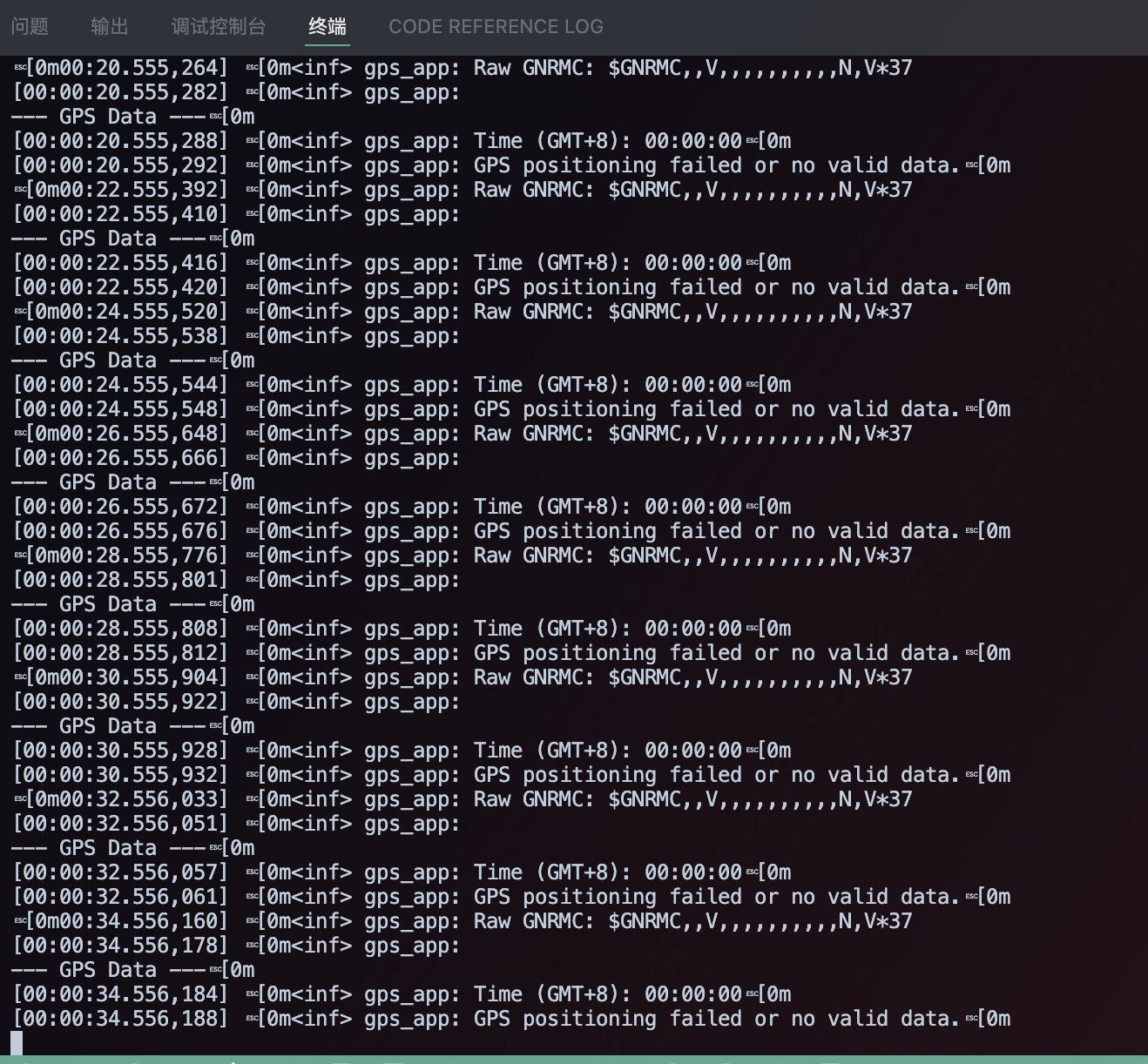 |  |
I2C
Harware Preparation
| Seeed Studio XIAO nRF54L15 Sense | Seeed Studio Expansion Board Base for XIAO |
|---|---|
| |
Software Implementation
#include <zephyr/kernel.h>
#include <zephyr/device.h>
#include <zephyr/display/cfb.h>
#include <stdio.h>
#include <string.h>
#define LOG_LEVEL CONFIG_LOG_DEFAULT_LEVEL
#include <zephyr/logging/log.h>
LOG_MODULE_REGISTER(main_app, LOG_LEVEL);
/**
* @brief Initializes the display device.
* @param[out] dev Pointer to the display device struct.
* @return 0 on success, -1 on failure.
*/
static int display_init(const struct device **dev) {
*dev = DEVICE_DT_GET(DT_CHOSEN(zephyr_display));
if (!device_is_ready(*dev)) {
LOG_ERR("Device %s not ready", (*dev)->name);
return -1;
}
if (display_set_pixel_format(*dev, PIXEL_FORMAT_MONO10) != 0) {
if (display_set_pixel_format(*dev, PIXEL_FORMAT_MONO01) != 0) {
LOG_ERR("Failed to set required pixel format");
return -1;
}
}
LOG_INF("Initialized %s", (*dev)->name);
return 0;
}
/**
* @brief Initializes the Compact Framebuffer (CFB) and display blanking.
* @param dev Pointer to the display device struct.
* @return 0 on success, -1 on failure.
*/
static int framebuffer_setup(const struct device *dev) {
if (cfb_framebuffer_init(dev)) {
LOG_ERR("Framebuffer initialization failed!");
return -1;
}
cfb_framebuffer_clear(dev, true);
display_blanking_off(dev);
return 0;
}
/**
* @brief Selects a suitable font for the display.
* @param dev Pointer to the display device struct.
* @param[out] font_width Pointer to store the width of the selected font.
* @param[out] font_height Pointer to store the height of the selected font.
* @return 0 on success, -1 if no suitable font is found.
*/
static int select_font(const struct device *dev, uint8_t *font_width, uint8_t *font_height) {
int chosen_font_idx = -1;
uint8_t current_font_width, current_font_height;
for (int idx = 0; idx < 42; idx++) {
if (cfb_get_font_size(dev, idx, ¤t_font_width, ¤t_font_height) == 0) {
if (current_font_width == 8 && current_font_height == 8) {
chosen_font_idx = idx;
*font_width = current_font_width;
*font_height = current_font_height;
cfb_framebuffer_set_font(dev, chosen_font_idx);
LOG_INF("Selected font idx: %d, width: %d, height: %d", chosen_font_idx, *font_width, *font_height);
break;
}
if (chosen_font_idx == -1 && current_font_width > 0 && current_font_height > 0) {
chosen_font_idx = idx;
*font_width = current_font_width;
*font_height = current_font_height;
cfb_framebuffer_set_font(dev, chosen_font_idx);
LOG_INF("Defaulting to font idx: %d, width: %d, height: %d", chosen_font_idx, *font_width, *font_height);
}
} else {
break;
}
}
if (chosen_font_idx == -1) {
LOG_ERR("No suitable font found or loaded!");
return -1;
}
return 0;
}
/**
* @brief Prints a single line of text at specified row and column.
* @param dev Pointer to the display device struct.
* @param text The string to print.
* @param row The row number (0-indexed) where the text should start.
* @param col The column number (0-indexed) where the text should start.
* @param font_width The width of the currently selected font in pixels.
* @param font_height The height of the currently selected font in pixels.
*/
static void print_text_by_row_col(const struct device *dev, const char *text, int row, int col,
uint8_t font_width, uint8_t font_height) {
int pixel_x = col * font_width;
int pixel_y = row * font_height;
if (cfb_print(dev, text, pixel_x, pixel_y)) {
LOG_ERR("Failed to print text: \"%s\" at row %d, col %d", text, row, col);
}
}
int main(void) {
const struct device *dev;
uint8_t font_width = 0;
uint8_t font_height = 0;
uint16_t x_res, y_res;
if (display_init(&dev) != 0) {
return 0;
}
if (framebuffer_setup(dev) != 0) {
return 0;
}
if (select_font(dev, &font_width, &font_height) != 0) {
return 0;
}
x_res = cfb_get_display_parameter(dev, CFB_DISPLAY_WIDTH);
y_res = cfb_get_display_parameter(dev, CFB_DISPLAY_HEIGHT);
LOG_INF("Display resolution: %dx%d", x_res, y_res);
cfb_set_kerning(dev, 0);
while (1) {
cfb_framebuffer_clear(dev, false);
const char *line1_text = "nRF54L15";
// Print line1 at row 1, column 2
print_text_by_row_col(dev, line1_text, 1, 2, font_width, font_height);
const char *line2_text = "Hello World";
// Print line2 at row 2, column 1
print_text_by_row_col(dev, line2_text, 2, 1, font_width, font_height);
cfb_framebuffer_finalize(dev);
k_sleep(K_MSEC(1000));
}
return 0;
}
Display Device Configuration and Initialization
-
main_appLog Module:- #define LOG_LEVEL CONFIG_LOG_DEFAULT_LEVEL and LOG_MODULE_REGISTER(main_app, LOG_LEVEL) register a log module named main_app and set its log level to the system's default configuration. This allows developers to easily debug and output information through Zephyr's logging system.
-
display_init()Function:-
*dev = DEVICE_DT_GET(DT_CHOSEN(zephyr_display));:This line retrieves the chosen display device from the Zephyr Device Tree. This approach ensures the code is hardware-agnostic. -
display_set_pixel_format(*dev, PIXEL_FORMAT_MONO10):The code attempts to set the display's pixel format to PIXEL_FORMAT_MONO10. If this fails, it then tries PIXEL_FORMAT_MONO01. This ensures the display operates in a monochrome mode, which is necessary for some display technologies (e.g., OLED or e-Paper).
-
-
framebuffer_setup()Function:-
cfb_framebuffer_init(dev):This initializes the Compact Framebuffer (CFB). CFB is a lightweight graphics library in Zephyr used for drawing text and simple graphics on displays. -
cfb_framebuffer_clear(dev, true):This clears the framebuffer and immediately writes its content to the display, ensuring a clean screen. -
display_blanking_off(dev):This turns off the display's blanking feature, which is typically a signal that the display is ready to receive data and show an image.
-
-
select_font()Function:-
cfb_get_font_size():This function loops through available fonts to find a suitable one. -
The code prioritizes a
8x8pixel font, as it is a common and easy-to-read small font. -
If an
8x8font is not found, it selects the first available non-zero-sized font as a fallback. -
cfb_framebuffer_set_font(dev, chosen_font_idx):Once a suitable font is found, it is set as the current font for the framebuffer.
-
-
print_text_by_row_col()Function:
-int pixel_x = col * font_width;and int pixel_y = row * font_height;: This function converts the text's row and column coordinates (in character units) to pixel coordinates, making text positioning more intuitive.
cfb_print():This is the core function of the CFB library used to print text at the specified pixel location.
Main Loop
The core logic of the code runs within an infinite while (1)loop:
-
Clearing the Screen:
cfb_framebuffer_clear(dev, false):At the beginning of each loop, this clears the framebuffer without immediately refreshing the display. This allows multiple elements to be drawn at once, preventing screen flickering. -
Printing Text:
-
Two strings,
line1_textandline2_text, are defined. -
print_text_by_row_col(): The custom function is used to print these two lines of text at specified row and column positions on the screen. The first line is printed at
(1, 2)and the second line at(2, 1). -
Refreshing the Display:
cfb_framebuffer_finalize(dev): This function sends all pending drawing commands from the framebuffer to the display at once, making all the content appear simultaneously. -
Delay:
k_sleep(K_MSEC(1000)):After each loop, the program pauses for 1000 milliseconds (1 second). This controls the screen update frequency, which is suitable for applications that display static information, such as a clock or sensor data, in a stable manner.
-
Result graph

SPI
Hadware Preparation
| Seeed Studio XIAO nRF54L15 Sense | ePaper Driver Board for Seeed Studio XIAO |
|---|---|
|  |
Software Implementation
#include <zephyr/kernel.h>
#include <zephyr/device.h>
#include <zephyr/drivers/display.h>
#include <lvgl.h>

#define LOG_LEVEL CONFIG_LOG_DEFAULT_LEVEL
#include <zephyr/logging/log.h>
LOG_MODULE_REGISTER(epaper_simple);

int main(void)
{
    // Get display device
    const struct device *display_dev = DEVICE_DT_GET(DT_CHOSEN(zephyr_display));
    if (!device_is_ready(display_dev)) {
        LOG_ERR("Display device not ready!");
        return 0;
    }
    LOG_INF("Display device ready.");

    // Initialize LVGL
    // Must be called before any LVGL object creation or operation
    lv_init();

    // Turn off display blanking (for ePaper, this usually triggers a full refresh to clear old content)
    if (display_blanking_off(display_dev)) {
        LOG_ERR("Failed to turn off display blanking!");
        return 0;
    }
    LOG_INF("Display blanking is off. Screen should be cleared by full refresh.");

    // Get the current active screen and set its background to white
    // This is also an LVGL-level "clear" operation to ensure the canvas is white
    lv_obj_t *scr = lv_scr_act();
    lv_obj_set_style_bg_color(scr, lv_color_white(), LV_STATE_DEFAULT);
    lv_obj_set_style_bg_opa(scr, LV_OPA_COVER, LV_STATE_DEFAULT);

    // Remove screen padding and scrollbar
    lv_obj_set_style_pad_all(scr, 0, LV_STATE_DEFAULT);
    lv_obj_set_scrollbar_mode(scr, LV_SCROLLBAR_MODE_OFF);


    // Get display width and height (for layout)
    lv_disp_t *disp = lv_disp_get_default();
    lv_coord_t width = lv_disp_get_hor_res(disp);
    lv_coord_t height = lv_disp_get_ver_res(disp);
    LOG_INF("Display width: %d, height: %d", width, height);


    // Create a centered panel
    lv_obj_t *panel = lv_obj_create(scr);
    lv_obj_set_size(panel, 300, 100);
    lv_obj_align(panel, LV_ALIGN_CENTER, 0, 0);

    // Set panel background to white, border to black for visibility
    lv_obj_set_style_bg_color(panel, lv_color_white(), LV_STATE_DEFAULT);
    lv_obj_set_style_border_color(panel, lv_color_black(), LV_STATE_DEFAULT);
    lv_obj_set_style_border_width(panel, 2, LV_STATE_DEFAULT);
    lv_obj_set_style_pad_all(panel, 10, LV_STATE_DEFAULT);


    // Add text to the panel
    lv_obj_t *label = lv_label_create(panel);
    lv_label_set_text(label, "HELLO EPAPER");

    // Set text color to black for visibility on white background
    lv_obj_set_style_text_color(label, lv_color_black(), LV_STATE_DEFAULT);
    lv_obj_set_style_text_font(label, &lv_font_montserrat_24, LV_STATE_DEFAULT);
    lv_obj_align(label, LV_ALIGN_CENTER, 0, 0);

    // Add a time label at the top right
    lv_obj_t *time_label = lv_label_create(scr);
    lv_label_set_text(time_label, "Time 07:21 PM");
    lv_obj_set_style_text_color(time_label, lv_color_black(), LV_STATE_DEFAULT);
    lv_obj_set_style_text_font(time_label, &lv_font_montserrat_18, LV_STATE_DEFAULT);
    lv_obj_align(time_label, LV_ALIGN_TOP_RIGHT, -20, 10);

    // Add a Zephyr logo at the top left
    lv_obj_t *zephyr_label = lv_label_create(scr);
    lv_label_set_text(zephyr_label, "Powered by Zephyr");
    lv_obj_set_style_text_color(zephyr_label, lv_color_black(), LV_STATE_DEFAULT);
    lv_obj_set_style_text_font(zephyr_label, &lv_font_montserrat_24, LV_STATE_DEFAULT);
    lv_obj_align(zephyr_label, LV_ALIGN_BOTTOM_LEFT, 20, -10);

    // Add author label at the bottom right
    lv_obj_t *author_label = lv_label_create(scr);
    lv_label_set_text(author_label, "Author: Stellar");
    lv_obj_set_style_text_color(author_label, lv_color_black(), LV_STATE_DEFAULT);
    lv_obj_set_style_text_font(author_label, &lv_font_montserrat_16, LV_STATE_DEFAULT);
    lv_obj_align(author_label, LV_ALIGN_BOTTOM_RIGHT, -20, -10);


    // Add four squares at the top left with a for loop
    lv_obj_t *squares[4];
    int square_offsets = 20;
    for (int i = 0; i < 4; i++) {
        squares[i] = lv_obj_create(scr);
        lv_obj_set_size(squares[i], 30, 30);
        lv_obj_set_style_bg_color(squares[i], lv_color_white(), LV_STATE_DEFAULT);
        lv_obj_set_style_border_color(squares[i], lv_color_black(), LV_STATE_DEFAULT);
        lv_obj_set_style_border_width(squares[i], 2, LV_STATE_DEFAULT);
        lv_obj_set_style_radius(squares[i], 0, LV_STATE_DEFAULT);
        lv_obj_align(squares[i], LV_ALIGN_TOP_LEFT, square_offsets, 20);
        square_offsets+=40;
    }

    while (1) {
        lv_task_handler();
        k_sleep(K_MSEC(1000)); // Lower refresh rate, suitable for ePaper
    }
    return 0;
}
Device Initialization:
-
The code first obtains the display device from the device tree using
DEVICE_DT_GET(DT_CHOSEN(zephyr_display)). -
It then calls
device_is_ready()to check if the device is properly initialized and ready for operation. This is a crucial first step for any hardware interaction.
LVGL Initialization:
lv_init()is the entry point for the LVGL graphics library. It must be called before any LVGL objects are created or any operations are performed, as it initializes the library's internal state.
Screen Clearing:
-
The
display_blanking_off()function is called. For E-Paper displays, this typically triggers a full refresh to clear any old content on the screen. -
To further ensure a clean canvas, the code uses
lv_scr_act()to get the current active screen and sets its background color to white usinglv_obj_set_style_bg_color(), covering the entire display area.
Screen Layout Preparation:
-
The functions
lv_disp_get_hor_res()andlv_disp_get_ver_res()are used to get the actual width and height of the display, which is helpful for precise UI element placement later on. -
The code also removes the screen's padding
(lv_obj_set_style_pad_all())and scrollbar(lv_obj_set_scrollbar_mode())to maximize the usable drawing area.
UI Element Creation and Configuration:
-
Panel: A panel object is created with
lv_obj_create(scr). Its size and centered alignment are set usinglv_obj_set_size()andlv_obj_align(). Its style, including the white background and black border, is configured with functions likelv_obj_set_style_bg_color()andlv_obj_set_style_border_color(). -
Labels:
-
lv_label_create()is used to create text labels. -
lv_label_set_text()sets the text content of the labels. -
lv_obj_set_style_text_color()and lv_obj_set_style_text_font() are used to set the text color and font size.
-
-
The
lv_obj_align()function places each label in a specific location on the screen, such as center, top-right, bottom-left, and bottom-right.
Squares: A for loop is used to create four small square objects. Their size, style (white fill with a black border), and position are set sequentially, arranging them horizontally in the top-left corner of the screen.
Main Loop:
-
The while(1)loop is the continuous execution part of the program. -
lv_task_handler()is called continuously within the loop to process all LVGL internal tasks, such as updating UI elements and handling events. -
k_sleep(K_MSEC(1000))pauses the thread for 1000 milliseconds. For static d
Result graph

Tech Support & Product Discussion
Thank you for choosing our products! We are here to provide you with different support to ensure that your experience with our products is as smooth as possible. We offer several communication channels to cater to different preferences and needs.