Seeed Studio XIAO nRF54L15 Sense Zigbee
This tutorial guides you through implementing Zigbee applications on the Seeed Studio XIAO nRF54L15 development board, this board combines Wi-Fi, Bluetooth Low Energy (BLE), and Zigbee connectivity, making it perfect for IoT applications. The examples in this guide use the NCS to bring Zigbee functionality to life.
If you haven't prepared your NCS, refer to the Getting Started Guide.
If you are concerned that the nRF Connect SDK has not been downloaded completely or has issues, you can verify the integrity and correctness of the downloaded nRF Connect SDK in the following way. Select Manage west workspace, then select West Update, as shown below.
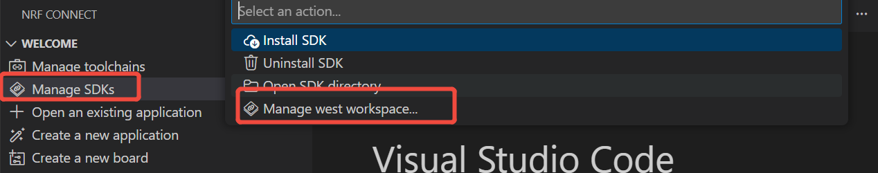
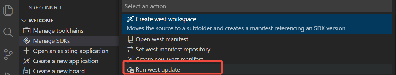
Table of Contents
Zigbee Overview
Zigbee is a low-power, low-bandwidth wireless communication protocol based on the IEEE 802.15.4 standard. It is tailored for IoT scenarios such as home automation, smart cities, and industrial control, offering robust mesh networking capabilities for reliable communication in dynamic environments.
- We will provide a brief explanation of Zigbee-related content. If you want to directly refer to the application examples, you can also skip ahead.
Zigbee Data Model
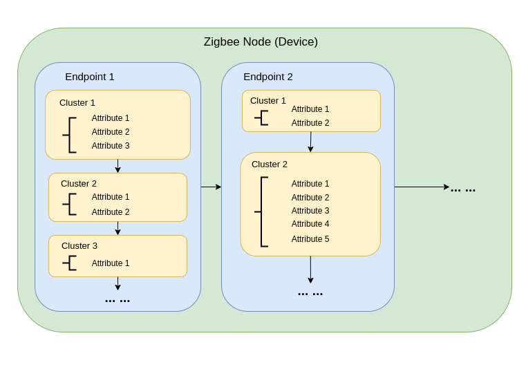
Zigbee communication relies on the Zigbee Cluster Library (ZCL), which defines how devices organize their functionality and interact. Key components include:
-
Device Types Zigbee devices (e.g., switches, sensors, lights) are pre-defined with specific behaviors, grouped into functional Clusters.
-
Clusters Clusters are logical groupings of:
- Attributes: Represent device states, like brightness or temperature.
- Commands: Trigger actions, such as turning a light on or setting brightness to 50%.
Examples:
- On/Off Cluster: Controls binary states like power.
- Level Control Cluster: Adjusts intensity or brightness.
- Temperature Measurement Cluster: Sends temperature readings.
- Scenes Cluster: Saves and recalls preset configurations.
-
Attributes & Commands Attributes store device data (e.g., state, configuration), while commands initiate actions.
Zigbee Network Architecture
A Zigbee network consists of three primary node types:
-
Zigbee Coordinator (ZC)
- Serves as the central hub of the network.
- Handles network creation, device authentication, and address allocation.
- Responsible for initializing and managing the network.
- Each Zigbee network can have only one Coordinator.
-
Zigbee Router (ZR)
- Extends the network range by relaying messages between devices.
- Supports additional devices joining the network.
- Typically mains-powered to ensure constant operation and reliable message relaying.
- Battery-powered Routers are possible but less common due to higher energy demands.
Of course, routers are not necessary. When the distance is short, routers can be omitted. For example, our next demo does not use a router.
- Zigbee End Device (ZED)
- Lightweight and power-efficient devices that communicate with a parent node (either a Coordinator or Router).
- Do not route messages to other devices.
- Optimized for battery operation and typically enter sleep modes to conserve energy.
-
Addressing and Routing:
- Zigbee uses a 16-bit addressing scheme. Devices communicate through a mix of direct and indirect addressing.
- Routing decisions are made by Routers using algorithms like AODV (Ad hoc On-demand Distance Vector).
-
Power Management:
- Zigbee End Devices are optimized for low power consumption. They often operate in sleep mode and only wake when needed.
- Routers and the Coordinator are generally mains-powered for consistent availability.
Network Topologies
Zigbee supports three primary network topologies, depending on the application requirements and environment:
1. Mesh Topology
-
A single Coordinator and multiple Routers form a self-healing, robust network.
-
Devices can dynamically reroute messages if a communication path is disrupted, ensuring high reliability.
-
Ideal for large-scale networks requiring wide coverage and redundancy.
-
Key Features:
- Dynamic rerouting ensures high reliability.
- Supports large networks with scalable coverage.
- Self-healing mechanisms increase fault tolerance.
2. Tree Topology
-
The Coordinator acts as the root of a hierarchical structure, with Routers forming branches.
-
Each branch can have multiple End Devices or additional Routers, creating a tree-like structure.
-
Communication depends on hierarchical paths, which introduces potential single points of failure.
-
Key Features:
- Works well for structured environments.
- Easier to set up and manage than a mesh network.
- Vulnerable to branch failure, which can disconnect entire sub-networks.
3. Star Topology
-
All devices communicate directly with the Coordinator.
-
Simple to deploy, but the Coordinator is a single point of failure.
-
Best suited for small networks where devices are located close to the Coordinator.
-
Key Features:
- Easy to set up and manage.
- Limited scalability due to range and device capacity constraints.
- Reliance on the Coordinator for all communication reduces fault tolerance.
Our next demo is also this type of topology
Started with NCS Zigbee
Hardware Preparation
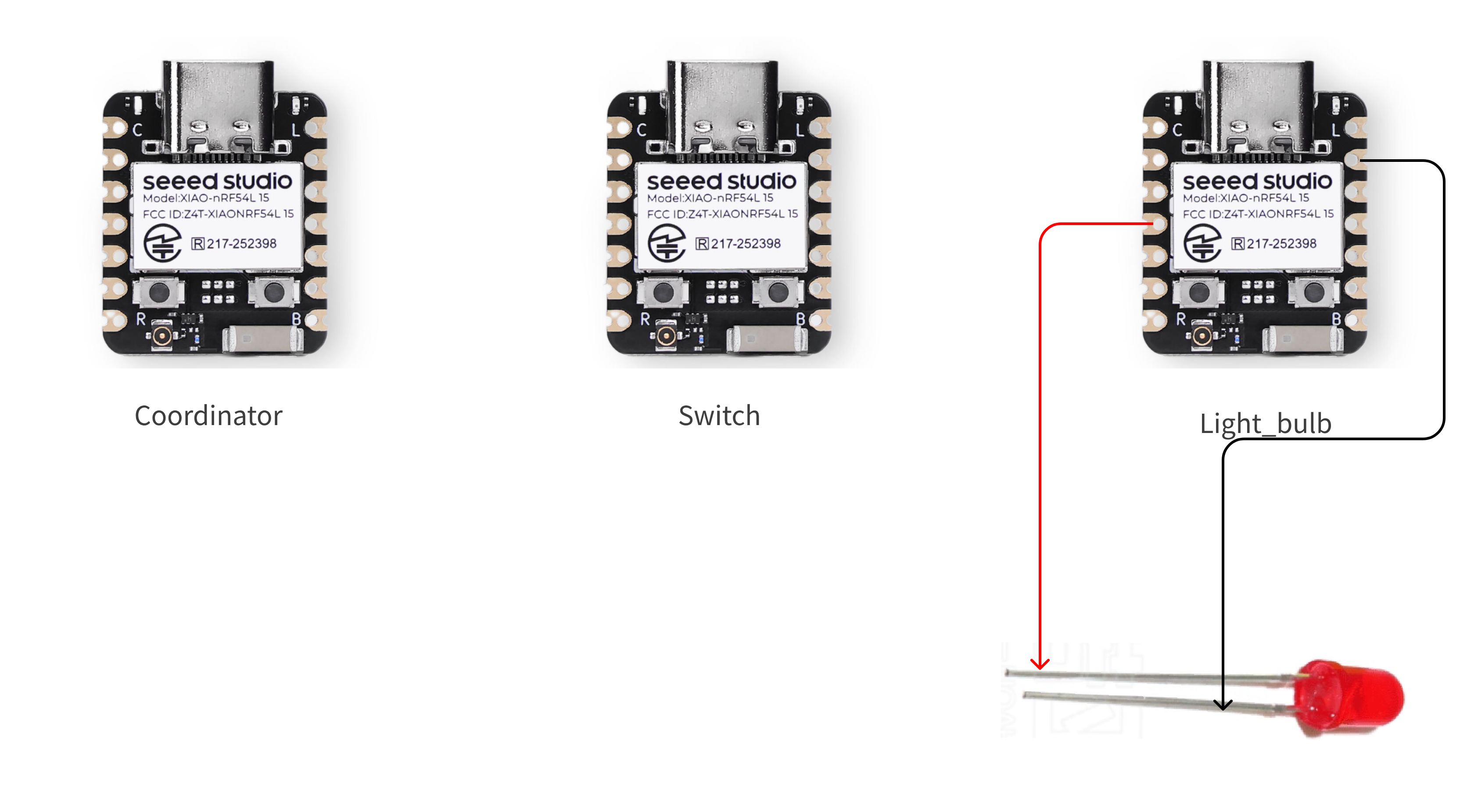
You need to prepare 3 XIAO nRF54L15 boards.
| Seeed Studio XIAO nRF54L15 Sense |
|---|
 |
connect the devices in the way shown in the figure
Software Preparation
Step 1. Install the Zigbee R23 plugin
- Click NCS plugin icon -> Create a new application and select the mode as Browse nRF Connect SDK Add-on Index.
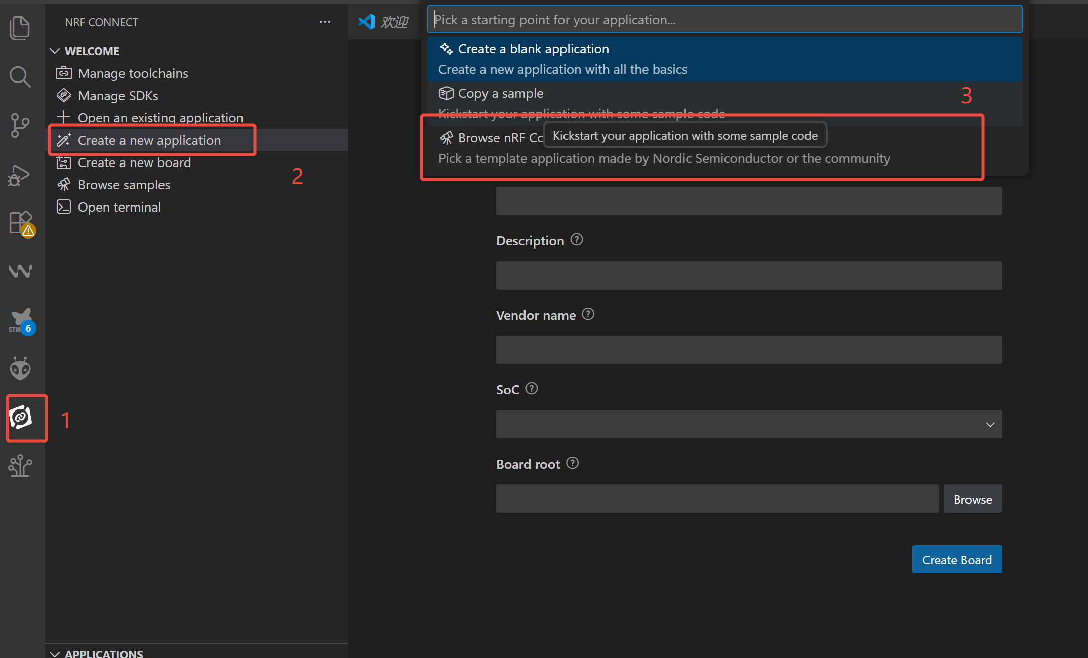
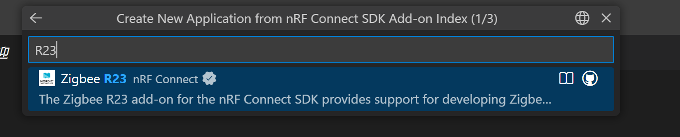
- Search forR23, go to Zigbee R23 nRF Connect -> V1.2.1
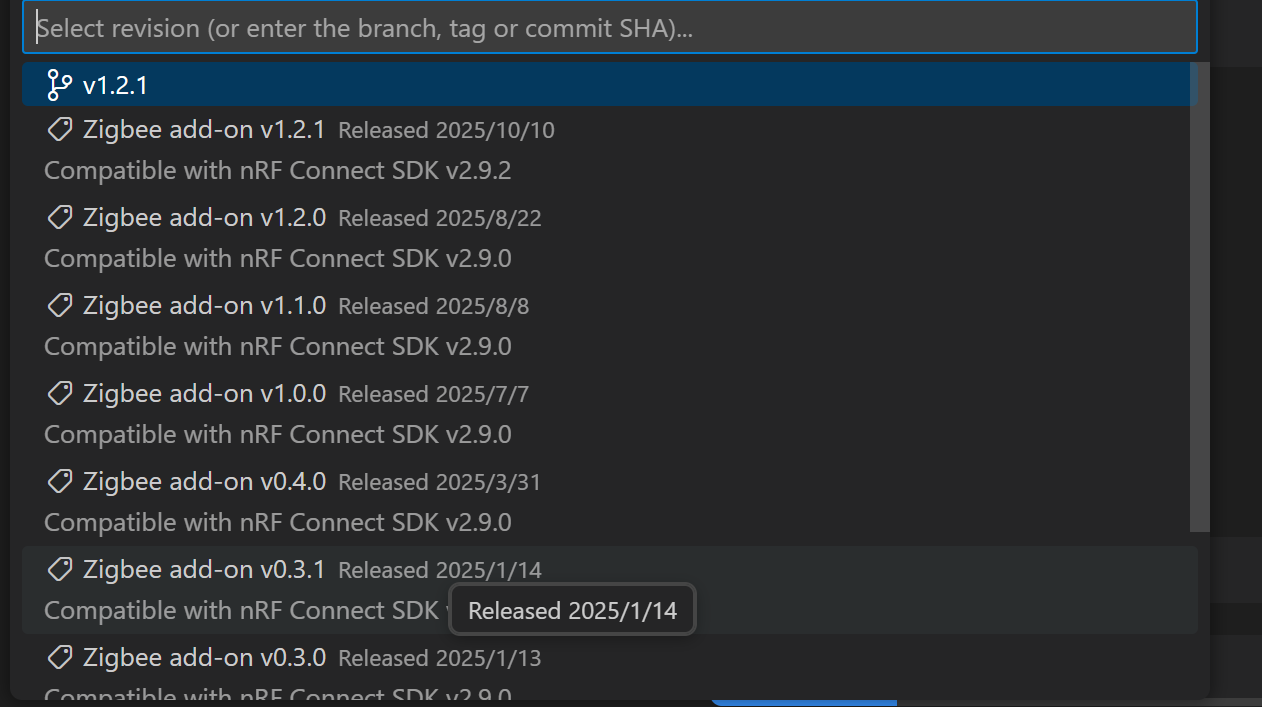
- Select the latest version -> Select the workspace directory and create it
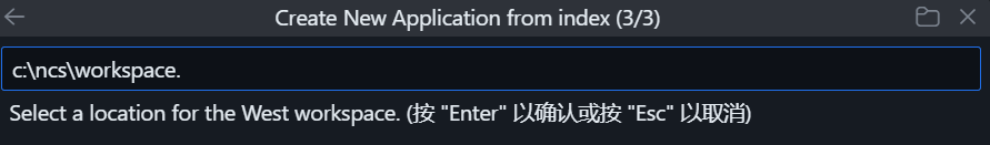
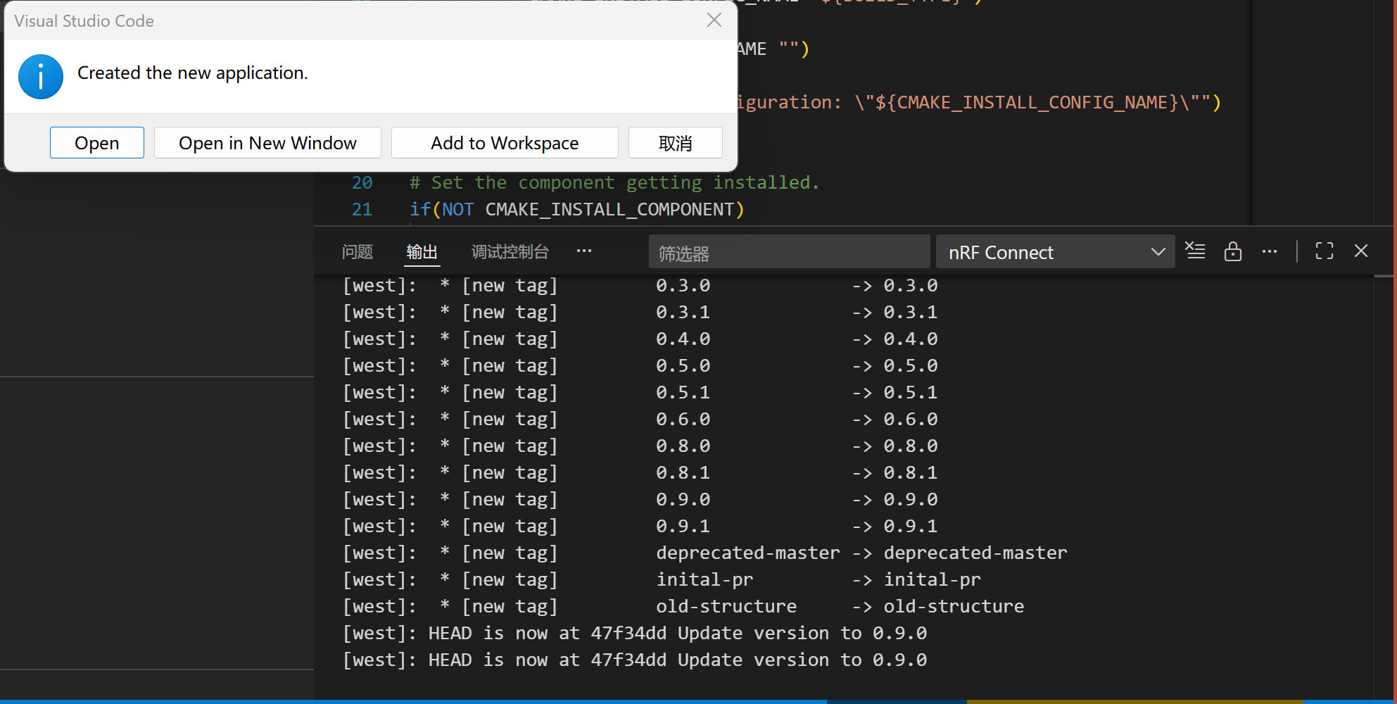
Wait for the Zigbee plugin to be installed completely, and the NCS version will be switched to v2.9.2 automatically. Since the plugin is quite large (over 4 GB), the download process will take a long time. Please keep the network connection stable and do not interrupt the process halfway.
- A pop-up prompt will appear upon completion of the creation.
Step 2. Code Preparation
- Refer to the official Seeed Studio repository to obtain examples.
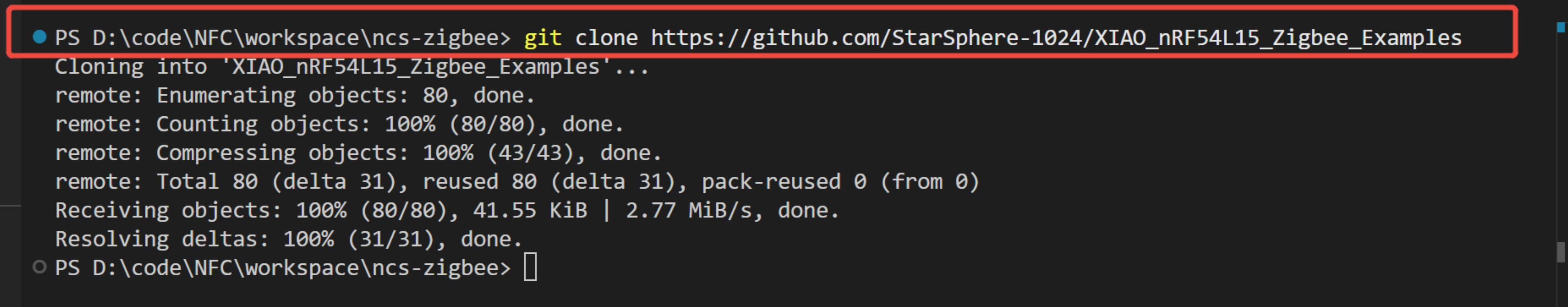
- Alternatively, if you have a Git environment set up, you can directly pull the code into the file directory you specified just now.
git clone https://github.com/StarSphere-1024/XIAO_nRF54L15_Zigbee_Examples
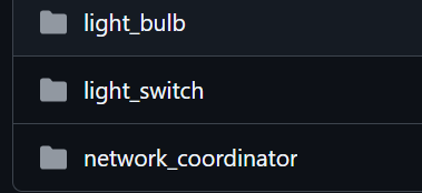
After obtaining the sample code, let's have a brief understanding of it:
1.The boards directory contains board-level configuration files, which are used to adapt to hardware differences between different development boards (such as pins and peripherals):
- The .overlay files inside are "Device Tree Overlay files", which are used to modify the default hardware configurations of the chip/development board;
- For example, xiao_nrf54l15_nrf54l15_cpuapp.overlay is a configuration specifically written for XIAO nRF54L15 (e.g., mapping the D3 pin to the LED control pin in the code);
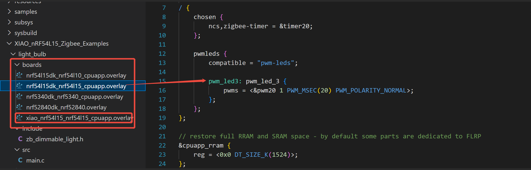
- Other files (e.g., nrf54l15dk_xxx.overlay) are intended for Nordic's official development kits (DKs), so you don't need to concern yourself with them—only focus on the files prefixed with xiao_xxx.
- The include directory is where header files are stored:
- zb_dimmable_light.h is the functional header file for Zigbee dimmable lights, which defines the Zigbee protocol-related functions and parameters for the light node (e.g., brightness control, status reporting).
- The src directory is where core code is stored:
- main.c is the entry file of the entire project, containing the program startup logic, Zigbee network initialization, and LED control logic (e.g., controlling the level of the D3 pin after receiving a switch command).
- Files in the root directory These are project build and configuration files (standard files of the NCS/Zephyr framework):
- CMakeLists.txt: A CMake build script that defines which files the project needs to compile and which libraries it depends on;
- Kconfig.sysbuild: Configures the project's compilation options (e.g., whether to enable Zigbee functionality, debug logs);
- prj.conf: The core configuration file of the project, which sets chip parameters and Zephyr system parameters (e.g., enabling GPIO functionality, Zigbee protocol stack);
- sample.yaml: An NCS sample configuration file that describes basic information about the project (e.g., supported development boards, function descriptions).
Compile and Flash the Code
This guide shows you how to add an existing application (taking light_switch as an example) to your VS Code environment, and compile and flash it to your target hardware (taking xiao_nrf54l15 as an example).
Step 1. Add the application to the workspace
-
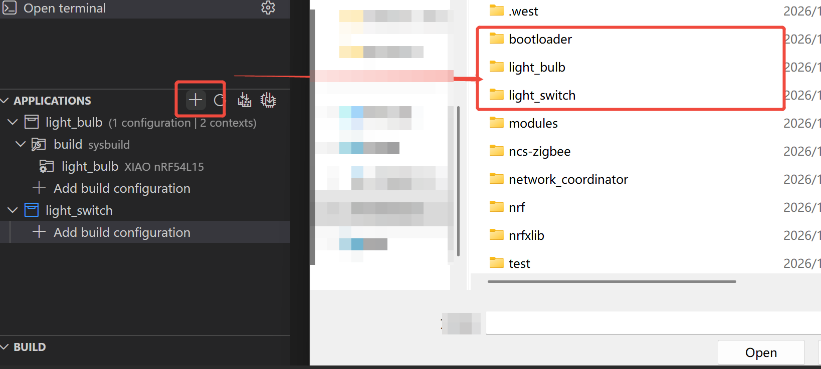
Locate the APPLICATIONS panel: In the sidebar, find the panel named "APPLICATIONS".
-
Add an existing application: Click the "+" (Add an existing application) icon in the upper right corner of the panel, as indicated by the red box in the figure below.
-
Select the application folder: In the pop-up file browser window, navigate to the folder where your project is located (e.g., D:...\workspace). From the list, select the application folder you want to flash—light_switch in this example—and then click the "Open" button.
Step 2. Create and Configure Compilation Options
-
Add a build configuration: In the "APPLICATIONS" panel, you will see the newly added light_switch project. Click on "+ Add build configuration" below it.
-
Configure compilation parameters: In the opened "Add Build Configuration" page, make the following settings: SDK and Toolchain: Your installed nRF Connect SDK and toolchain will usually be selected automatically—please verify that the version is correct. (If the plugin you downloaded earlier is intact, V2.9 will be selected here automatically.)
-
Board target: This is the most critical step. You need to select the hardware on which the code will run. Click "Browse" or search directly in the input box. As shown in the figure, the target board you need to select is xiao_nrf54l15/nrf54l15/cpuapp. You can check "Custom" to quickly filter or find boards that are not officially supported.
-
Other configurations: Unless there are special requirements, leave other settings such as Kconfig fragments and Devicetree overlays as default for now.
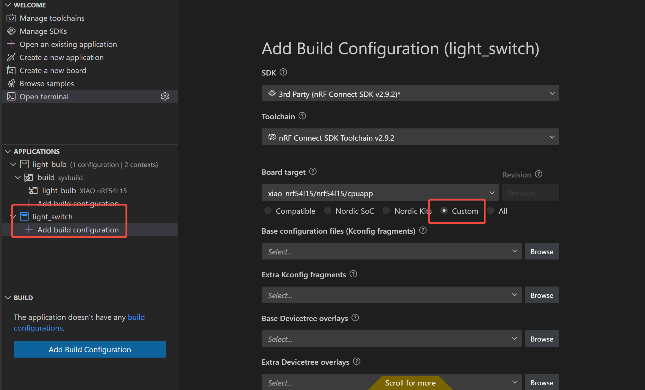
It is recommended to first check "Custom" to quickly filter or find boards that are not officially supported, and then locate the target board you need to select:xiao_nrf54l15/nrf54l15/cpuapp. If you search directly, the troubleshooting process may take too long, and the target board might not be found.
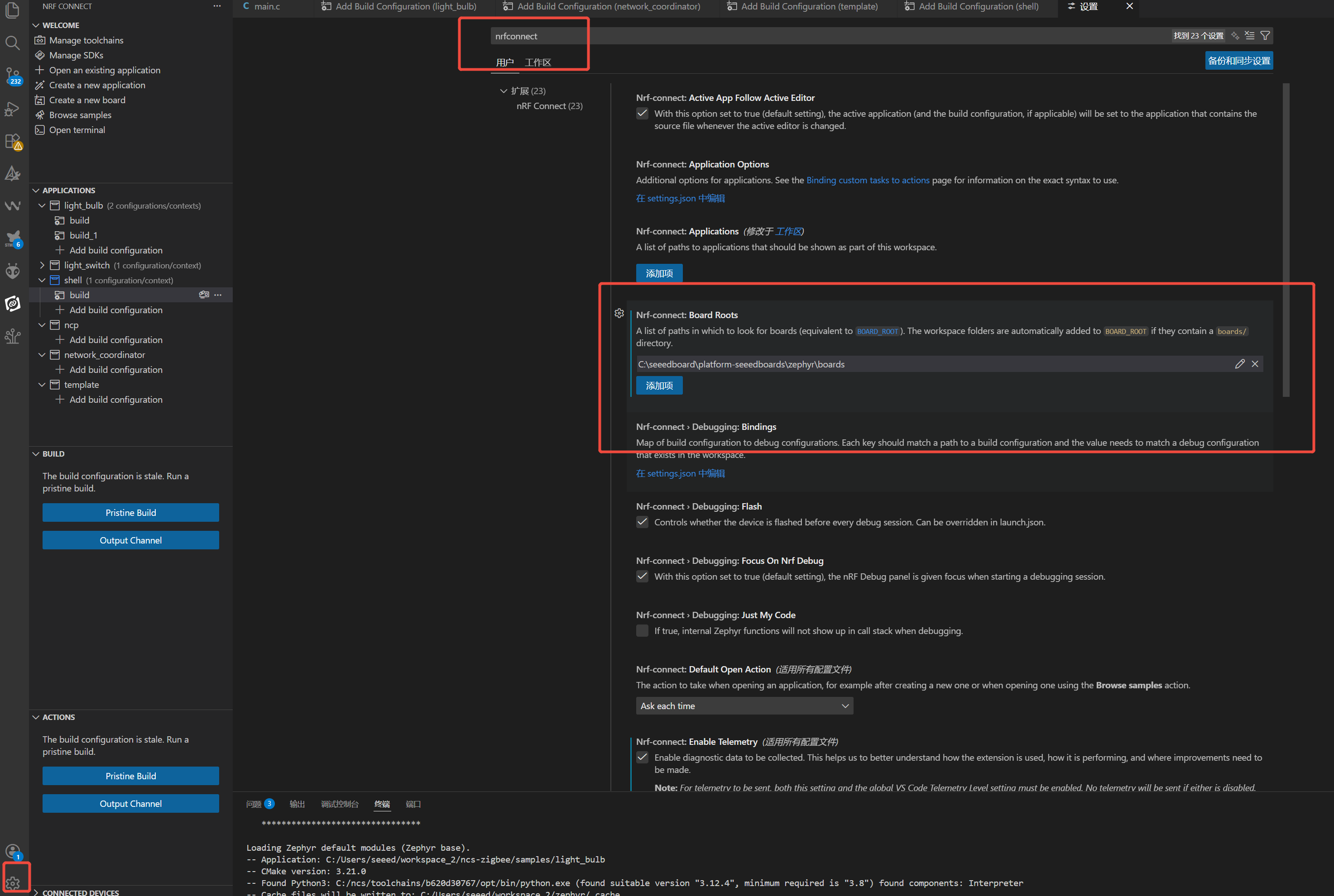
- Update the board-level files. If your files have not been updated for a long time, it is also recommended that you update them before use.
For the detailed tutorial, you can refer to the link below. Getting Started Guide.
Step 3. Compilation and Flashing
-
Connect the hardware: Ensure that your target hardware (e.g., XIAO nRF54L15 development board) is properly connected to your computer via a data cable.
-
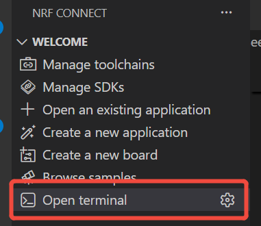
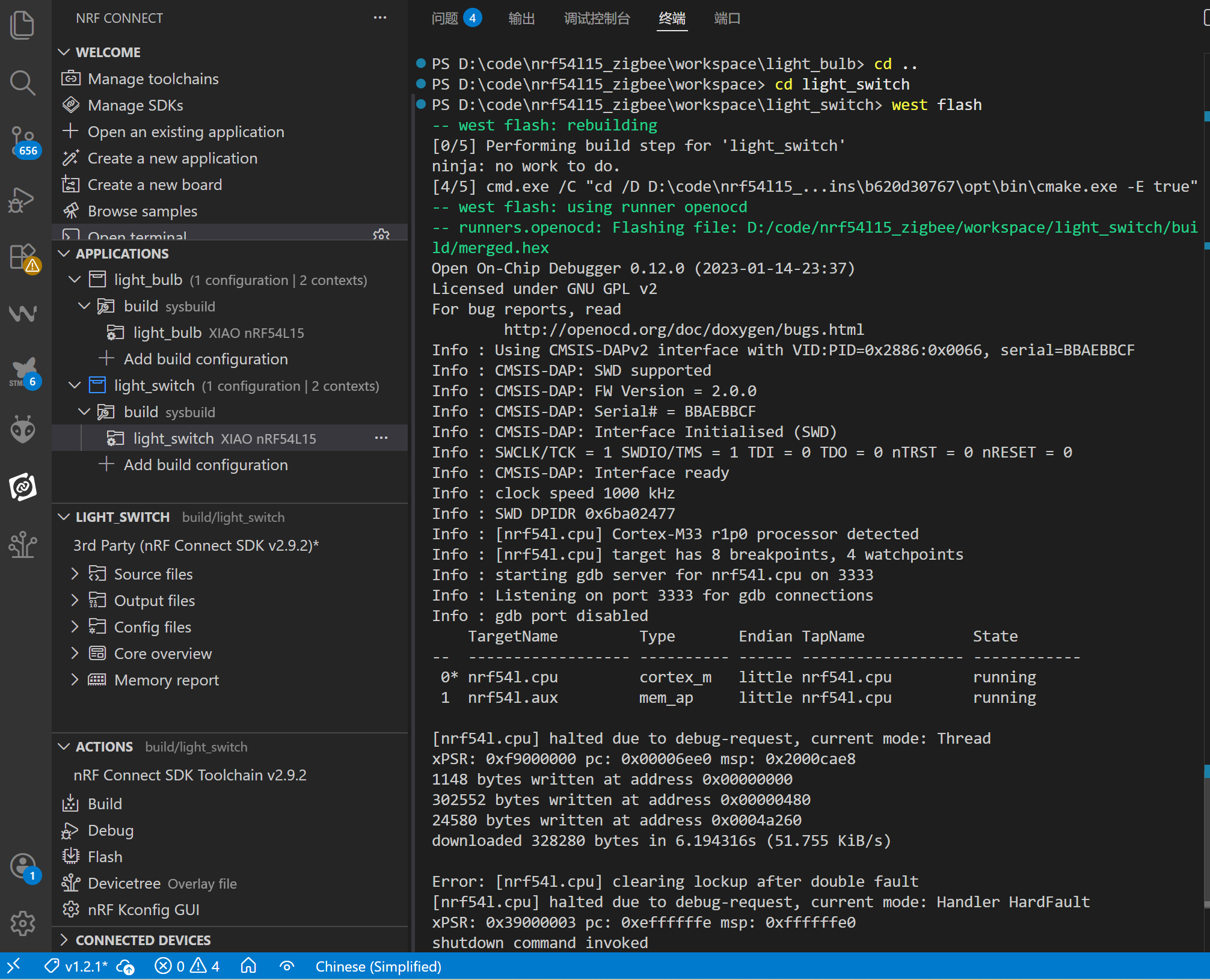
Open the terminal: In the WELCOME panel of the NRF CONNECT extension, locate and click on the "Open terminal" option (marked by the red box in the figure).
- Navigate to the project directory: In the terminal, use the cd command to enter your project folder.
cd D:\code\nrf54115_zigbee\workspace\light_switch\.lbuild
west flash
-
Please replace this path with your own actual project path.
-
Monitor the flashing process: The terminal will output detailed logs, including the compilation progress, connection to the debugger (e.g., CMSIS-DAP), flash erasure, and data writing processes.
-
Similarly, flash the remaining two code projects following the same steps.
-
If you are concerned about whether the code has been flashed successfully, there are the method to verify it:
- Connect to the development board via a serial port and observe the serial port output (this method not only verifies the flashing result but also allows you to view the program running logs intuitively, making the verification logic clearer).
Connect to Zigbee
Step 1. Connect to Zigbee
- Power on and start the XIAO development board with the Coordinator program loaded.
- Observe the logs in the serial port assistant, and wait for the coordinator to complete Zigbee stack initialization and network parameter configuration until serial port information is output.
- Keep the coordinator powered on to maintain the network continuously, which provides a foundation for subsequent devices to join the network.
Step 2. Network Joining Configuration for Light Bulb End
-
After the powered-on coordinator network is ready, power on and start the XIAO development board with the Light Bulb program loaded.
-
The light bulb end automatically starts network scanning to find available Zigbee coordinator networks.
-
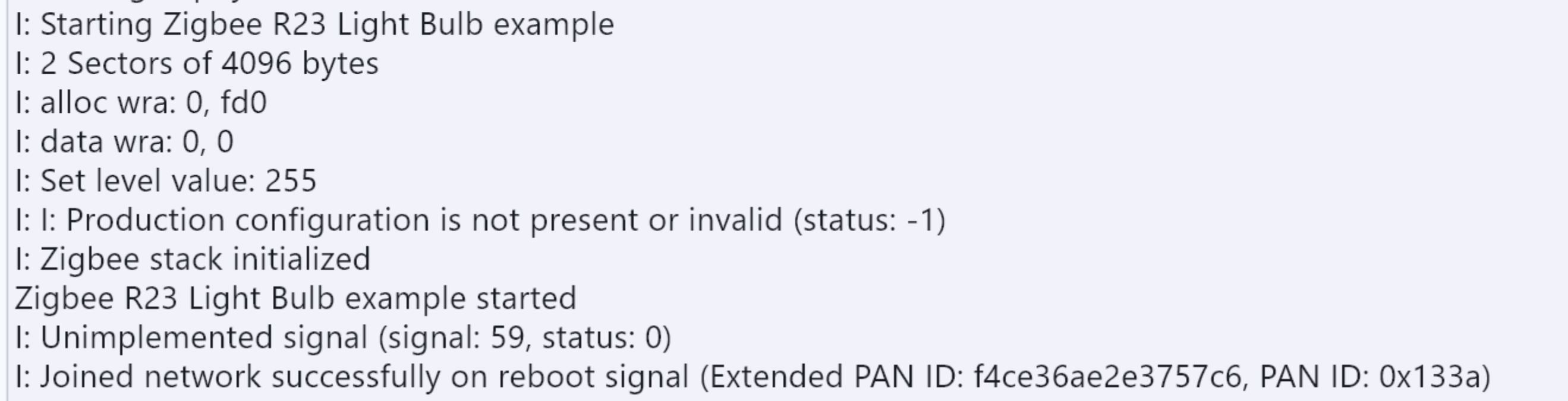
Check the serial port logs to confirm that the light bulb end has successfully joined the coordinator network. Reference for core logs:
Step 3. Network Joining and Device Discovery for Light Switch End
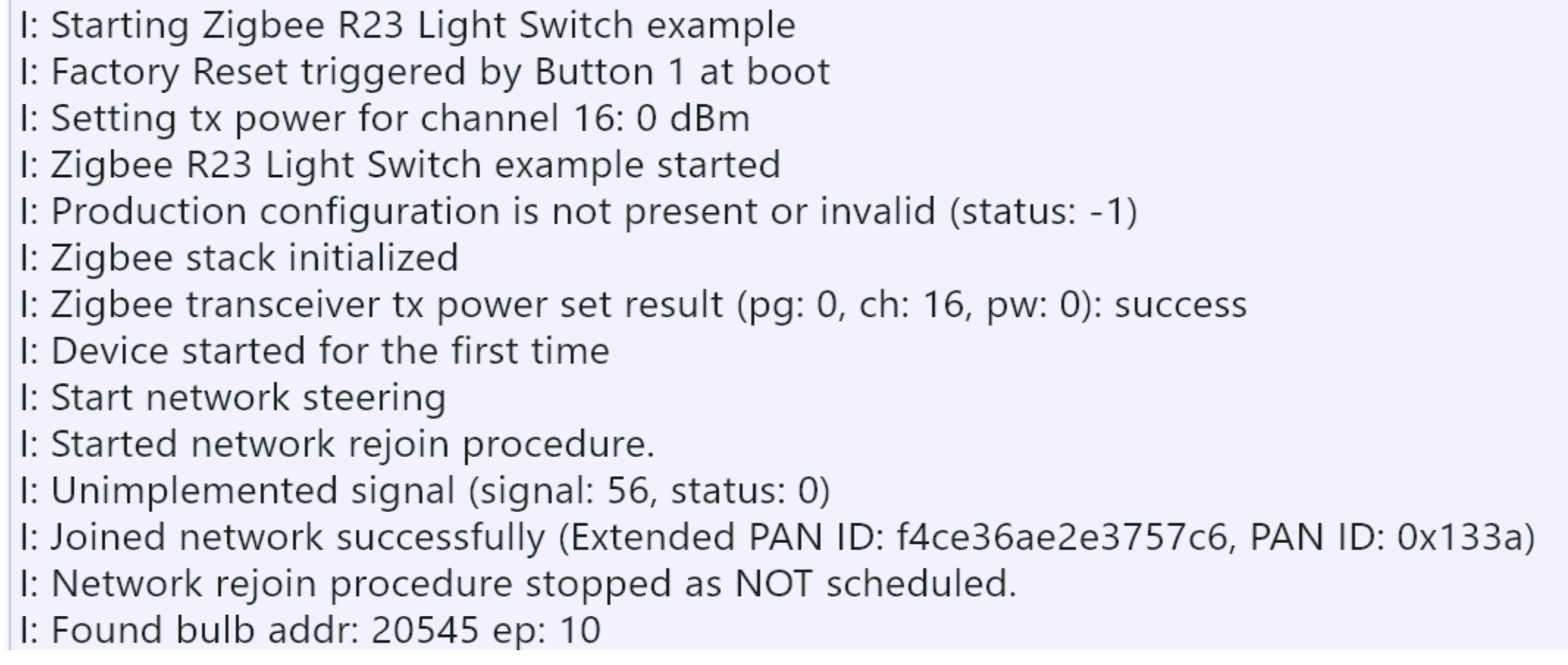
- After confirming the light bulb end has successfully joined the network, power on and start the XIAO development board with the Light Switch program loaded (trigger a factory reset via the onboard button as needed to ensure network rescanning). 2.The light switch end automatically scans and joins the same coordinator network. Reference for core logs:
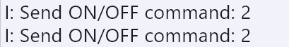
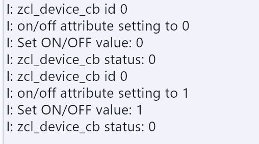
- Check the serial port logs of the light bulb end to confirm the command is received and executed, and the LED completes the on/off action. Reference for core logs:
Zigbee Network Reset Procedure
Step 1. Network Reset for Coordinator
Press the onboard button of the network coordinator to complete the Zigbee network reset.
Step 2. Reset and Rejoin of Light Control Devices (Light Switch/Light Bulb)
- Press and hold the onboard button of the light control device (light switch/light bulb);
- Press the reset button of the device;
- Release the onboard button. The device will complete the reset and automatically join the new Zigbee network.
Important: If the device is powered by a battery, the serial port must be explicitly disabled; otherwise, the program will fail to start.
Result
If everything goes well, you will see the following results.
FQA
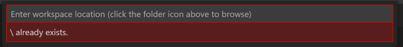
1.Do NOT use an overly long directory as the installation root directory. Otherwise, when compiling examples on Windows, you will frequently encounter compilation errors caused by excessively long directory names.
Tech Support & Product Discussion
Thank you for choosing our products! We are here to provide you with different support to ensure that your experience with our products is as smooth as possible. We offer several communication channels to cater to different preferences and needs.