Getting Started with XIAO nRF54LM20A Sense
Introduction
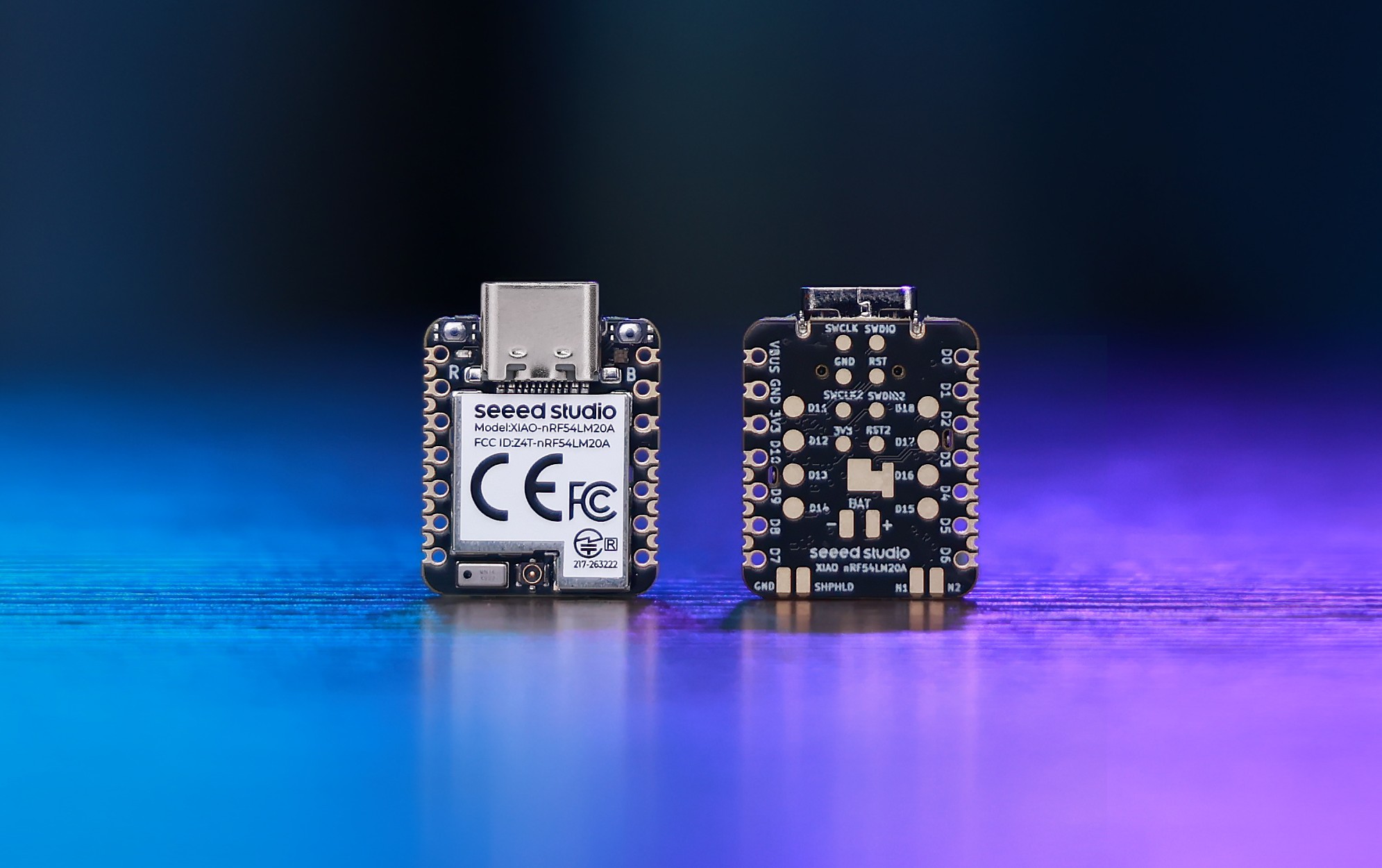
Seeed Studio XIAO nRF54LM20A Sense is a compact, ultra-low-power wireless development board built around Nordic Semiconductor’s nRF54LM20A SoC. It combines a 128 MHz Arm Cortex-M33 processor, 512 KB RAM, 2 MB on-chip NVM, multiprotocol 2.4 GHz wireless connectivity, onboard IMU, digital microphone, 8MB external flash, IPEX antenna connector, and nPM1300 PMIC for advanced battery-powered IoT, wearable, smart sensing, and edge AI applications.
Specification
| Product Name | Seeed Studio XIAO nRF54LM20A | Seeed Studio XIAO nRF54LM20A Sense |
|---|---|---|
| Processor | Arm® Cortex®-M33 128 MHz & RISC-V 128 MHz Coprocessor | |
| RAM | 512KB | |
| Flash | 2 MB Non-volatile Memory (NVM) | |
| External Flash | 8MB onboard external flash | |
| PMIC / Battery | nPM1300 PMIC for power regulation and battery charging | |
| Interface | 28x GPIO Pin | |
| Onboard | 1x User LED (R/G/B 3 Color) | 1x User LED (R/G/B 3 Color) |
| Wireless Connectivity | Bluetooth LE 6.0 (include Channel Sounding) | |
| Power Input | Type-C: 5V | |
| Low Power Mode (3.7V@2A) | / | Light-Sleep: ~9.96µA |
| Software Compatibility | Nordic nRF Connect SDK (based on Zephyr RTOS) | |
| Working Temperature | -20°C to 70°C | |
| Dimensions | 21 x 17.8mm | |
Features
-
Powerful SoC with Advanced Connectivity & Security
Seeed Studio XIAO nRF54LM20A Sense is a compact, ultra-low-power wireless development board powered by Nordic Semiconductor’s nRF54LM20A SoC. It features a 128 MHz Arm Cortex-M33 processor, 512 KB RAM, 2 MB on-chip NVM, a 128 MHz RISC-V coprocessor, multiprotocol 2.4 GHz wireless connectivity, onboard IMU, digital microphone, 8MB external flash, IPEX antenna connector, and Nordic nPM1300 PMIC for efficient power management.With support for Bluetooth LE, Bluetooth Channel Sounding, Bluetooth Mesh, Thread, Zigbee, Matter, and proprietary 2.4 GHz protocols up to 4 Mbps, this board is built for next-generation connected products. The onboard motion and audio sensors make it ideal for wearables, smart sensing, TinyML, gesture recognition, voice-triggered devices, and battery-powered IoT applications.
-
Ultra-Low Power Efficiency
Built on Nordic nRF54LM20A and nPM1300 PMIC, XIAO nRF54LM20A Sense achieves a measured deep sleep current of only 4.76 µA under BAT power. Combined with the nPM1300 PMIC and its 0.33 µA Ship Mode BAT current, in active wireless operation, it records an average current of 3.87 mA with a 3.7 V simulated battery input and TX power set to +8 dBm, the board is ideal for long-life battery-powered sensing applications, wearables, and always-on IoT devices.
-
Streamlined Development Experience
Full support for Nordic nRF Connect SDK and PlatformIO (Zephyr) enables efficient embedded development workflows. (Note: Arduino IDE is currently not supported)
Hardware Overview
- XIAO nRF54LM20A
- XIAO nRF54LM20A Sense
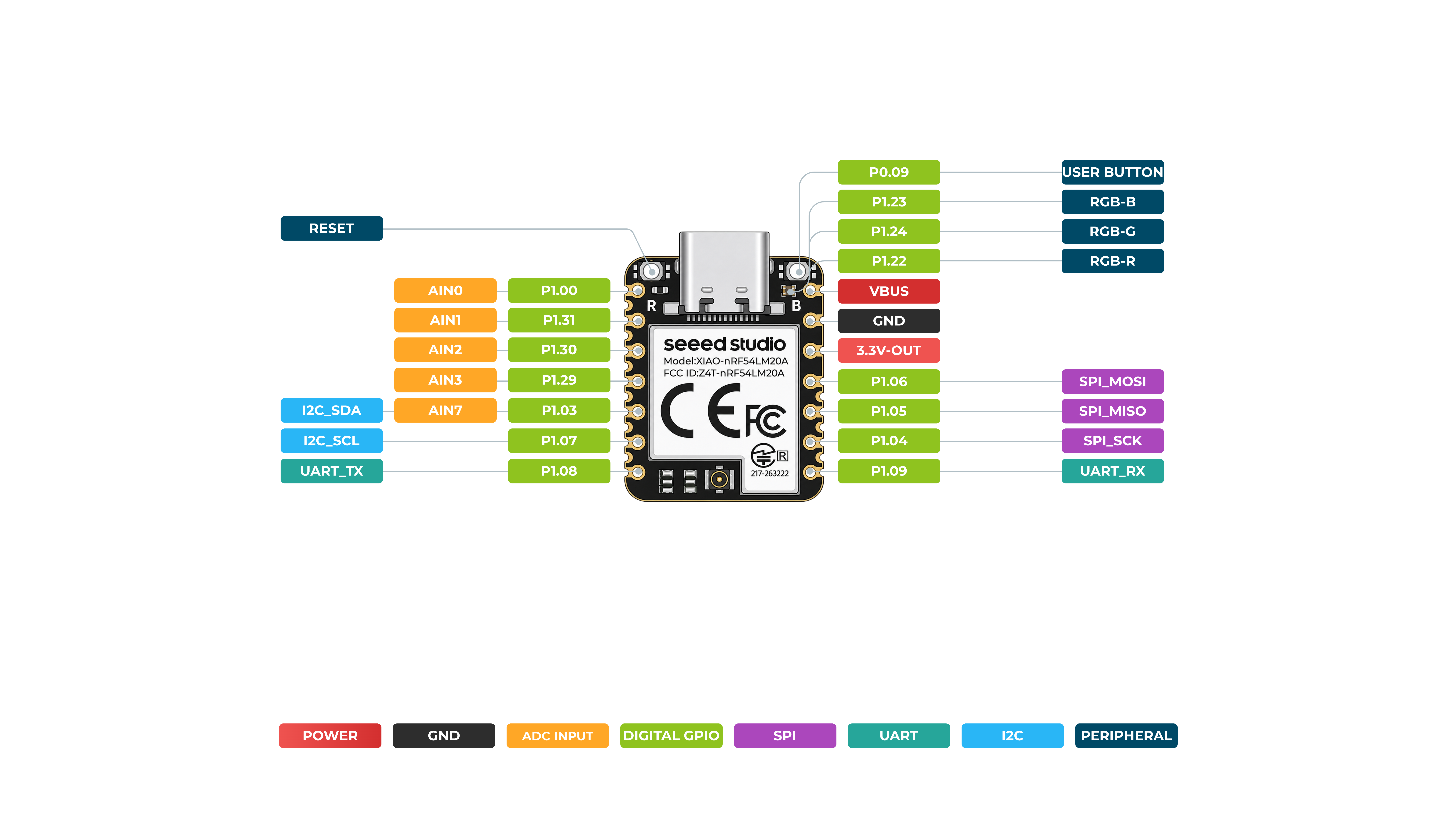
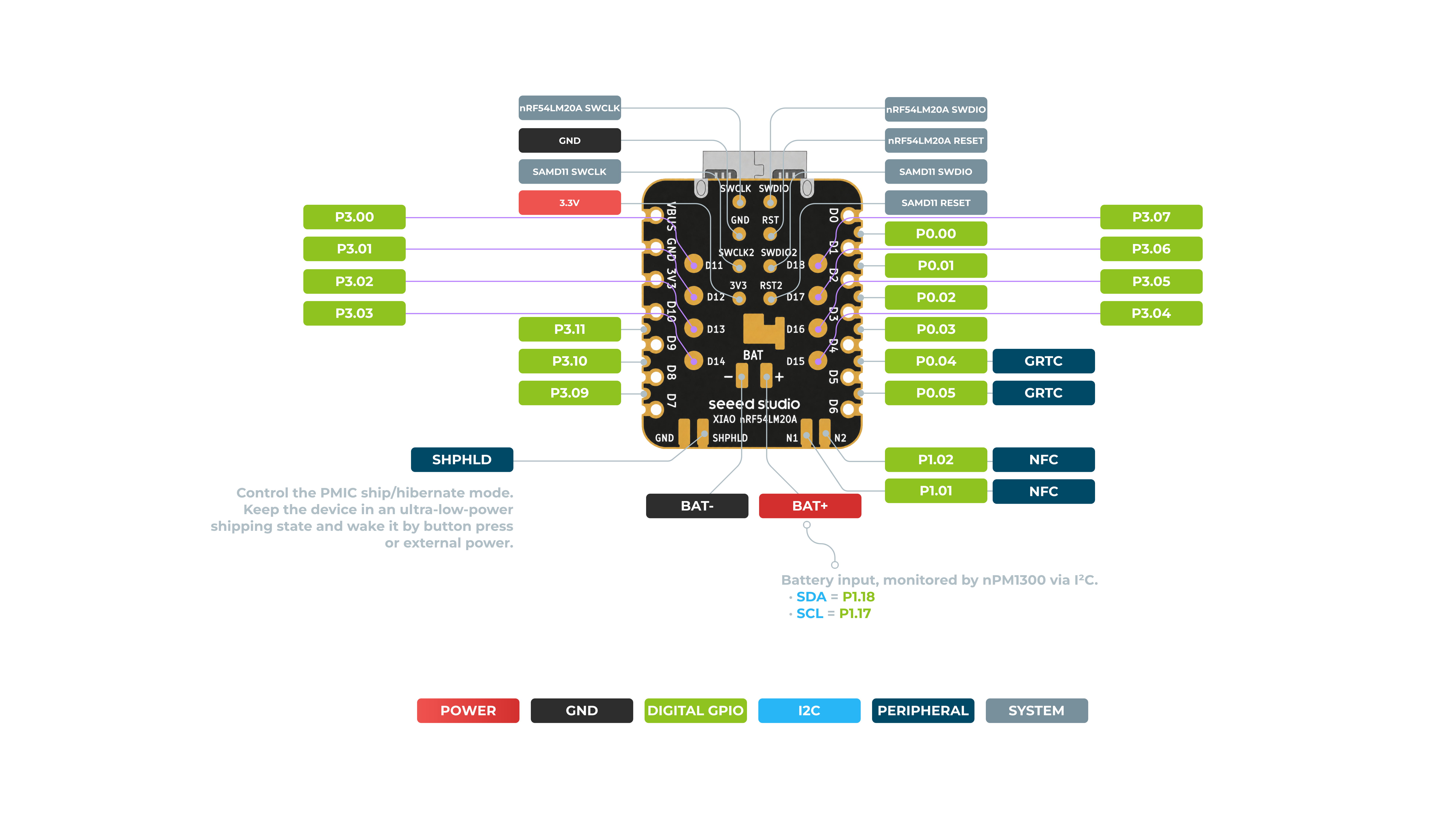
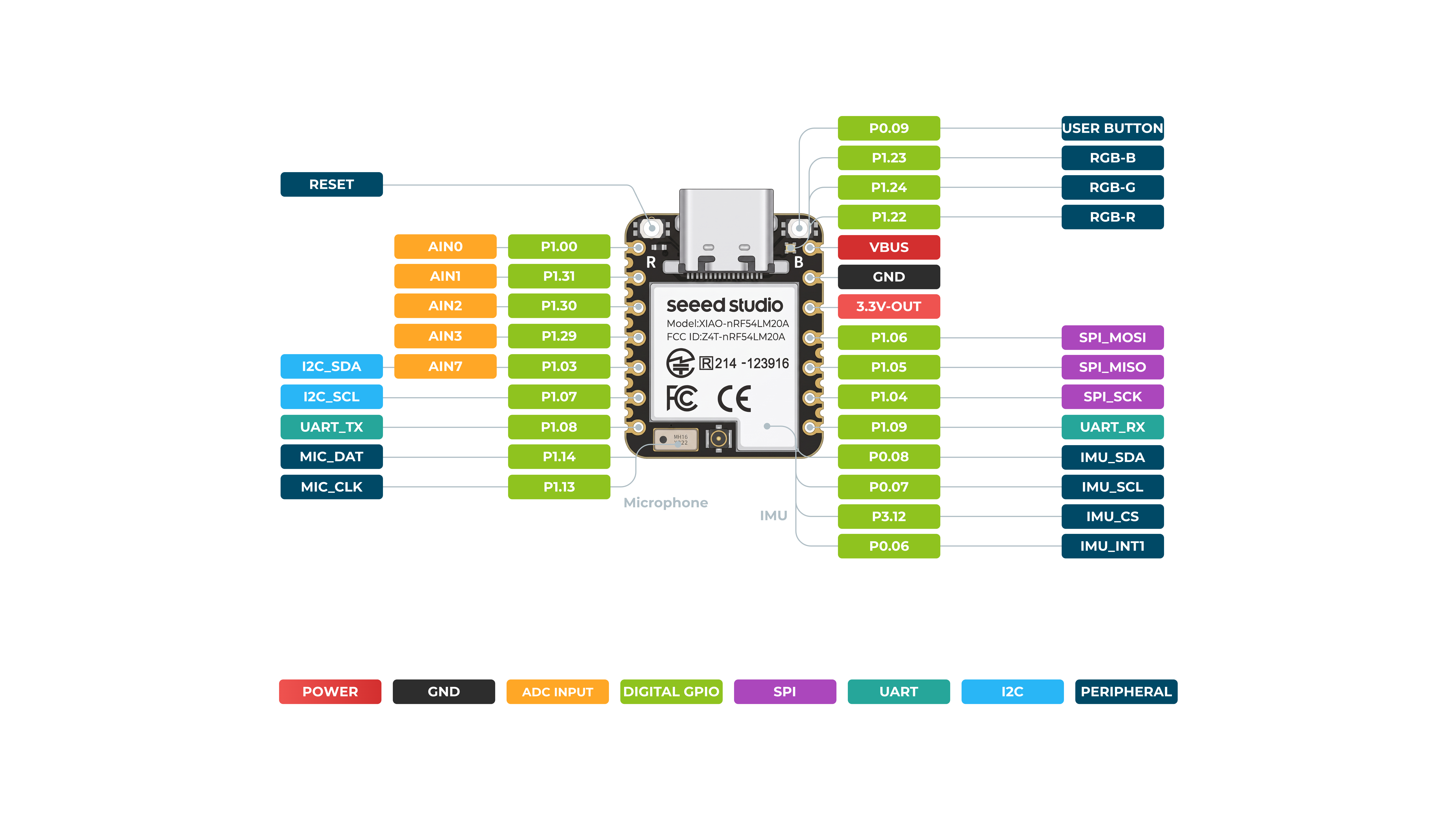

Pin Map
| XIAO Pin | Function | Chip Pin | Description |
|---|---|---|---|
| Power Pins | |||
| VBUS | VBUS | - | 5V Power Input/Output |
| GND | GND | - | Ground |
| 3V3 | 3V3-OUT | - | 3.3V Power Output |
| BAT+ | BAT+ | - | Battery Input (monitored by nPM1300 via I²C) |
| BAT- | BAT- | - | Battery Negative Terminal |
| SHPHLD | SHPHLD | - | PMIC Ship/Hibernate Mode Control (ultra-low-power shipping state) |
| System & Control Pins | |||
| RESET | RESET | - | Board Reset |
| SWCLK | SWCLK | nRF54LM20A SWCLK / SAMD11 SWCLK | Serial Wire Clock (for nRF54 and SAMD11) |
| SWDIO | SWDIO | nRF54LM20A SWDIO / SAMD11 SWDIO | Serial Wire Data (for nRF54 and SAMD11) |
| SAMD11_RESET | RESET | SAMD11 RESET | SAMD11 Co-processor Reset |
| User & LED Pins | |||
| - | USER_BUTTON | P0.09 | User Button Input |
| - | RGB-B | P1.23 | Onboard RGB LED Blue Channel |
| - | RGB-G | P1.24 | Onboard RGB LED Green Channel |
| - | RGB-R | P1.22 | Onboard RGB LED Red Channel |
| Analog Input (ADC) Pins | |||
| A0 | AIN0 | P1.00 | Analog Input 0 / GPIO |
| A1 | AIN1 | P1.31 | Analog Input 1 / GPIO |
| A2 | AIN2 | P1.30 | Analog Input 2 / GPIO |
| A3 | AIN3 | P1.29 | Analog Input 3 / GPIO |
| A7 | AIN7 | P1.03 | Analog Input 7 / GPIO |
| I2C Pins | |||
| SDA | I2C_SDA | P1.03 | I2C Data Line (IMU & Peripheral) |
| SCL | I2C_SCL | P1.07 | I2C Clock Line (IMU & Peripheral) |
| - | BAT_SDA | P1.18 | Battery Monitor I2C SDA (nPM1300) |
| - | BAT_SCL | P1.17 | Battery Monitor I2C SCL (nPM1300) |
| UART Pins | |||
| TX | UART_TX | P1.08 | UART Transmit |
| RX | UART_RX | P1.09 | UART Receive |
| SPI Pins | |||
| MOSI | SPI_MOSI | P1.06 | SPI Master Out Slave In |
| MISO | SPI_MISO | P1.05 | SPI Master In Slave Out |
| SCK | SPI_SCK | P1.04 | SPI Serial Clock |
| Onboard Peripheral Pins | |||
| - | MIC_DAT | P1.14 | Microphone Data Line |
| - | MIC_CLK | P1.13 | Microphone Clock Line |
| - | IMU_SDA | P0.08 | IMU I2C SDA (Onboard IMU) |
| - | IMU_SCL | P0.07 | IMU I2C SCL (Onboard IMU) |
| - | IMU_CS | P3.12 | IMU Chip Select |
| - | IMU_INT1 | P0.06 | IMU Interrupt 1 |
| - | NFC | P1.02 / P1.01 | NFC Antenna Pins |
| - | GRTC | P0.04 / P0.05 | General Purpose RTC Pins |
Getting Started With PlatformIO
In this section, we will guide you to quickly get started with the XIAO nRF54LM20A through the multi-color blinking effect of an RGB LED. Please complete the hardware and software preparations below to set up your XIAO for subsequent development.
Hardware Preperation
You need to prepare the following:
- 1 x Seeed Studio XIAO nRF54LM20A Sense
- 1 x Computer
- 1 x USB Type-C cable
| Seeed Studio XIAO nRF54LM20A Sense |
|---|
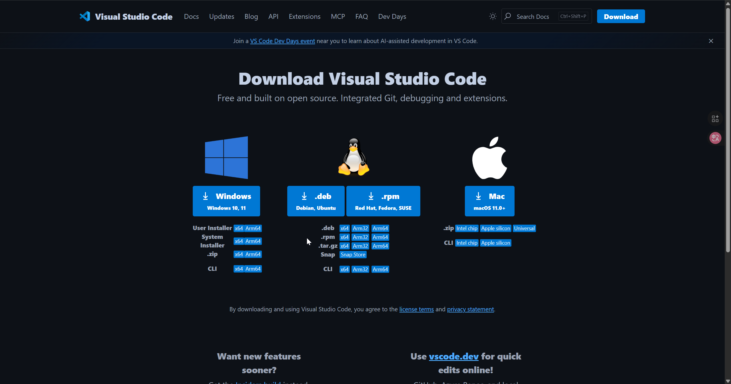
Download VS Code
Download according to the system you are using VS Code
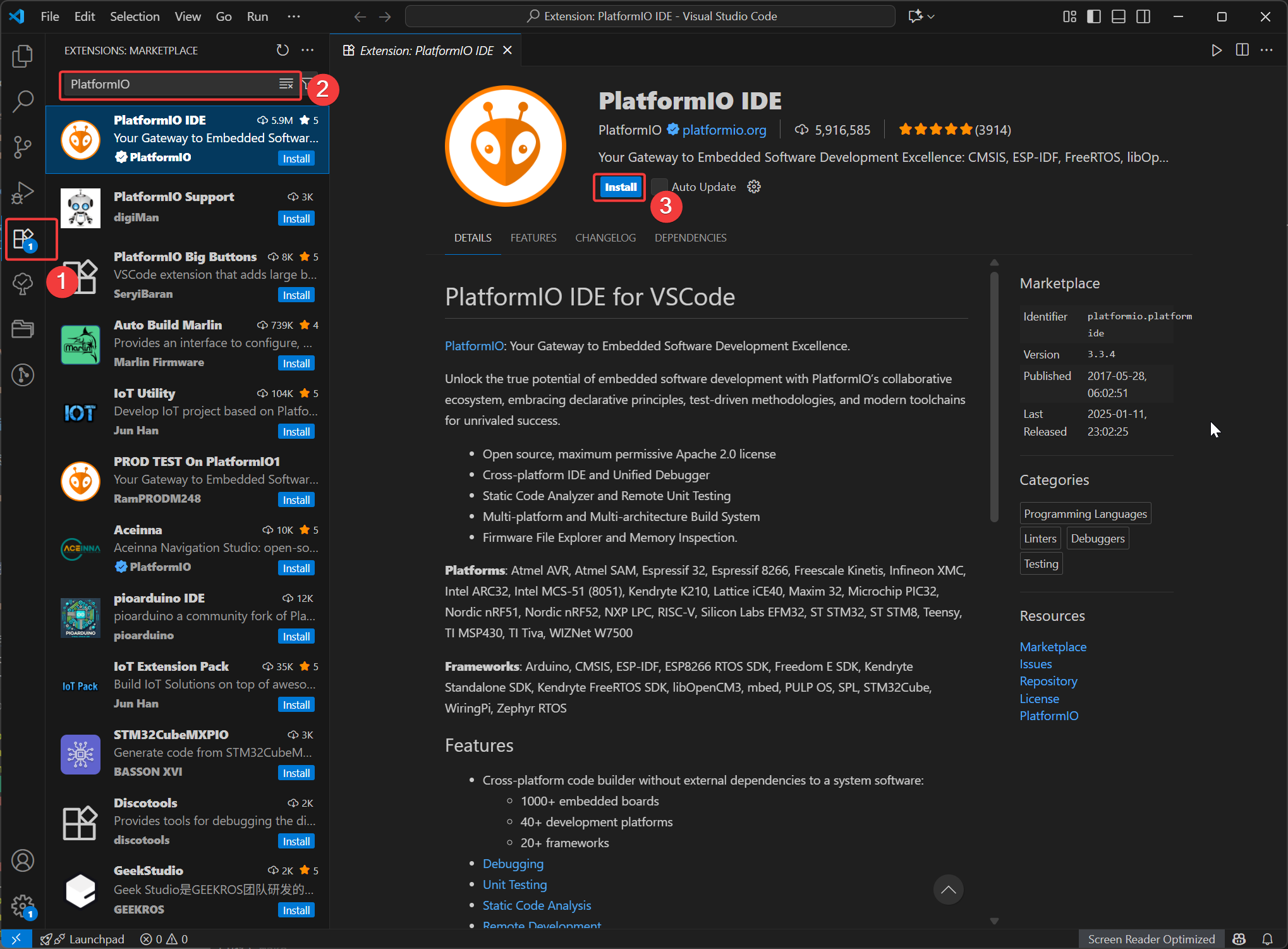
Install the PlatformIO extension
Open VSCode, click on Extensions, then search for PlatformIO and select to install. After the installation is complete, restart VSCode.
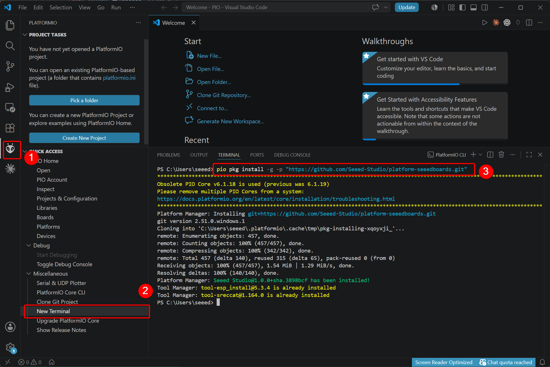
Install the platform-seeedboards platform package
The Seeed Studio XIAO series boards use a custom PlatformIO platform, so you need to install the corresponding platform package manually.
- Run the following command for a fresh installation:
pio pkg install -g -p "https://github.com/Seeed-Studio/platform-seeedboards.git"
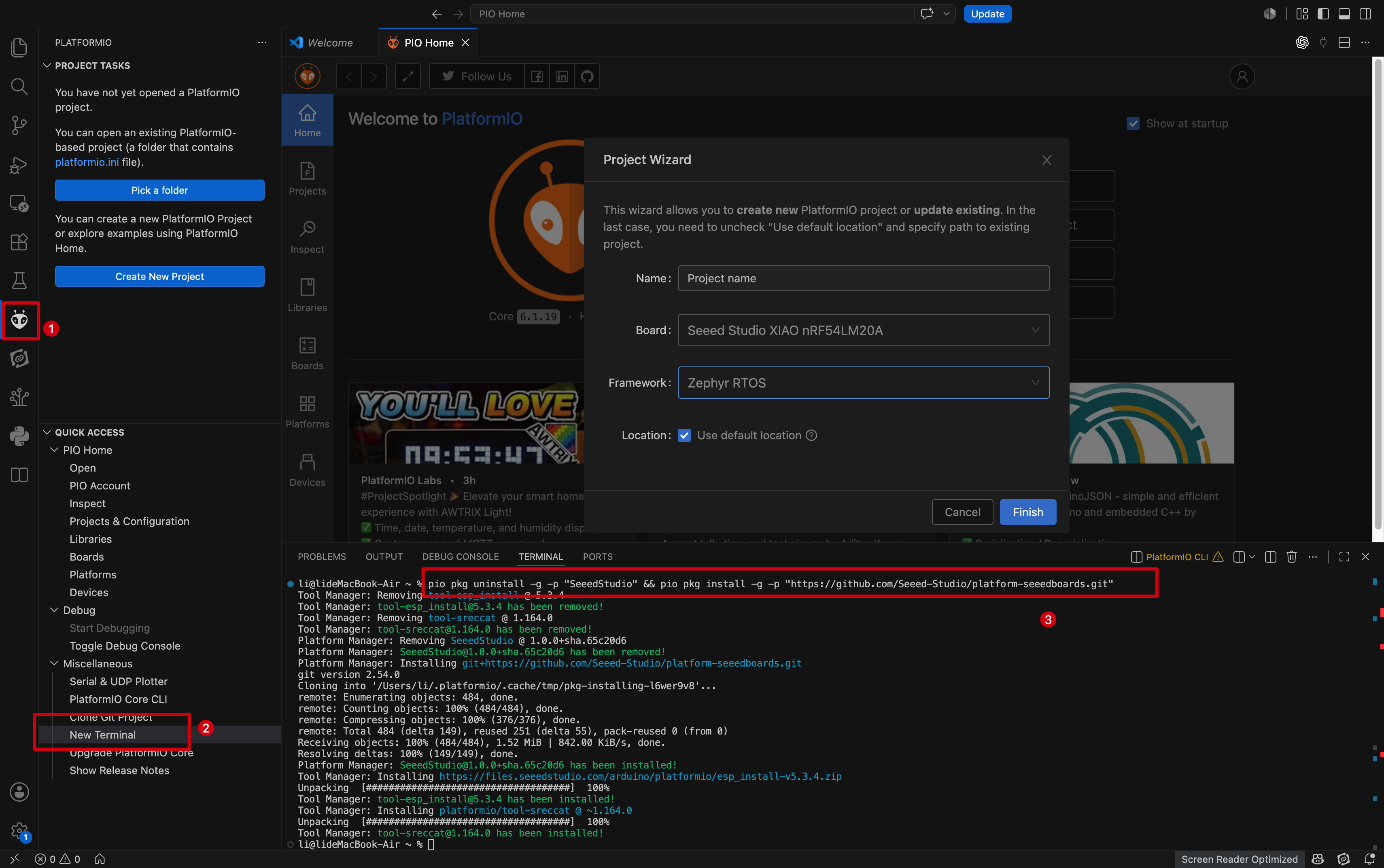
- If you have previously used Seeed Studio XIAO series boards in PlatformIO, run the command below to update:
pio pkg uninstall -g -p "SeeedStudio" && pio pkg install -g -p "SeeedStudio=https://github.com/Seeed-Studio/platform-seeedboards.git" --force
If you want to use an existing PlatformIO project, replace the content of platformio.ini as follows:
[env:seeed-xiao-nrf54lm20a]
platform = https://github.com/Seeed-Studio/platform-seeedboards.git
framework = zephyr
board = seeed-xiao-nrf54lm20a
Create New Project
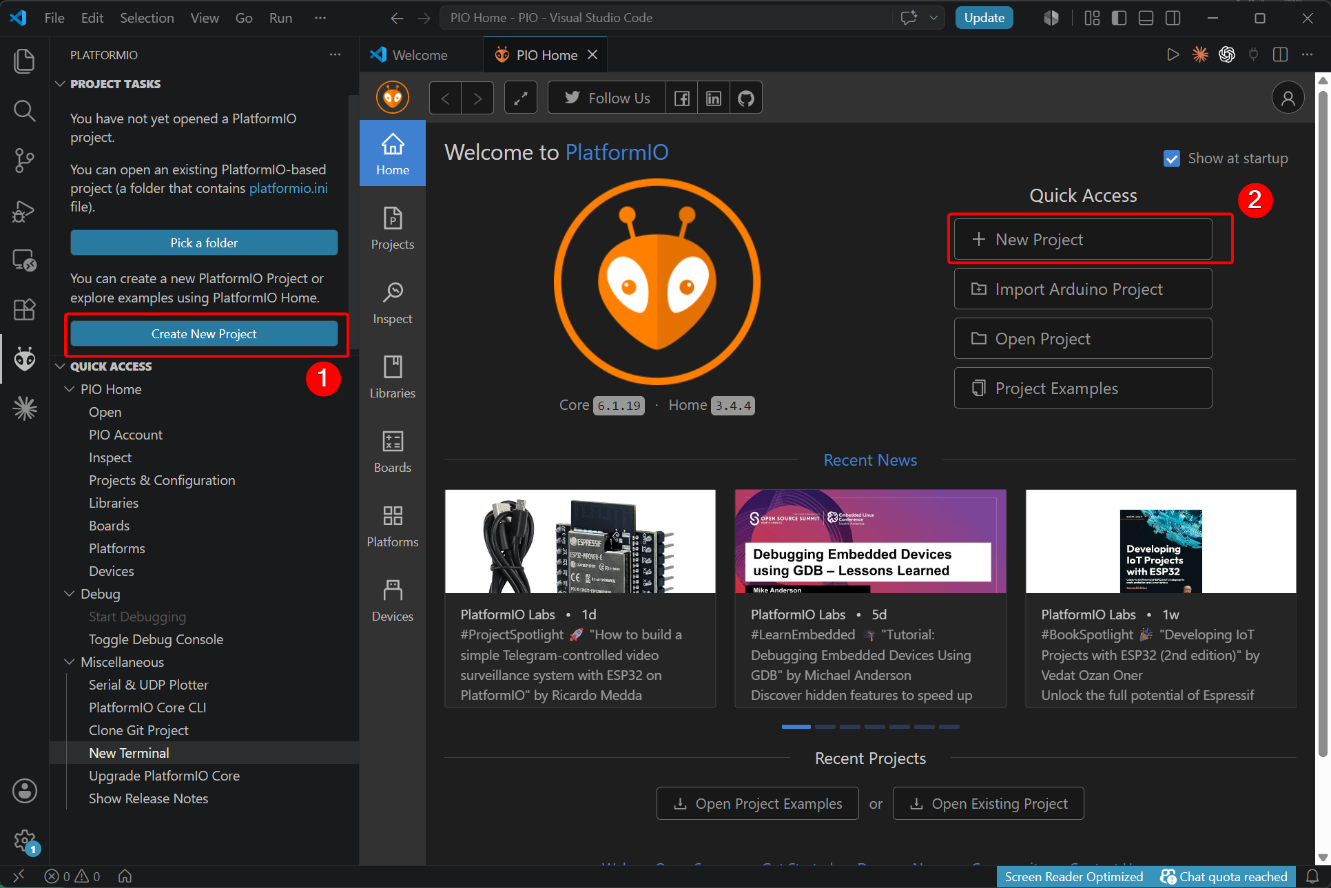
- Open the PlatformIO extension and select Create New Project.
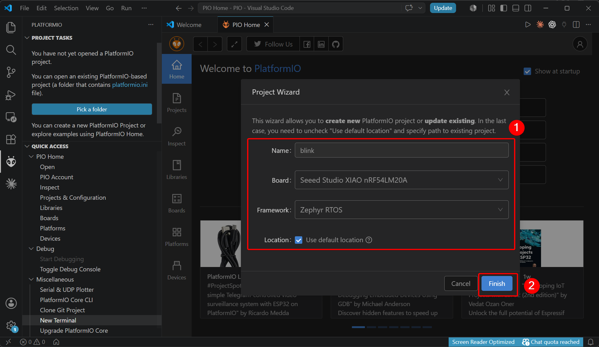
- Set the project name, select the development board, framework and file storage path.
- After creation completes, a prompt to open the workspace will pop up. Click OK.
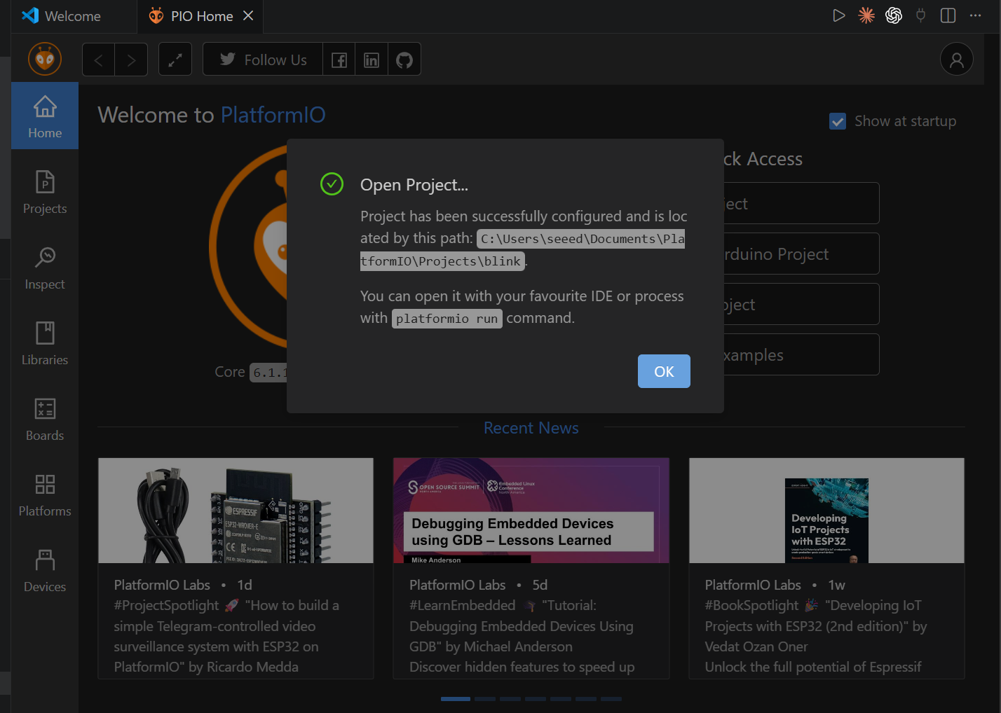
- Navigate to the project folder. Files are stored in the default directory if you did not specify a custom path.
- For Windows Default:
<path>: C:\Users\your_name\Documents\PlatformIO\Projects
- For Mac / Linux Default:
<path>: ~/Documents/PlatformIO/Projects
Add the Blink program
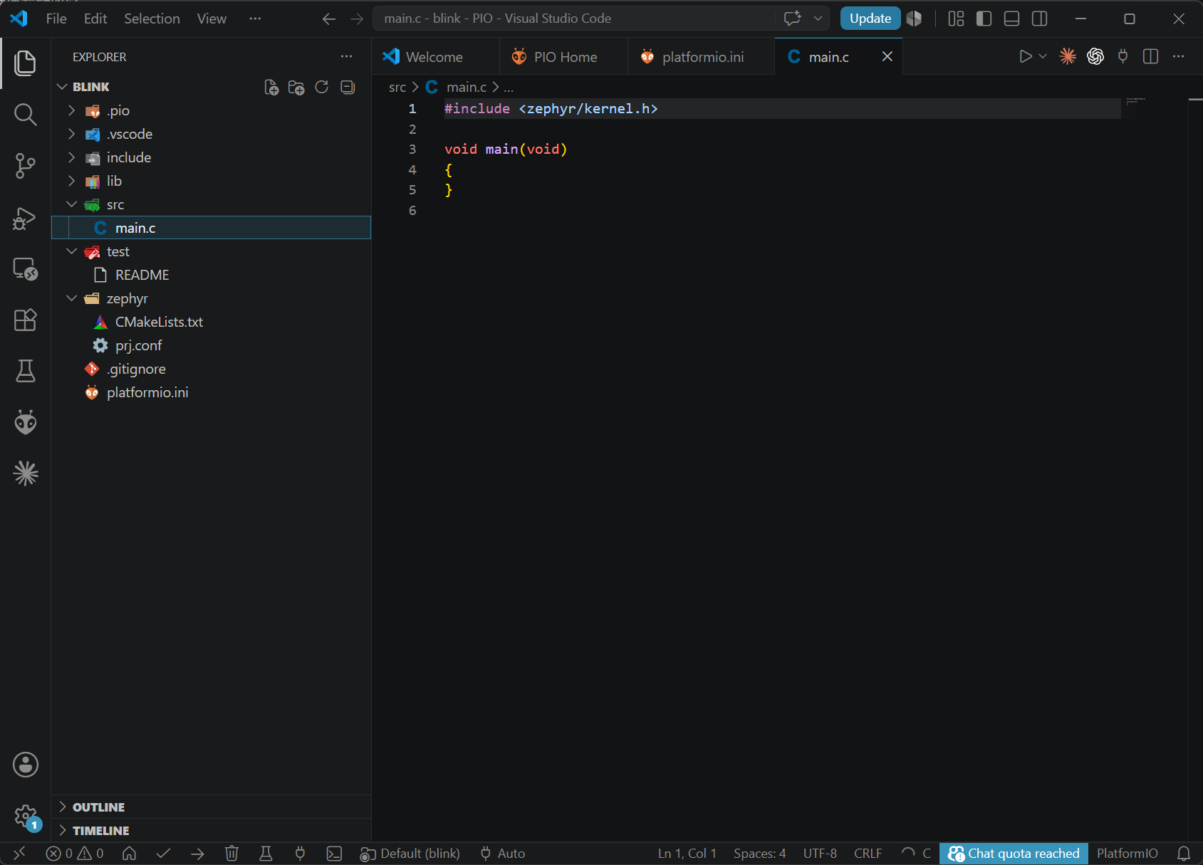
This tutorial is developed based on Zephyr RTOS. The project consists of three core files:
main.c: Main program that contains the application logic.app.overlay: Devicetree overlay file for hardware peripheral configuration.prj.conf: Project configuration file to enable required Zephyr modules.
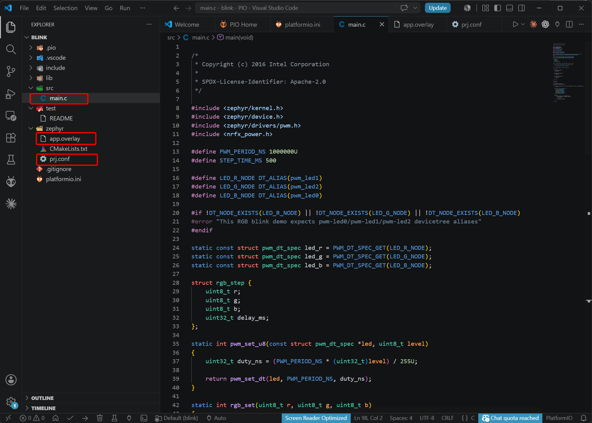
- Add the main.c program
main.c
/*
 * Copyright (c) 2016 Intel Corporation
 *
 * SPDX-License-Identifier: Apache-2.0
 */

#include <zephyr/kernel.h>
#include <zephyr/device.h>
#include <zephyr/drivers/pwm.h>
#include <nrfx_power.h>

#define PWM_PERIOD_NS 1000000U
#define STEP_TIME_MS 500

#define LED_R_NODE DT_ALIAS(pwm_led1)
#define LED_G_NODE DT_ALIAS(pwm_led2)
#define LED_B_NODE DT_ALIAS(pwm_led0)

#if !DT_NODE_EXISTS(LED_R_NODE) || !DT_NODE_EXISTS(LED_G_NODE) || !DT_NODE_EXISTS(LED_B_NODE)
#error "This RGB blink demo expects pwm-led0/pwm-led1/pwm-led2 devicetree aliases"
#endif

static const struct pwm_dt_spec led_r = PWM_DT_SPEC_GET(LED_R_NODE);
static const struct pwm_dt_spec led_g = PWM_DT_SPEC_GET(LED_G_NODE);
static const struct pwm_dt_spec led_b = PWM_DT_SPEC_GET(LED_B_NODE);

struct rgb_step {
	uint8_t r;
	uint8_t g;
	uint8_t b;
	uint32_t delay_ms;
};

static int pwm_set_u8(const struct pwm_dt_spec *led, uint8_t level)
{
	uint32_t duty_ns = (PWM_PERIOD_NS * (uint32_t)level) / 255U;

	return pwm_set_dt(led, PWM_PERIOD_NS, duty_ns);
}

static int rgb_set(uint8_t r, uint8_t g, uint8_t b)
{
	int ret;

	ret = pwm_set_u8(&led_r, r);
	if (ret < 0) {
		return ret;
	}

	ret = pwm_set_u8(&led_g, g);
	if (ret < 0) {
		return ret;
	}

	ret = pwm_set_u8(&led_b, b);
	if (ret < 0) {
		return ret;
	}

	return 0;
}

int main(void)
{
	int ret;

#if defined(CONFIG_NRFX_POWER)
	nrfx_power_constlat_mode_request();
#endif

	if (!device_is_ready(led_r.dev) || !device_is_ready(led_g.dev) || !device_is_ready(led_b.dev)) {
		return -1;
	}

	static const struct rgb_step demo[] = {
		{ 255, 0, 0, STEP_TIME_MS },
		{ 0, 255, 0, STEP_TIME_MS },
		{ 0, 0, 255, STEP_TIME_MS },
		{ 255, 255, 0, STEP_TIME_MS },
		{ 0, 255, 255, STEP_TIME_MS },
		{ 255, 0, 255, STEP_TIME_MS },
		{ 255, 255, 255, STEP_TIME_MS },
		{ 0, 0, 0, STEP_TIME_MS },
	};

	while (1) {
		for (size_t i = 0; i < ARRAY_SIZE(demo); i++) {
			ret = rgb_set(demo[i].r, demo[i].g, demo[i].b);
			if (ret < 0) {
				return ret;
			}
			k_msleep(demo[i].delay_ms);
		}
	}

	return 0;
}
- Add the app.overlay file
The devicetree overlay file does not exist in the newly created blank sample. You need to add it under the zephyr directory.
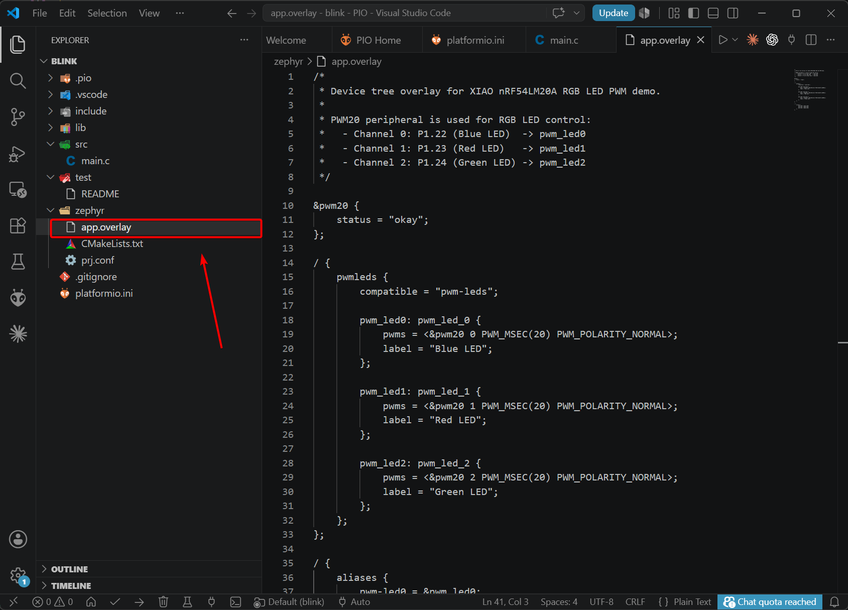
app.overlay
/*
 * Device tree overlay for XIAO nRF54LM20A RGB LED PWM demo.
 *
 * PWM20 peripheral is used for RGB LED control:
 *   - Channel 0: P1.22 (Blue LED)  -> pwm_led0
 *   - Channel 1: P1.23 (Red LED)   -> pwm_led1
 *   - Channel 2: P1.24 (Green LED) -> pwm_led2
 */

&pwm20 {
	status = "okay";
};

/ {
	pwmleds {
		compatible = "pwm-leds";

		pwm_led0: pwm_led_0 {
			pwms = <&pwm20 0 PWM_MSEC(20) PWM_POLARITY_NORMAL>;
			label = "Blue LED";
		};

		pwm_led1: pwm_led_1 {
			pwms = <&pwm20 1 PWM_MSEC(20) PWM_POLARITY_NORMAL>;
			label = "Red LED";
		};

		pwm_led2: pwm_led_2 {
			pwms = <&pwm20 2 PWM_MSEC(20) PWM_POLARITY_NORMAL>;
			label = "Green LED";
		};
	};
};

/ {
	aliases {
		pwm-led0 = &pwm_led0;
		pwm-led1 = &pwm_led1;
		pwm-led2 = &pwm_led2;
	};
};
- Modify
prj.confand enable the corresponding configurations.
CONFIG_GPIO=y
CONFIG_PWM=y
CONFIG_SERIAL=n
Compile and upload the program
Two methods for compilation and uploading are introduced below.
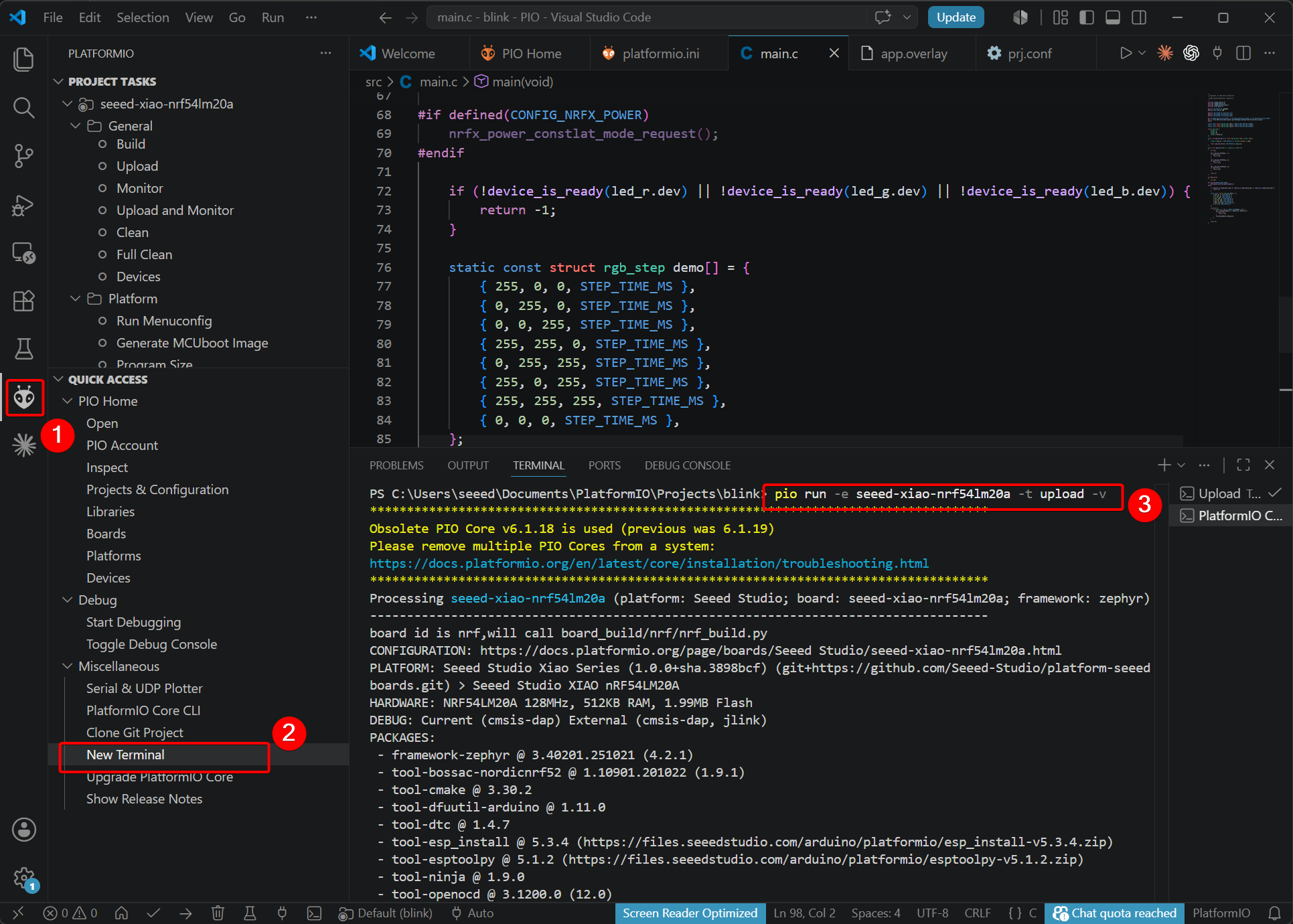
- Compile & Upload via Button
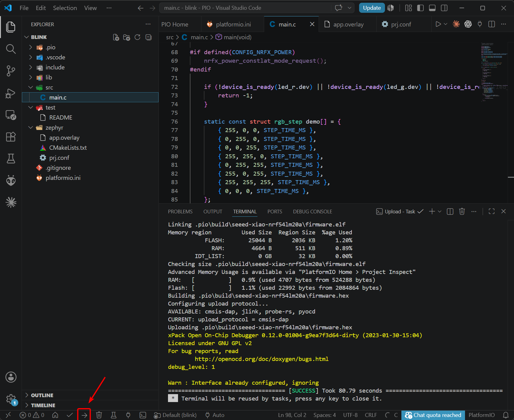
- Compile & Upload via Command Line
pio run -e seeed-xiao-nrf54lm20a -t upload -v
Observe the Result
Bluetooth Antenna
This board uses an external Bluetooth antenna. To ensure a better quality of Bluetooth signal and enhance your Bluetooth usage experience, it is recommended to install a Bluetooth antenna. The connection method is shown below:
Battery Usage
The XIAO nRF54LM20A is capable of using a 3.7V lithium battery as the power supply input. You can refer to the following diagram for the wiring method.
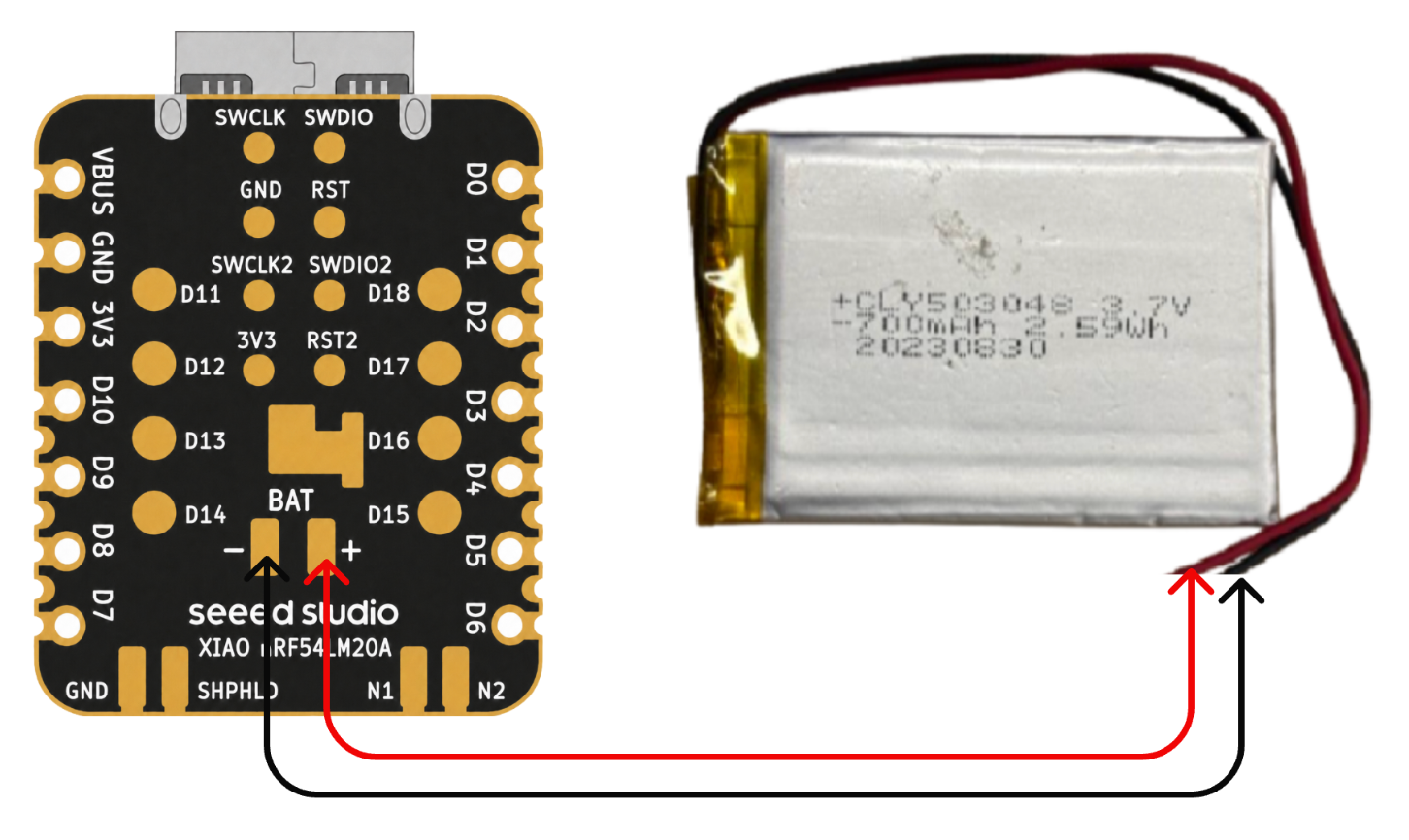
Please be careful not to short-circuit the positive and negative terminals and burn the battery and equipment when soldering. If the battery has power, never solder it onto the board, as this may burn out the circuit board. Short-circuiting while the circuit is powered on poses a significant risk; it is recommended to use an adapter.
Instructions on the use of batteries:
- Please use qualified batteries that meet the specifications.
- XIAO can be connected to your computer device via data cable while using the battery, rest assured that XIAO has a built-in circuit protection chip, which is safe.
Battery Voltage Detection
The XIAO nRF54LM20A integrates a battery voltage detection feature that centers on efficiently managing battery power measurements using the nPM1300-CAA load switch. This guide will focus on analyzing the software implementation of the battery detection (especially the main.c code) and guide you on how to easily deploy and use this feature in a PlatformIO environment, avoiding the complexity of the Zephyr NCS SDK.
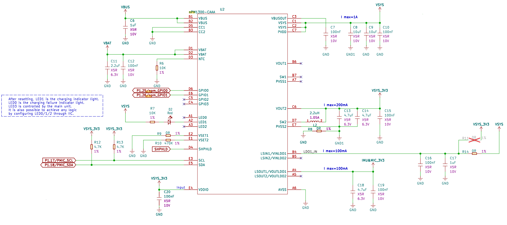
Detecting Battery Schematic
What the nPM1300-CAA chip does:
nPM1300-CAA is a highly integrated power management IC (PMIC) that replaces the simple load switch function of the TPS22916. It not only controls battery voltage switching for low-power monitoring but also integrates charging, regulation, and precise fuel gauging (via voltage, current, temperature) to maximize battery life for the nRF54LM20A.
The following example works for both PlatformIO and nRF Connect SDK. It can be used directly in PlatformIO, while the SDK requires manually adding files. Refer to this link
Peripherals Overview
The peripheral circuitry on this board includes an IMU and a microphone. You can see their locations in the diagram below:
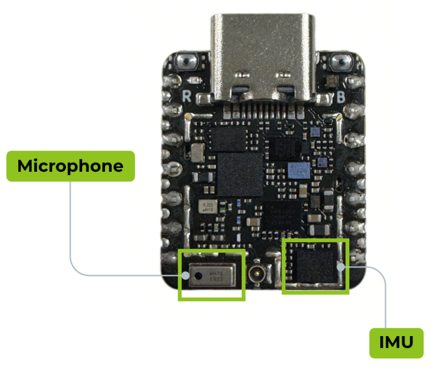
IMU
The XIAO nRF54LM20A Sense features an LSM6DS3TR-C IMU with a 3-axis accelerometer and a 3-axis gyroscope.
MIC
The XIAO nRF54LM20A Sense is equipped with an MSM261DGT006 digital microphone for audio capture.
FAQ
Q1: What should I do if I encounter build errors after modifying the configuration files?
If you previously built the project and then modified configuration files (such as prj.conf, app.overlay, or CMakeLists.txt), it is recommended to clean the build cache before rebuilding. This helps avoid compilation errors caused by stale or corrupted cache files.
Run the following command:
pio run -t clean
Q2: Why do I get zsh: command not found: openocd after installation? (macOS)
This issue usually occurs because the OpenOCD executable directory has not been added to your system PATH. You can permanently add it to your ~/.zshrc file using the following commands.
Note: This solution is for macOS only.
echo 'export PATH="$HOME/Library/Application Support/Seeed/OpenOCD/tool-openocd/bin:$PATH"' >> ~/.zshrc
source ~/.zshrc
openocd --version
If the version number is displayed successfully, the configuration has been completed.
Q3: What should I do if the PlatformIO project dropdown fails after installing the Seeed Studio XIAO platform multiple times?
If you have installed different versions of the Seeed Studio XIAO PlatformIO platform multiple times, duplicate or outdated platform packages may cause version conflicts and prevent PlatformIO projects from loading correctly.
It is recommended to remove all old Seeed platform packages and let PlatformIO download the latest official version automatically.
Run the following command:
rm -rf ~/.platformio/packages/platform-seeed-* ~/.platformio/packages/framework-seeed-*
After cleaning up, reopen PlatformIO and rebuild your project.
Resources
Seeed Studio XIAO nRF54LM20A
Hardware Design
- 📄[Datasheet] Nordic nRF54LM20A Datasheet
- 📄[Schematic] XIAO nRF54LM20A Schematic
- 🗃️[PCB Design Files] XIAO nRF54LM20A KiCad Project
- 🗃️[PCB Design Libraries]
- 📄[Pinout Diagram]XIAO nRF54LM20A Pinout Sheet
Seeed Studio XIAO nRF54LM20A Sense
Hardware Design
- 📄[Datasheet] Nordic nRF54LM20A Datasheet
- 📄[Schematic] XIAO nRF54LM20A Sense Schematic
- 🗃️[PCB Design Files] XIAO nRF54LM20A KiCad Project
- 🗃️[PCB Design Libraries]
- 📄[Pinout Diagram]XIAO nRF54LM20A Sense Pinout Sheet
Tech Support & Product Discussion
Thank you for choosing our products! We are here to provide you with different support to ensure that your experience with our products is as smooth as possible. We offer several communication channels to cater to different preferences and needs.