Pin Multiplexing with Seeed Studio XIAO nRF54LM20A Sense
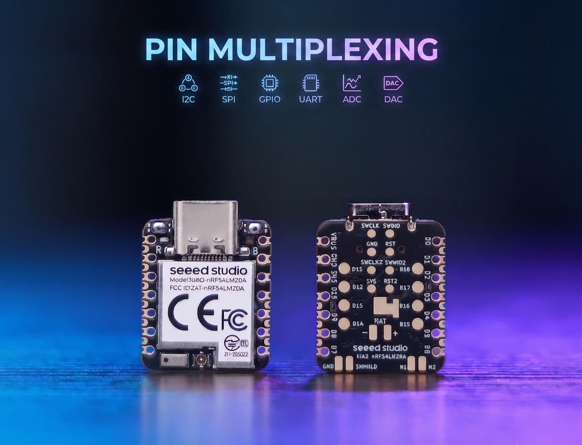
The XIAO nRF54LM20A features abundant pin resources and natively supports development with various standard peripheral interfaces including Digital, Analog, SPI and IIC. This article demonstrates relevant implementations with practical application cases.
This tutorial is developed based on the PlatformIO build system and Zephyr RTOS. If you are not familiar with creating a project for the XIAO nRF54LM20A under PlatformIO, you can jump to Getting Sarted With Seeed Studio XIAO nRF54LM20A Sense
Digital
Digital pins mainly realize on-off control of external sensors and actuators by outputting high and low logic levels. Combined with the Grove Base for XIAO expansion board and standard Grove peripheral modules, this section elaborates on the underlying driver logic and practical invocation methods of digital pins on XIAO nRF54LM20A in detail.
Hardware Preparation
| Seeed Studio XIAO nRF54LM20A Sense | Seeed Studio Grove Base for XIAO | Grove - Piezo Buzzer | Grove - Button |
|---|---|---|---|
 |  |  | |
Software Preparation
According to the pinout of the XIAO nRF54LM20A, P1.0 can be selected as the control pin for the Grove-Button, and P1.31 can be selected as the control pin for the Grove-Pizero Buzzer.
- For the pinout of the XIAO nRF54LM20A,click XIAO nRF54LM20A Pin List to view details.
Write the program for main.c
/*
 * Grove Button (P1.0) + Grove Buzzer (P1.31) - Digital mode
 * Button pressed → Buzzer ON; Button released → Buzzer OFF
 *
 * NOTE: Requires an ACTIVE buzzer (built-in oscillator).
 *       A passive piezo buzzer needs PWM — use plan B instead.
 */

#include <zephyr/kernel.h>
#include <zephyr/device.h>
#include <zephyr/drivers/gpio.h>
#include <zephyr/sys/printk.h>

#define BUTTON_PIN 0  /* P1.0 - Grove Button - D0 */
#define BUZZER_PIN 31 /* P1.31 - Grove Buzzer - D1 */

int main(void)
{
	const struct device *gpio1_dev = DEVICE_DT_GET(DT_NODELABEL(gpio1));

	printk("=== Grove Button + Buzzer (Digital Mode) ===\n");

	if (!device_is_ready(gpio1_dev))
	{
		printk("ERROR: gpio1 device is not ready!\n");
		return -1;
	}
	printk("gpio1 device ready: %s\n", gpio1_dev->name);

	/* Grove Button has onboard pull-down; HIGH = pressed */
	gpio_pin_configure(gpio1_dev, BUTTON_PIN, GPIO_INPUT);

	/* Buzzer: HIGH = on */
	gpio_pin_configure(gpio1_dev, BUZZER_PIN, GPIO_OUTPUT_INACTIVE);

	printk("Button:  P1.%d (input)\n", BUTTON_PIN);
	printk("Buzzer:  P1.%d (output)\n", BUZZER_PIN);
	printk("Press the button to turn on the buzzer...\n");

	int last_val = 0;

	while (1)
	{
		int val = gpio_pin_get(gpio1_dev, BUTTON_PIN);
		if (val >= 0)
		{
			gpio_pin_set(gpio1_dev, BUZZER_PIN, val);

			/* Only print on state change to avoid log spam */
			if (val != last_val)
			{
				printk("Button %s → Buzzer %s\n",
				       val ? "PRESSED " : "released",
				       val ? "ON" : "OFF");
				last_val = val;
			}
		}
		k_msleep(10);
	}

	return 0;
}
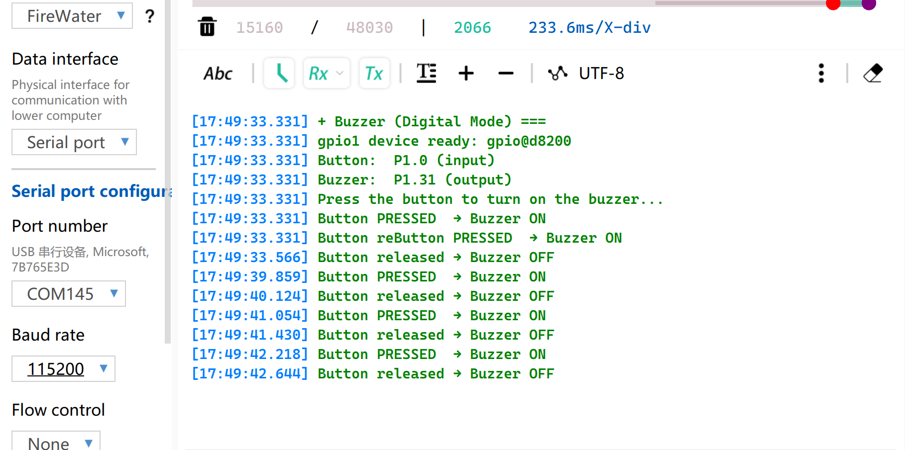
Result
After flashing the firmware, press the button and the buzzer will beep.And Serial port will print the status.
Note to set the baud rate to 115200. If you directly open Monitor in VS, it is recommended to set the baud rate in the .ini file
PWM
PWM is a timing waveform output function implemented based on digital output GPIOs. It rapidly switches pin levels at a fixed frequency and dynamically adjusts the duty cycle of high level within a single cycle, so as to output equivalent analog signals to peripherals. In practical engineering applications, PWM is widely used for precise angle control of servo motors and smooth brightness adjustment of LEDs.
Hardware Preparation
| Seeed Studio XIAO nRF54LM20A Sense | Seeed Studio Grove Base for XIAO | Grove - Servo |
|---|---|---|
|  | |
Software Preparation
According to the pinout of the XIAO nRF54LM20A, P1.0 can be selected as the control pin for the Grove-Servo.
- For the pinout of the XIAO nRF54LM20A,click XIAO nRF54LM20A Pin List to view details.
- Modify the device tree file
app.overlay. For the PWM output function, the hardware instance must be explicitly bound to thepwm20,pwm21, orpwm22node. The system default UART console output is attached to theuart20node.
app.overlay
/*
 * UART20 (console) + PWM20 (servo) configuration for XIAO nRF54LM20A.
 *
 * Note: spi23 and uart20 share the same peripheral instance (0xc6000),
 * so only one can be active at a time. SD card via spi23 is removed here.
 */

/ {
	chosen {
		zephyr,console    = &uart20;
		nordic,rpc-uart   = &uart20;
		zephyr,shell-uart = &uart20;
	};
};

/* ── UART20 (console, TX: P1.11 / RX: P1.10) ── */
&uart20 {
	current-speed = <115200>;
	status = "okay";
};

&uart20_default {
	group1 {
		psels = <NRF_PSEL(UART_TX, 1, 11)>;
	};
	group2 {
		psels = <NRF_PSEL(UART_RX, 1, 10)>;
		bias-pull-up;
	};
};

&uart20_sleep {
	group1 {
		psels = <NRF_PSEL(UART_TX, 1, 11)>,
			<NRF_PSEL(UART_RX, 1, 10)>;
		low-power-enable;
	};
};

/* ── PWM20 (servo, P1.0) ── */
&pwm20 {
	status = "okay";
	pinctrl-0 = <&servo_pwm20_default>;
	pinctrl-1 = <&servo_pwm20_sleep>;
	pinctrl-names = "default", "sleep";
};

&pinctrl {
	servo_pwm20_default: servo_pwm20_default {
		group1 {
			psels = <NRF_PSEL(PWM_OUT0, 1, 0)>; /* P1.0 */
		};
	};
	servo_pwm20_sleep: servo_pwm20_sleep {
		group1 {
			psels = <NRF_PSEL(PWM_OUT0, 1, 0)>;
			low-power-enable;
		};
	};
};
- Modify the
prj.conffile to enable relevant PWM configurations.
CONFIG_PWM=y
CONFIG_SERIAL=y
CONFIG_PRINTK=y
CONFIG_UART_CONSOLE=y
- Write the main.c program to implement PWM servo control function and configure parameters such as PWM period.
/*
 * Servo control on P1.0 via PWM (50 Hz).
 * Sweeps 0→180° at ~100°/s, then returns 180→0° at ~33°/s.
 * Current angle is printed to serial console.
 */

#include <zephyr/kernel.h>
#include <zephyr/device.h>
#include <zephyr/drivers/pwm.h>
#include <zephyr/sys/printk.h>

/* Standard servo: 50 Hz period, 0.5–2.5 ms pulse for 0–180° */
#define SERVO_PERIOD_NS PWM_MSEC(20)
#define SERVO_MIN_NS PWM_USEC(500)
#define SERVO_MAX_NS PWM_USEC(2500)

#define SERVO_CHANNEL 0

/* 10 ms/step → ~100°/s forward; 30 ms/step → ~33°/s return */
#define STEP_FWD_MS 30
#define STEP_RET_MS 30

static const struct device *pwm_dev = DEVICE_DT_GET(DT_NODELABEL(pwm20));

static int set_angle(int degrees)
{
    uint32_t pulse = SERVO_MIN_NS +
                     (uint32_t)((uint64_t)degrees *
                                (SERVO_MAX_NS - SERVO_MIN_NS) / 180U);
    return pwm_set(pwm_dev, SERVO_CHANNEL, SERVO_PERIOD_NS, pulse,
                   PWM_POLARITY_NORMAL);
}

int main(void)
{
    printk("=== boot ===\n");

    if (!device_is_ready(pwm_dev))
    {
        printk("Error: PWM device not ready\n");
        return -1;
    }

    printk("Servo control started on P1.0\n");

    while (1)
    {
        /* 0° → 180° (faster) */
        for (int a = 0; a <= 180; a++)
        {
            if (set_angle(a) != 0)
            {
                printk("PWM error at %d deg\n", a);
            }
            else
            {
                printk("Angle: %d deg\n", a);
            }
            k_msleep(STEP_FWD_MS);
        }

        /* 180° → 0° (slower) */
        for (int a = 180; a >= 0; a--)
        {
            if (set_angle(a) != 0)
            {
                printk("PWM error at %d deg\n", a);
            }
            else
            {
                printk("Angle: %d deg\n", a);
            }
            k_msleep(STEP_RET_MS);
        }
    }

    return 0;
}
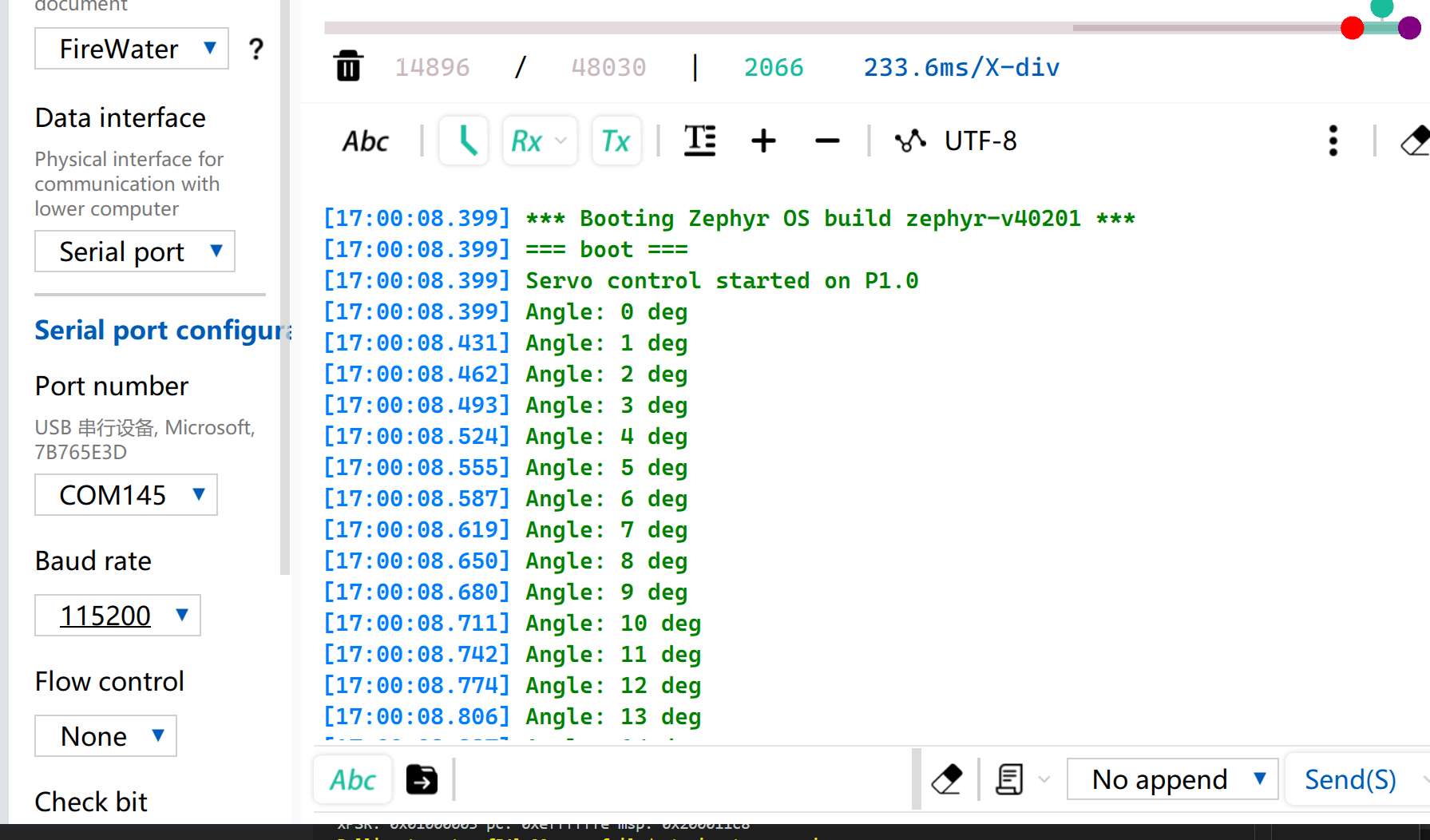
Result
After firmware flashing, the servo rotates from 0° to 180° at a speed of 33 radians per second and then rotates back to 0°.
Meanwhile, the current servo angle will be printed via USB serial port.
Analog
Analog I/O is based on an Analog-to-Digital Converter (ADC) and is primarily used to capture continuous analog voltage signals output by external sensors. After obtaining the raw digital sampling values (Raw Data), they can be mapped to actual engineering measurement values using specific linear or nonlinear conversion algorithms. This function is widely used in scenarios such as battery voltage sampling and real-time monitoring of physical quantities including soil moisture and ambient temperature.
Hardware Preparation
| Seeed Studio XIAO nRF54LM20A Sense | Seeed Studio Grove Base for XIAO | Grove - Capacitive Soil Moisture Sensor |
|---|---|---|
|  | |
Software Preparation
According to the pinout of XIAO nRF54LM20A, set P1.00 as the PWM output pin.
- For the pinout of the XIAO nRF54LM20A,click XIAO nRF54LM20A Pin List to view details.
- Modify the device tree file. Pin P1.00 corresponds to ADC channel 0 and needs to be bound to the device tree node.
/*
 * UART20 (console) + ADC channel 0 (P1.0 / AIN0) for XIAO nRF54LM20A.
 */

/ {
	chosen {
		zephyr,console    = &uart20;
		nordic,rpc-uart   = &uart20;
		zephyr,shell-uart = &uart20;
	};

	zephyr,user {
		io-channels = <&adc 0>;
	};
};


/* ── UART20 (console, TX: P1.11 / RX: P1.10) ── */
&uart20 {
	current-speed = <115200>;
	status = "okay";
};

&uart20_default {
	group1 {
		psels = <NRF_PSEL(UART_TX, 1, 11)>;
	};
	group2 {
		psels = <NRF_PSEL(UART_RX, 1, 10)>;
		bias-pull-up;
	};
};

&uart20_sleep {
	group1 {
		psels = <NRF_PSEL(UART_TX, 1, 11)>,
			<NRF_PSEL(UART_RX, 1, 10)>;
		low-power-enable;
	};
};
- Modify the
prj.conffile to enable ADC-related configurations.
CONFIG_ADC=y
CONFIG_ADC_NRFX_SAADC=y
CONFIG_SERIAL=y
CONFIG_PRINTK=y
CONFIG_UART_CONSOLE=y
- Write the main.c program, use the P1.00 pin as the analog input pin, and output the read value via the USB serial port every 500ms.
/*
 * Read ADC on P1.0 (AIN0, channel 0) and print raw value every 500 ms.
 */

#include <zephyr/kernel.h>
#include <zephyr/drivers/adc.h>
#include <zephyr/sys/printk.h>

static const struct adc_dt_spec adc_ch =
    ADC_DT_SPEC_GET(DT_PATH(zephyr_user));

int main(void)
{
    int ret;

    if (!adc_is_ready_dt(&adc_ch))
    {
        printk("ADC not ready\n");
        return -1;
    }

    ret = adc_channel_setup_dt(&adc_ch);
    if (ret < 0)
    {
        printk("ADC channel setup failed: %d\n", ret);
        return ret;
    }

    int16_t buf;
    struct adc_sequence seq = {
        .buffer = &buf,
        .buffer_size = sizeof(buf),
    };
    adc_sequence_init_dt(&adc_ch, &seq);

    while (1)
    {
        ret = adc_read_dt(&adc_ch, &seq);
        if (ret < 0)
        {
            printk("ADC read error: %d\n", ret);
        }
        else
        {
            printk("ADC raw: %d\n", buf);
        }
        k_msleep(500);
    }

    return 0;
}
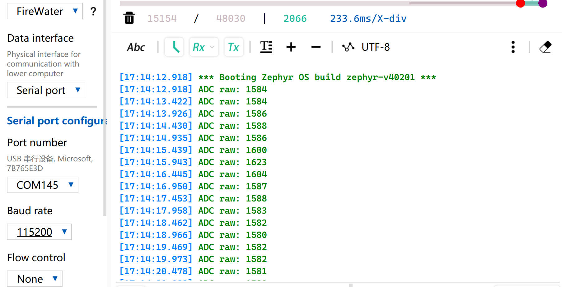
Result
After flashing the program, insert the Grove-Capacitive Soil Moisture Sensor into household potted plants.
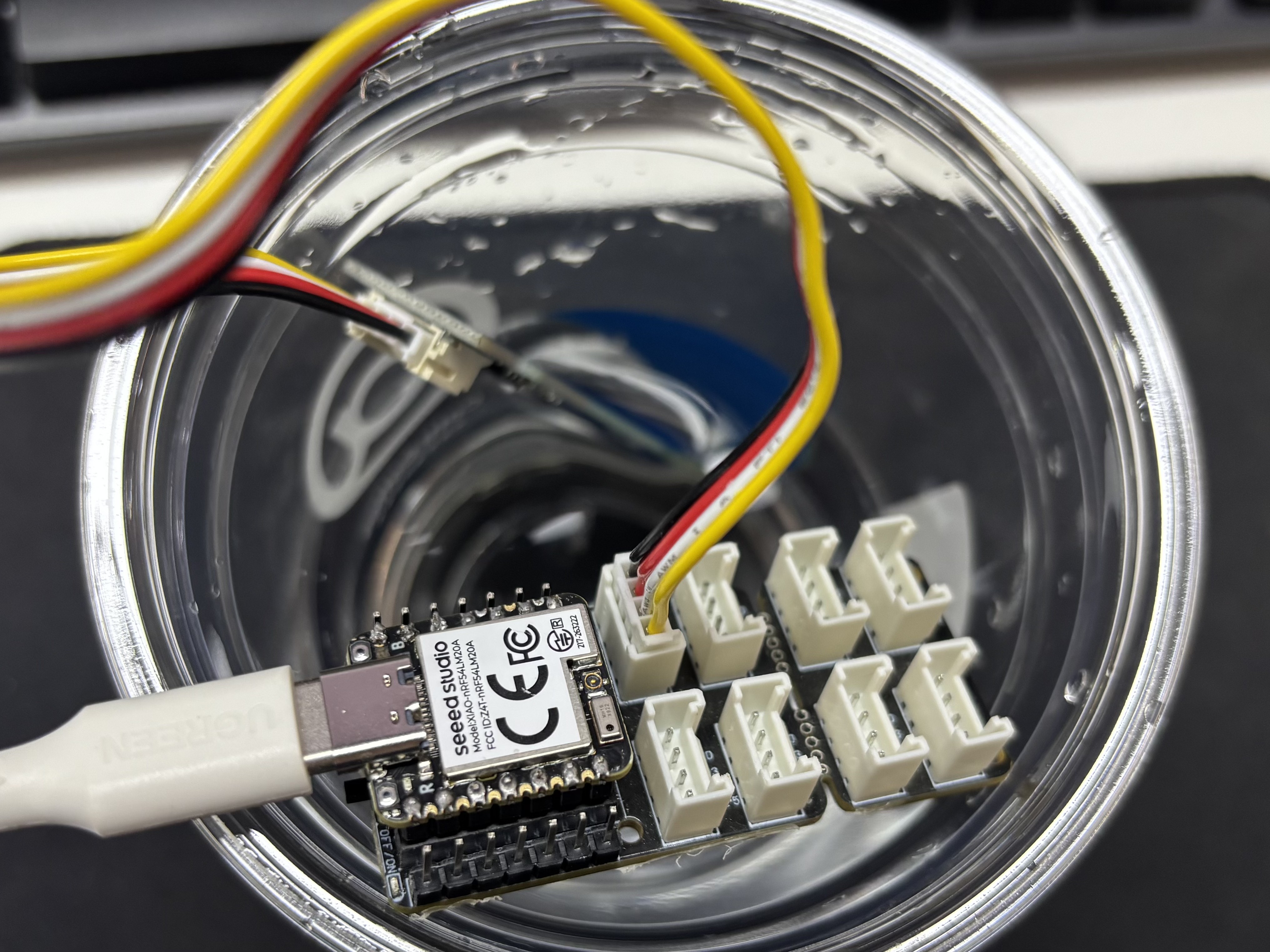
Open the serial port assistant on your computer and observe the output values.
Voltage Reference Reading Table
| Status | Sensor Output Voltage | Expected ADC Raw Value |
|---|---|---|
| In air (Dry) | ~2.0–2.4V | ~3400–4095 |
| In moist soil | ~1.3–1.8V | ~2200–3000 |
| Fully immersed in water | ~0.8–1.2V | ~1365–2048 |
Due to individual differences in components, different module measurements in the same environment may vary.
UART
Universal Asynchronous Receiver/Transmitter (UART) is a standard asynchronous serial communication protocol. It does not require external clock signals for synchronization, and realizes asynchronous data transmission and reception relying on the baud rate preset by both communication sides. In terms of physical wiring, a full-duplex data link can be established simply by cross-connecting the TX and RX pins of devices and connecting their grounds together. Featuring minimal hardware cost and support for simultaneous sending and receiving, UART is widely adopted in embedded systems for console log output, modular peripheral debugging and low-bandwidth point-to-point data communication.
Hardware Preparation
| Seeed Studio XIAO nRF54LM20A Sense | USB to TTL Converter |
|---|---|
 | |
Software Preparation
According to the pinout of XIAO nRF54LM20A, P1.08 and P1.09 can be selected as TX and RX pins for serial communication respectively.
- For the pinout of the XIAO nRF54LM20A,click XIAO nRF54LM20A Pin List to view details.
- Modify the device tree file, map pin P1.08 as UART TX and P1.09 as UART RX to the
uart21node, and set the serial port baud rate to 115200.
/*
 * UART21 Demo - Device Tree Overlay for XIAO nRF54LM20A
 * UART21: TX=P1.8, RX=P1.9
 *
 * Note: The pinctrl configuration is already defined in the board file.
 * This overlay enables UART21 and sets it as disabled for the default console
 * so it can be used as a general-purpose serial port.
 */

/* UART21 is already configured in the board dts, just make sure it's enabled */
&uart20 {
	current-speed = <115200>;
	status = "okay";
};

/* UART21 is already configured in the board dts, just make sure it's enabled */
&uart21 {
	current-speed = <115200>;
	status = "okay";
};
- Modify the
prj.confconfiguration file to enable relevant UART configurations.
# Serial and UART
CONFIG_SERIAL=y
# This demo uses uart_poll_in()/uart_poll_out().
# On nrfx UARTE, enabling async mode for the instance makes uart_poll_in()
# return -ENOTSUP, which breaks RX on uart21.

# Console (for logging via UART20)
CONFIG_CONSOLE=y
CONFIG_UART_CONSOLE=y

# Logging
CONFIG_LOG=y
CONFIG_LOG_BACKEND_UART=y
CONFIG_LOG_DEFAULT_LEVEL=3
- Write the main function. When the on-board BOOT button is pressed, the serial port status and pin configuration will be printed to the computer via the serial port; otherwise, the running status will be printed by default.
main.c
/*
 * UART21 Demo for XIAO nRF54LM20A (Polling Mode)
 *
 * This demo shows how to use UART21 for serial communication using polling mode.
 * - TX: P1.08
 * - RX: P1.09
 * - Baud rate: 115200
 *
 * The demo will:
 * 1. Send a welcome message on startup
 * 2. Echo back any received characters
 * 3. Periodically send a heartbeat message
 */

#include <zephyr/kernel.h>
#include <zephyr/device.h>
#include <zephyr/drivers/uart.h>
#include <zephyr/logging/log.h>
#include <stdio.h>
#include <string.h>

LOG_MODULE_REGISTER(uart21_demo, LOG_LEVEL_INF);

/* UART21 device */
static const struct device *uart21_dev = DEVICE_DT_GET(DT_NODELABEL(uart21));

#define RX_BUF_SIZE 128
#define TX_BUF_SIZE 256
#define HEARTBEAT_INTERVAL_MS 5000

static uint8_t rx_buf[RX_BUF_SIZE];
static size_t rx_buf_pos = 0;
static char tx_buf[TX_BUF_SIZE];

/* Send a string over UART21 using polling */
static void uart21_send_string(const char *str)
{
	while (*str)
	{
		uart_poll_out(uart21_dev, *str++);
	}
}

/* Receive a character from UART21 (non-blocking) */
static int uart21_recv_char(uint8_t *c)
{
	return uart_poll_in(uart21_dev, c);
}

static void handle_complete_line(void)
{
	rx_buf[rx_buf_pos] = '\0';

	if (rx_buf_pos > 0)
	{
		LOG_INF("Received: %s", rx_buf);
		uart21_send_string("\r\nYou sent: ");
		uart21_send_string((const char *)rx_buf);
	}

	uart21_send_string("\r\n");
	rx_buf_pos = 0;
	memset(rx_buf, 0, sizeof(rx_buf));
}

/* Process a received byte and maintain a simple line buffer */
static void process_rx_byte(uint8_t c)
{
	static bool last_was_cr;

	if (c == '\r' || c == '\n')
	{
		if (c == '\n' && last_was_cr)
		{
			last_was_cr = false;
			return;
		}

		uart21_send_string("\r\n");
		handle_complete_line();
		last_was_cr = (c == '\r');
		return;
	}

	last_was_cr = false;
	uart_poll_out(uart21_dev, c);

	if (rx_buf_pos < RX_BUF_SIZE - 1)
	{
		rx_buf[rx_buf_pos++] = c;
		return;
	}

	uart21_send_string("\r\n[Warning] Input too long, buffer cleared.\r\n");
	rx_buf_pos = 0;
	memset(rx_buf, 0, sizeof(rx_buf));
}

int main(void)
{
	uint8_t c;
	uint32_t heartbeat_count = 0;
	int64_t last_heartbeat = 0;

	LOG_INF("========================================");
	LOG_INF("  UART21 Demo for XIAO nRF54LM20A");
	LOG_INF("========================================");
	LOG_INF("");

	/* Check if UART21 device is ready */
	if (!device_is_ready(uart21_dev))
	{
		LOG_ERR("UART21 device not ready!");
		return -1;
	}
	LOG_INF("UART21 device ready: %s", uart21_dev->name);

	/* Send welcome message */
	uart21_send_string("\r\n");
	uart21_send_string("========================================\r\n");
	uart21_send_string("  UART21 Demo for XIAO nRF54LM20A\r\n");
	uart21_send_string("========================================\r\n");
	uart21_send_string("\r\n");
	uart21_send_string("Pin Configuration:\r\n");
	uart21_send_string("  TX: P1.08\r\n");
	uart21_send_string("  RX: P1.09\r\n");
	uart21_send_string("  Baud Rate: 115200\r\n");
	uart21_send_string("\r\n");
	uart21_send_string("Type something and press Enter to see it echoed.\r\n");
	uart21_send_string("\r\n");

	LOG_INF("UART21 demo started. Waiting for data...");
	LOG_INF("Connect UART terminal to P1.8(TX) and P1.9(RX)");

	last_heartbeat = k_uptime_get();

	/* Main loop */
	while (1)
	{
		/* Check for received data */
		if (uart21_recv_char(&c) == 0)
		{
			process_rx_byte(c);
		}

		/* Check for heartbeat */
		int64_t now = k_uptime_get();
		if (now - last_heartbeat >= HEARTBEAT_INTERVAL_MS)
		{
			last_heartbeat = now;
			heartbeat_count++;

			snprintf(tx_buf, sizeof(tx_buf),
					 "\r\n[Heartbeat #%u] UART21 running...\r\n",
					 heartbeat_count);
			uart21_send_string(tx_buf);

			LOG_INF("Heartbeat #%u sent", heartbeat_count);
		}

		/* Small delay to prevent busy loop */
		k_msleep(10);
	}

	return 0;
}
Result
- Wire according to the table order
| XIAO nRF54LM20A | CH340 |
|---|---|
| VBUS | 5V |
| GND | GND |
| P1.08 - TX | RX |
| P1.09 - RX | TX |
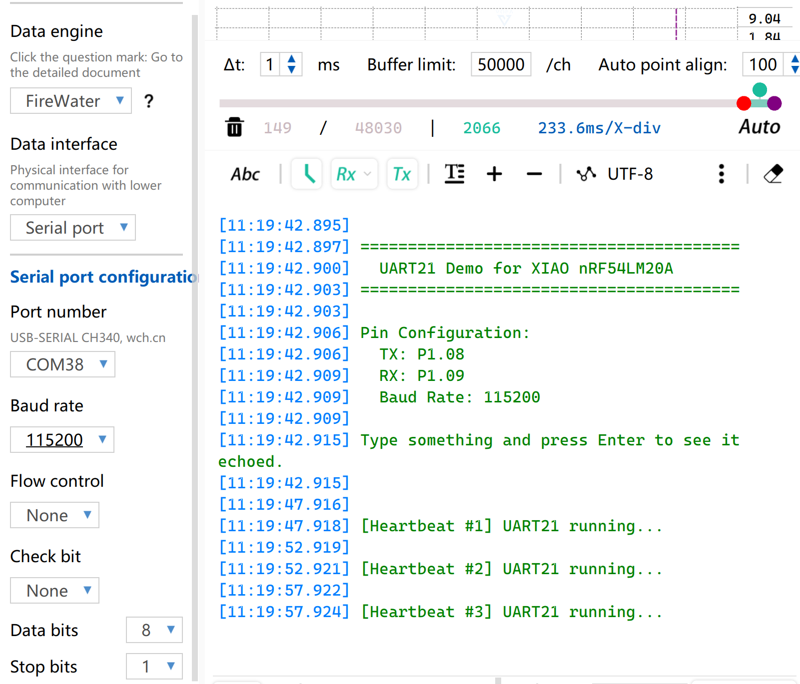
- Open the serial port monitoring software on your computer. When the on-board BOOT button is pressed, the configured serial port information will be printed via the serial port. By default, the string
[Heartbeat # number] UART21 running...will be printed.
I2C
I2C is a synchronous, half-duplex data communication protocol. It enables multi-device connection through addressing via the SCL clock line and SDA data line, and is commonly used to read data from sensors requiring relatively high transmission rates, such as IMUs and temperature/humidity sensors, or for OLED display output.
Hardware Preparation
| Seeed Studio XIAO nRF54LM20A Sense | Seeed Studio Expansion Board Base for XIAO |
|---|---|
 | |
Software Preparation
According to the pinout of XIAO nRF54LM20A, P1.03 and P1.07 can be configured as I2C pins.
- For the pinout of the XIAO nRF54LM20A,click XIAO nRF54LM20A Pin List to view details.
- Modify the device tree, configure P1.03 and P1.07 on XIAO nRF54LM20A as the pins of the
i2c22device tree node respectively, then add the device tree node for the display. The OLED display features a resolution of 128×64 and adopts the common SSD1306 driver chip.
/ {
        chosen {
                zephyr,display = &ssd1306_128x64;
        };
};

&i2c22 {
        status = "okay";
        zephyr,concat-buf-size = <2048>;
        ssd1306_128x64: ssd1306@3c {
                compatible = "solomon,ssd1306fb";
                reg = <0x3c>;
                width = <128>;
                height = <64>;
                segment-offset = <0>;
                page-offset = <0>;
                display-offset = <0>;
                multiplex-ratio = <63>;
                segment-remap;
                com-invdir;
                prechargep = <0x22>;
        };
};
- Modify the
prj.conffile to enable I2C and display-related configurations.
CONFIG_STDOUT_CONSOLE=y
CONFIG_HEAP_MEM_POOL_SIZE=16384
CONFIG_I2C=y
CONFIG_DISPLAY=y
CONFIG_SSD1306=y
CONFIG_LOG=y
CONFIG_LOG_DEFAULT_LEVEL=4
CONFIG_CHARACTER_FRAMEBUFFER=y
- Write the main function to set the display position and functions for the string.
main.c
#include <zephyr/kernel.h>
#include <zephyr/device.h>
#include <zephyr/display/cfb.h>
#include <stdio.h>
#include <string.h>
#define LOG_LEVEL CONFIG_LOG_DEFAULT_LEVEL
#include <zephyr/logging/log.h>
LOG_MODULE_REGISTER(main_app, LOG_LEVEL);
#define CFB_MAX_FONT_INDEX 42
/* Display content */
#define LINE1_TEXT "Hello XIAO"
#define LINE2_TEXT "nRF54LM20A"
#define TOTAL_LINES 2
static int display_init(const struct device **dev) {
*dev = DEVICE_DT_GET(DT_CHOSEN(zephyr_display));
if (!device_is_ready(*dev)) {
LOG_ERR("Device %s not ready", (*dev)->name);
return -1;
}
if (display_set_pixel_format(*dev, PIXEL_FORMAT_MONO10) != 0) {
if (display_set_pixel_format(*dev, PIXEL_FORMAT_MONO01) != 0) {
LOG_ERR("Failed to set required pixel format");
return -1;
}
}
LOG_INF("Initialized %s", (*dev)->name);
return 0;
}
static int framebuffer_setup(const struct device *dev) {
if (cfb_framebuffer_init(dev)) {
LOG_ERR("Framebuffer initialization failed!");
return -1;
}
cfb_framebuffer_clear(dev, false);
display_blanking_off(dev);
return 0;
}
static int select_font(const struct device *dev, uint8_t *font_width, uint8_t *font_height) {
int chosen_font_idx = -1;
uint8_t current_font_width, current_font_height;
for (int idx = 0; idx < CFB_MAX_FONT_INDEX; idx++) {
if (cfb_get_font_size(dev, idx, ¤t_font_width, ¤t_font_height) != 0) {
continue;
}
if (current_font_width == 0 || current_font_height == 0) {
continue;
}
if (current_font_width == 8 && current_font_height == 8) {
chosen_font_idx = idx;
*font_width = current_font_width;
*font_height = current_font_height;
cfb_framebuffer_set_font(dev, chosen_font_idx);
LOG_INF("Selected 8x8 font idx: %d", chosen_font_idx);
break;
}
if (chosen_font_idx == -1) {
chosen_font_idx = idx;
*font_width = current_font_width;
*font_height = current_font_height;
cfb_framebuffer_set_font(dev, chosen_font_idx);
LOG_INF("Fallback font idx: %d, size: %dx%d",
chosen_font_idx, *font_width, *font_height);
}
}
if (chosen_font_idx == -1) {
LOG_ERR("No suitable font found!");
return -1;
}
return 0;
}
/**
* @brief Print a line of text centered on the display
* @param dev Display device
* @param text String to be printed
* @param line_index Index of current line (0-indexed)
* @param total_lines Total number of lines (for vertical centering calculation)
* @param font_width Font width in pixels
* @param font_height Font height in pixels
* @param x_res Horizontal resolution of the display
* @param y_res Vertical resolution of the display
*/
static void print_text_centered(const struct device *dev,
const char *text,
int line_index,
int total_lines,
uint8_t font_width,
uint8_t font_height,
uint16_t x_res,
uint16_t y_res)
{
int text_len = (int)strlen(text);
/* Horizontal center: (screen width - total text pixel width) / 2 */
int pixel_x = (x_res - text_len * font_width) / 2;
/* Vertical center: calculate total block height first, then offset current line */
int block_height = total_lines * font_height;
int pixel_y = (y_res - block_height) / 2 + line_index * font_height;
/* Prevent coordinate out-of-bounds */
if (pixel_x < 0) pixel_x = 0;
if (pixel_y < 0) pixel_y = 0;
if (cfb_print(dev, text, pixel_x, pixel_y)) {
LOG_ERR("Failed to print \"%s\" at (%d, %d)", text, pixel_x, pixel_y);
}
LOG_DBG("Print \"%s\" at pixel (%d, %d)", text, pixel_x, pixel_y);
}
int main(void) {
const struct device *dev;
uint8_t font_width = 0;
uint8_t font_height = 0;
if (display_init(&dev) != 0) return 0;
if (framebuffer_setup(dev) != 0) return 0;
if (select_font(dev, &font_width, &font_height) != 0) return 0;
uint16_t x_res = cfb_get_display_parameter(dev, CFB_DISPLAY_WIDTH);
uint16_t y_res = cfb_get_display_parameter(dev, CFB_DISPLAY_HEIGHT);
LOG_INF("Display resolution: %dx%d", x_res, y_res);
cfb_set_kerning(dev, 0);
while (1) {
cfb_framebuffer_clear(dev, false);
print_text_centered(dev, LINE1_TEXT, 0, TOTAL_LINES,
font_width, font_height, x_res, y_res);
print_text_centered(dev, LINE2_TEXT, 1, TOTAL_LINES,
font_width, font_height, x_res, y_res);
cfb_framebuffer_finalize(dev);
k_sleep(K_MSEC(1000));
}
return 0;
}
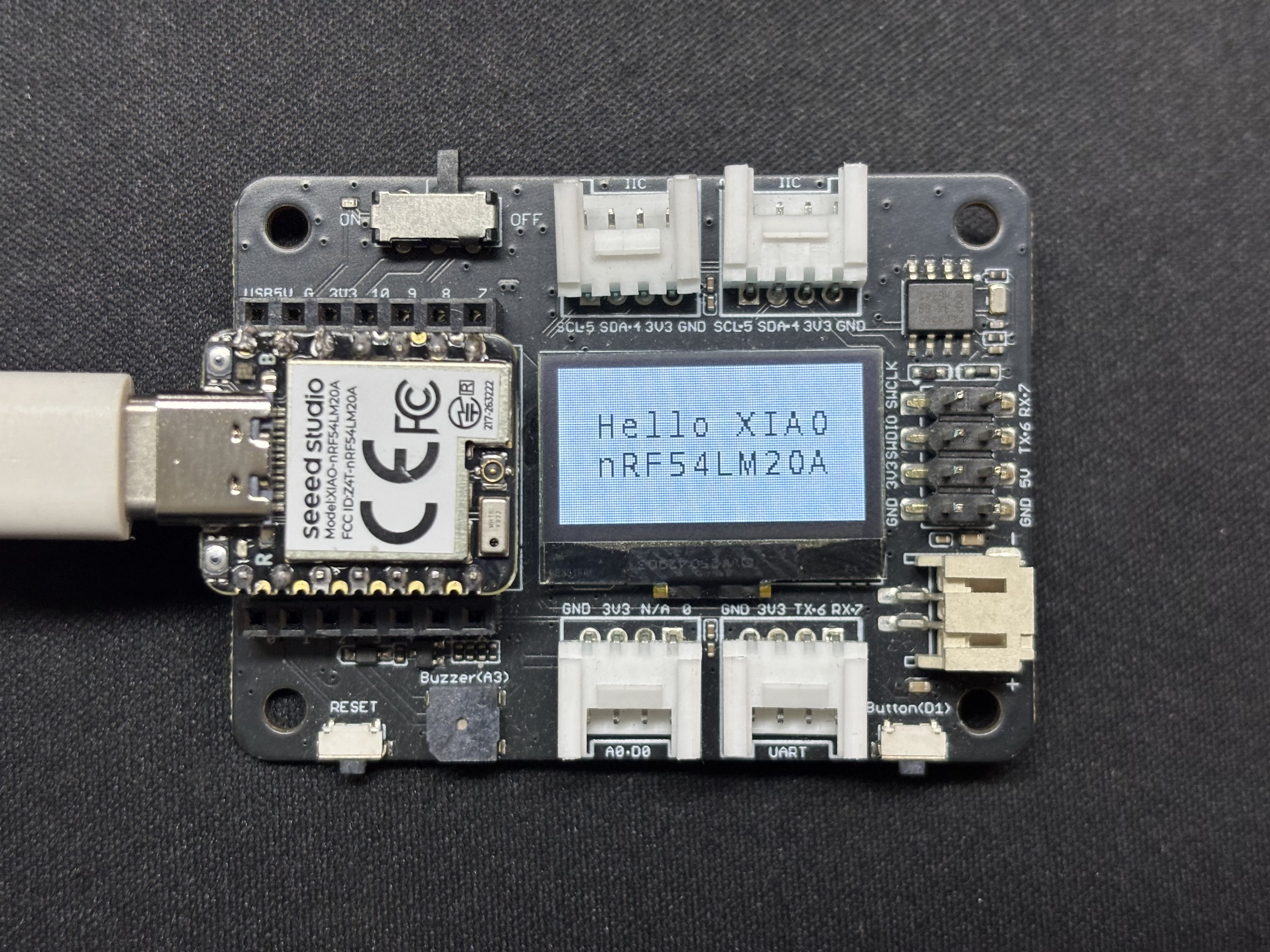
Result
After the program runs, the text Hello XIAO nRF54LM20A will be displayed on the screen, and thread data will be printed through the USB serial port.
SPI
SPI is a high-speed, synchronous and full-duplex communication protocol. Unlike asynchronous communication, SPI relies on a dedicated SCLK clock line for precise data synchronization. It generally adopts the classic four-wire hardware topology consisting of MOSI, MISO and chip select CS/SS pins. Equipped with independent data sending and receiving channels and high bus clock frequency, SPI delivers excellent data throughput. It is widely used in peripheral driving scenarios demanding high bandwidth, such as mass storage devices including Flash and SD cards, high-resolution and high-refresh-rate screen displays, and high-frequency sampling sensors.
Hardware Preparation
| Seeed Studio XIAO nRF54LM20A Sense | Round Display for Seeed Studio XIAO |
|---|---|
 | |
Software Preparation
- For the pinout of the XIAO nRF54LM20A,click XIAO nRF54LM20A Pin List to view details.
- Modify the device tree file. To drive the LCD screen, enable the spi23 node and configure pin mappings in the device tree. Set P1.04, P1.05 and P1.06 as SPI SCK, MISO and MOSI respectively. Meanwhile, configure P1.31 and P1.29 as the screen CS (Chip Select) and DC (Data/Command) control pins.
app.overlay
#include <dt-bindings/pinctrl/nrf-pinctrl.h>
#include <zephyr/dt-bindings/gpio/gpio.h>
#include <zephyr/dt-bindings/display/panel.h>

/*
 * GC9X01X 240x240 round LCD configuration for XIAO nRF54LM20A
 * SPI23:  SCK=P1.04  MOSI=P1.06  MISO=P1.05
 * CS:     P1.31  (SPI bus software CS)
 * DC:     P1.29  (Data/Command select, on MIPI DBI node)
 *
 * In Zephyr 4.x the GC9X01X driver uses the MIPI DBI interface.
 * The display node must be a child of a zephyr,mipi-dbi-spi node,
 * which references the SPI controller via spi-dev phandle.
 */

/ {
    chosen {
        zephyr,console    = &uart20;
        nordic,rpc-uart   = &uart20;
        zephyr,shell-uart = &uart20;
        zephyr,display    = &gc9x01x;
    };

    mipi_dbi {
        compatible = "zephyr,mipi-dbi-spi";
        spi-dev = <&spi23>;
        dc-gpios = <&gpio1 29 GPIO_ACTIVE_HIGH>;
        write-only;
        #address-cells = <1>;
        #size-cells = <0>;

        gc9x01x: gc9x01x@0 {
            compatible = "galaxycore,gc9x01x";
            reg = <0>;
            mipi-max-frequency = <40000000>;
            pixel-format = <PANEL_PIXEL_FORMAT_RGB_565>;
            display-inversion;
            width  = <240>;
            height = <240>;
            status = "okay";
        };
    };
};

&spi23 {
    compatible = "nordic,nrf-spim";
    pinctrl-names = "default", "sleep";
    pinctrl-0 = <&spi23_default>;
    pinctrl-1 = <&spi23_sleep>;
    status = "okay";

    /* CS P1.31 — index 0 used by the MIPI DBI driver */
    cs-gpios = <&gpio1 31 GPIO_ACTIVE_LOW>;
};

&uart20 {
    status = "okay";
};

&pinctrl {
    spi23_default: spi23_default {
        group1 {
            psels = <NRF_PSEL(SPIM_SCK,  1, 4)>,
                    <NRF_PSEL(SPIM_MOSI, 1, 6)>;
        };
        group2 {
            psels = <NRF_PSEL(SPIM_MISO, 1, 5)>;
            bias-pull-up;
        };
    };

    spi23_sleep: spi23_sleep {
        group1 {
            psels = <NRF_PSEL(SPIM_SCK,  1, 4)>,
                    <NRF_PSEL(SPIM_MOSI, 1, 6)>,
                    <NRF_PSEL(SPIM_MISO, 1, 5)>;
            low-power-enable;
        };
    };
};

&uart20_default {
    /delete-node/ group1;
    /delete-node/ group2;

    group1 {
        psels = <NRF_PSEL(UART_TX, 1, 11)>;
    };
    group2 {
        psels = <NRF_PSEL(UART_RX, 1, 10)>;
        bias-pull-up;
    };
};

&uart20_sleep {
    /delete-node/ group1;

    group1 {
        psels = <NRF_PSEL(UART_TX, 1, 11)>,
                <NRF_PSEL(UART_RX, 1, 10)>;
        low-power-enable;
    };
};
- Modify prj.conf to enable SPI-related configurations.
CONFIG_LOG=y
CONFIG_LOG_DEFAULT_LEVEL=3
CONFIG_CONSOLE=y
CONFIG_UART_CONSOLE=y
CONFIG_GPIO=y
CONFIG_SPI=y
CONFIG_DISPLAY=y
CONFIG_CHARACTER_FRAMEBUFFER=y
CONFIG_CHARACTER_FRAMEBUFFER_USE_DEFAULT_FONTS=y
CONFIG_HEAP_MEM_POOL_SIZE=32768
CONFIG_MAIN_STACK_SIZE=4096
- Modify the main.c program and write the solid-color screen filling logic.
main.c
#include <zephyr/kernel.h>
#include <zephyr/device.h>
#include <zephyr/display/cfb.h>
#include <zephyr/drivers/display.h>
#include <string.h>
#include <stdlib.h>

#define LOG_LEVEL CONFIG_LOG_DEFAULT_LEVEL
#include <zephyr/logging/log.h>
LOG_MODULE_REGISTER(gc9a01_demo, LOG_LEVEL);

/* GC9A01 Resolution */
#define LCD_W  240
#define LCD_H  240

/* RGB565 Color Definitions */
#define COLOR_BLACK   0x0000U
#define COLOR_WHITE   0xFFFFU
#define COLOR_RED     0xF800U
#define COLOR_GREEN   0x07E0U
#define COLOR_BLUE    0x001FU
#define COLOR_YELLOW  0xFFE0U
#define COLOR_CYAN    0x07FFU
#define COLOR_MAGENTA 0xF81FU
#define COLOR_ORANGE  0xFD20U

/* -------------------------------------------------------
 * Low-level: Fill entire screen using display_write
 * buf: RGB565 pixel buffer, length = w * h * 2 bytes
 * ------------------------------------------------------- */
static uint16_t fb[LCD_W * LCD_H];   /* ~115 KB, declared globally to avoid stack overflow */

static void fill_screen(const struct device *dev, uint16_t color)
{
    /* RGB565 Big-endian (Default for GC9A01) */
    uint16_t be = (color >> 8) | (color << 8);
    for (int i = 0; i < LCD_W * LCD_H; i++) {
        fb[i] = be;
    }

    struct display_buffer_descriptor desc = {
        .buf_size = sizeof(fb),
        .width    = LCD_W,
        .height   = LCD_H,
        .pitch    = LCD_W,
    };
    display_write(dev, 0, 0, &desc, fb);
}

/* -------------------------------------------------------
 * Scene 1: Solid color full-screen fill, cycle colors
 * ------------------------------------------------------- */
static void demo_solid_colors(const struct device *dev)
{
    static const uint16_t colors[] = {
        COLOR_RED, COLOR_GREEN, COLOR_BLUE,
        COLOR_YELLOW, COLOR_CYAN, COLOR_MAGENTA,
    };
    static const char *names[] = {
        "RED", "GREEN", "BLUE", "YELLOW", "CYAN", "MAGENTA",
    };

    for (int i = 0; i < ARRAY_SIZE(colors); i++) {
        LOG_INF("Solid: %s", names[i]);
        fill_screen(dev, colors[i]);
        k_sleep(K_MSEC(600));
    }
}

/* -------------------------------------------------------
 * Scene 2: Color vertical bars (6 bars, 40px width each)
 * ------------------------------------------------------- */
static void demo_color_bars(const struct device *dev)
{
    static const uint16_t bar_colors[] = {
        COLOR_RED, COLOR_ORANGE, COLOR_YELLOW,
        COLOR_GREEN, COLOR_BLUE, COLOR_MAGENTA,
    };
    static const int BAR_W = LCD_W / ARRAY_SIZE(bar_colors);  /* = 40 */

    for (int y = 0; y < LCD_H; y++) {
        for (int x = 0; x < LCD_W; x++) {
            uint16_t c = bar_colors[x / BAR_W];
            uint16_t be = (c >> 8) | (c << 8);
            fb[y * LCD_W + x] = be;
        }
    }

    struct display_buffer_descriptor desc = {
        .buf_size = sizeof(fb),
        .width    = LCD_W,
        .height   = LCD_H,
        .pitch    = LCD_W,
    };
    display_write(dev, 0, 0, &desc, fb);
    LOG_INF("Color bars");
    k_sleep(K_MSEC(2000));
}

/* -------------------------------------------------------
 * Main Application
 * ------------------------------------------------------- */
int main(void)
{
    LOG_INF("GC9A01 demo — XIAO nRF54LM20A");

    const struct device *dev = DEVICE_DT_GET(DT_CHOSEN(zephyr_display));
    if (!device_is_ready(dev)) {
        LOG_ERR("Display device not ready");
        return 0;
    }

    /* Set pixel format: GC9A01 uses RGB565 */
    if (display_set_pixel_format(dev, PIXEL_FORMAT_RGB_565) != 0) {
        LOG_ERR("Failed to set pixel format");
        return 0;
    }

    display_blanking_off(dev);
    LOG_INF("Display ready, starting demo loop");

    while (1) {
        demo_solid_colors(dev);   /* 6-color cycle ~3.6s */
        demo_color_bars(dev);     /* Color vertical bars ~2s */
    }

    return 0;
}
Result
After power-on, the program refreshes the screen in the sequence of red, orange, yellow, green, cyan, blue and purple, and finally displays colorful striped patterns.
Tech Support & Product Discussion
Thank you for choosing our products! We are here to provide you with different support to ensure that your experience with our products is as smooth as possible. We offer several communication channels to cater to different preferences and needs.