Seeed Studio XIAO nRF54LM20A Sense with Arduino
This section walks you through the required hardware and software preparation for Arduino development. By following the steps below, you will set up your development environment, configure the Arduino IDE, and prepare your XIAO board for programming. Once the setup is complete, you can quickly build, upload, and test the provided example sketches.
Getting Started
Hardware Preparation
You need to prepare the following:
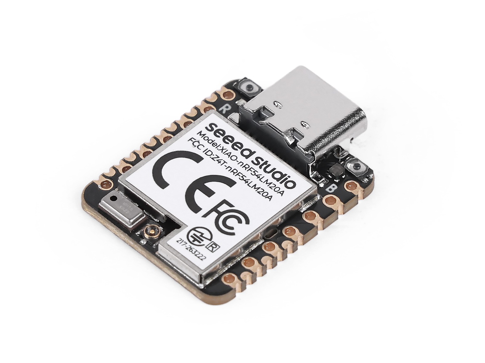
- 1 x Seeed Studio XIAO nRF54LM20A Sense
- 1 x Computer
- 1 x USB Type-C cable
| Seeed Studio XIAO nRF54LM20A Sense |
|---|
 |
Software
The XIAO nRF54LM20A supports development with the Arduino IDE. Before getting started, please install and configure the Arduino IDE.
If this is your first time using Arduino, we highly recommend you to refer to Getting Started with Arduino.
-
Step 1. Download and install the stable version of Arduino IDE according to your operating system.
-
Step 2. Launch the Arduino application.
-
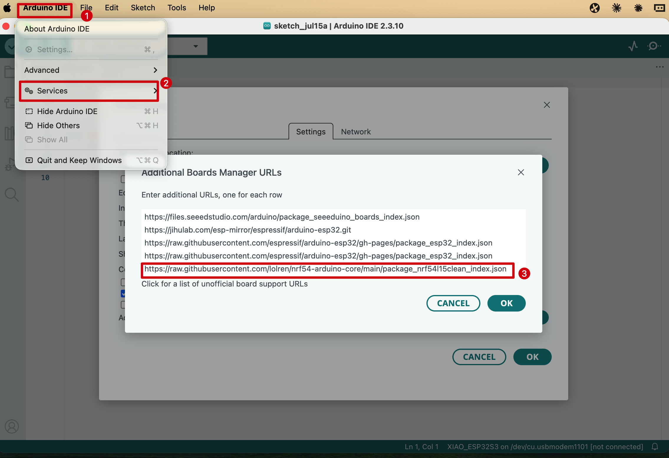
Step 3. Open Arduino IDE > Settings, find Additional Boards Manager URLs, and add the following URL:
https://raw.githubusercontent.com/lolren/nrf54-arduino-core/main/package_nrf54l15clean_index.json
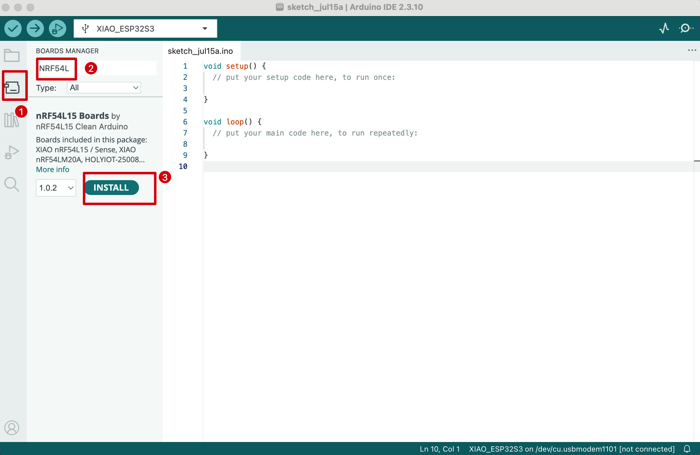
- Step 4. Go to Tools > Board > Boards Manager, search for nRF54L15 Boards, and install it.
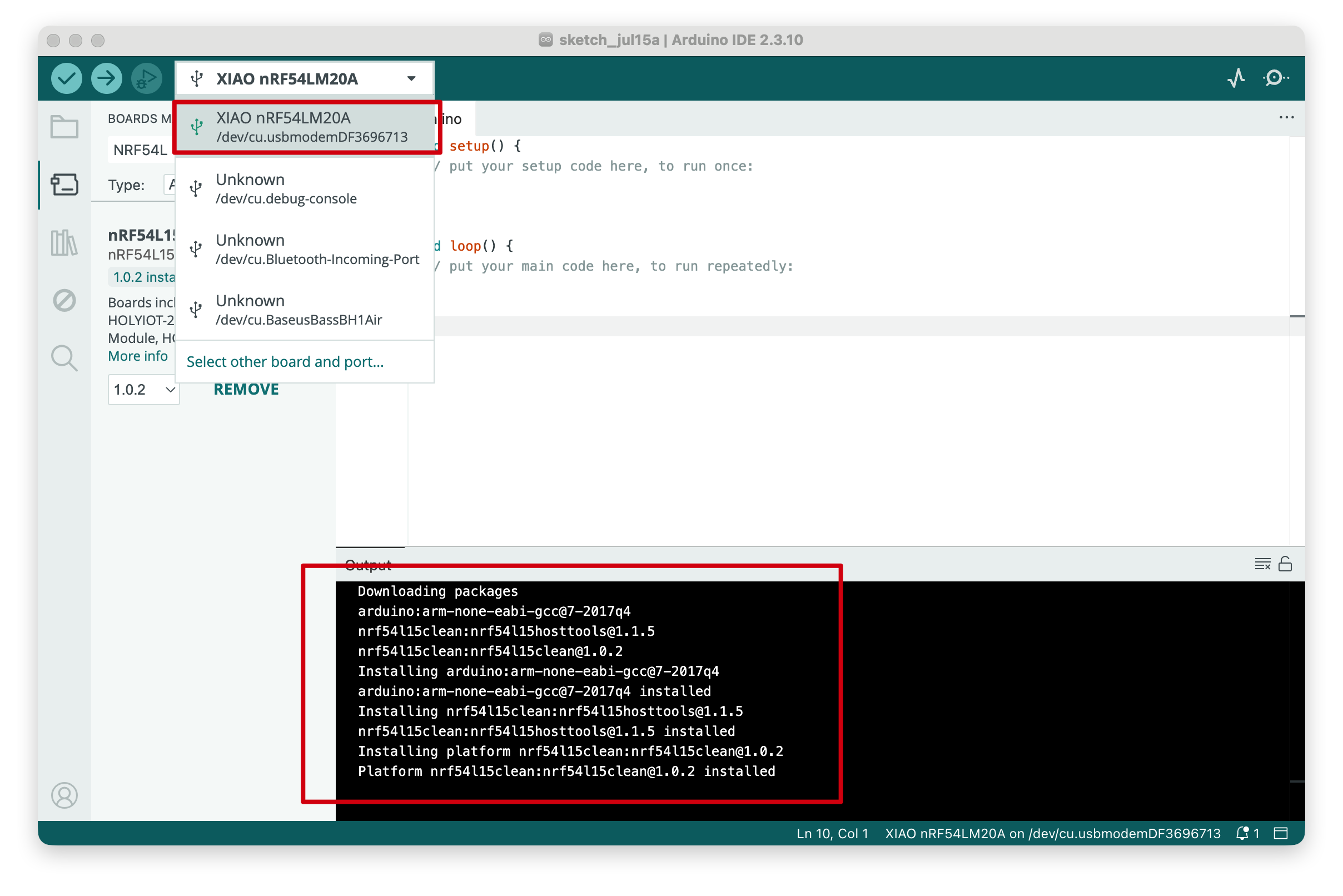
- Step 5. After connecting the board, select the following board in the Arduino IDE:
Tools > Board > nRF54L15 Boards > XIAO nRF54LM20A
Upload Program
The following example uses a simple blink program.
Step 1. Select the Blink example code for testing.
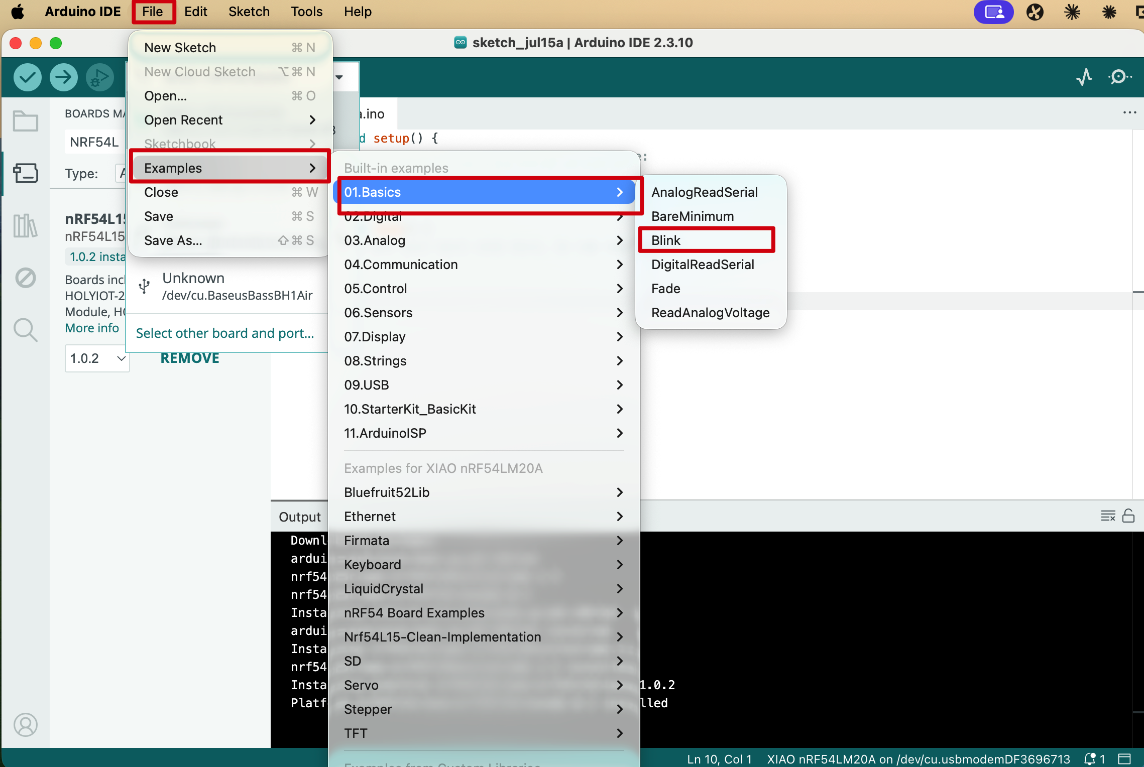
Step 2. Click Upload to compile and upload the sketch.

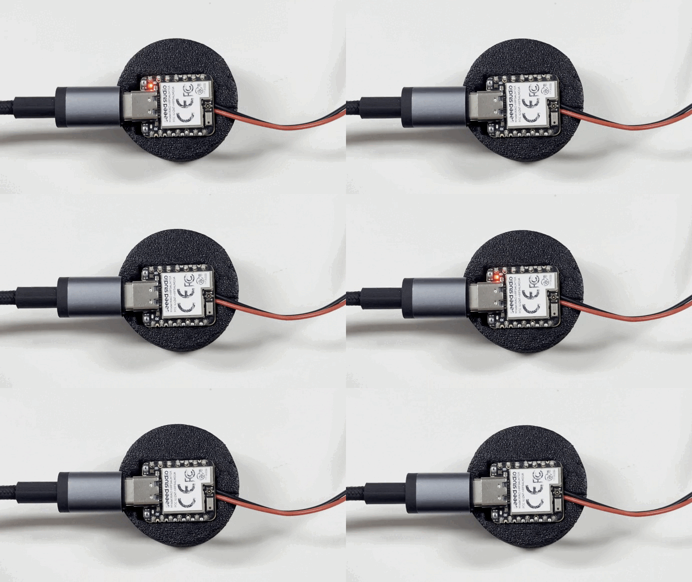
Effect demonstration:
After you upload the program and press the reset button, the L indicator will flash at 1-second intervals.
Digital
Digital pins are commonly used to control external sensors and actuators by switching between high and low logic levels. This section uses a Grove Button and a Grove Buzzer with the Grove Base for XIAO to demonstrate basic digital input and output on the XIAO nRF54LM20A.
Hardware Preparation
| Seeed Studio XIAO nRF54LM20A Sense | Seeed Studio Grove Base for XIAO | Grove - Piezo Buzzer | Grove - Button |
|---|---|---|---|
|  |  |  |
Software Preparation
According to the pinout of the XIAO nRF54LM20A, D0 / P1.00 can be used for the Grove Button, and D1 / P1.31 can be used for the Grove Buzzer.
- For the pinout of the XIAO nRF54LM20A, click XIAO nRF54LM20A Pin List to view details.
Create a new Arduino sketch and upload the following code.
#define BUTTON_PIN 0
#define BUZZER_PIN 1

int last_val = LOW;

void setup() {
  Serial.begin(115200);
  while (!Serial) {
    delay(10);
  }

  Serial.println("=== Grove Button + Buzzer (Digital Mode) ===");

  pinMode(BUTTON_PIN, INPUT);

  pinMode(BUZZER_PIN, OUTPUT);
  digitalWrite(BUZZER_PIN, LOW);

  Serial.println("Button:  D0 (input)");
  Serial.println("Buzzer:  D1 (output)");
  Serial.println("Press the button to turn on the buzzer...");
}

void loop() {
  int val = digitalRead(BUTTON_PIN);

  digitalWrite(BUZZER_PIN, val);

  if (val != last_val) {
    Serial.print("Button ");
    Serial.print(val ? "PRESSED " : "released");
    Serial.print(" -> Buzzer ");
    Serial.println(val ? "ON" : "OFF");

    last_val = val;
  }

  delay(10);
}
Result
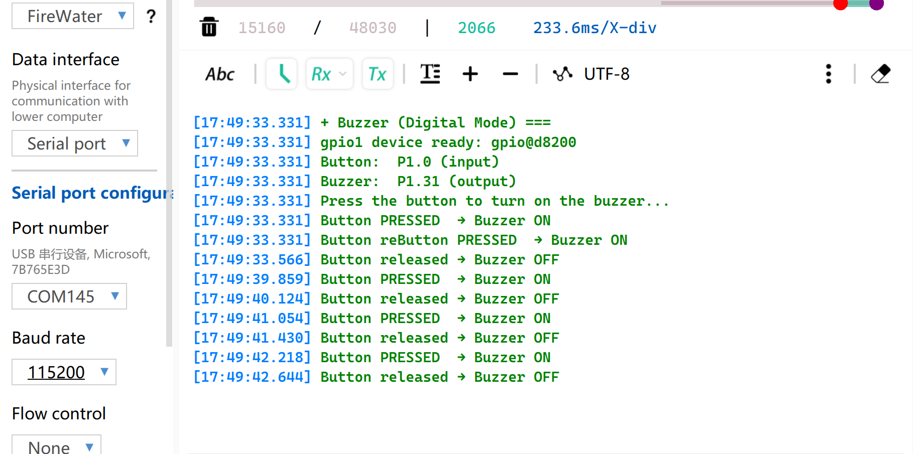
After uploading the sketch, press the button. The buzzer will beep, and the Serial Monitor will print the button and buzzer status.
Set the Serial Monitor baud rate to 115200.
PWM
PWM outputs a timed digital waveform at a fixed frequency and changes the duty cycle to approximate an analog control signal. It is commonly used for servo angle control, LED brightness adjustment, motor speed control, and other applications that need smooth output control.
Hardware Preparation
| Seeed Studio XIAO nRF54LM20A Sense | Seeed Studio Grove Base for XIAO | Grove - Servo |
|---|---|---|
| |  |
Software Preparation
According to the pinout of the XIAO nRF54LM20A, D0 / P1.00 can be used as the PWM control pin for the Grove Servo.
- For the pinout of the XIAO nRF54LM20A, click XIAO nRF54LM20A Pin List to view details.
Create a new Arduino sketch to implement PWM servo control and configure parameters such as the PWM period.
#include <Arduino.h>

#define SERVO_PIN PIN_D0

#define SERVO_FREQ_HZ      50
#define SERVO_PERIOD_US    20000
#define SERVO_MIN_US       500
#define SERVO_MAX_US       2500

#define STEP_FWD_MS        30
#define STEP_RET_MS        30

#define PWM_RESOLUTION     16
#define PWM_MAX_VALUE      65535UL

static void set_angle(int degrees)
{
  if (degrees < 0) degrees = 0;
  if (degrees > 180) degrees = 180;

  uint32_t pulse_us = SERVO_MIN_US +
                      (uint32_t)((uint64_t)degrees *
                                 (SERVO_MAX_US - SERVO_MIN_US) / 180UL);

  uint32_t duty = (uint32_t)((uint64_t)pulse_us *
                             PWM_MAX_VALUE / SERVO_PERIOD_US);

  analogWrite(SERVO_PIN, duty);
}

void setup()
{
  Serial.begin(115200);
  delay(1000);

  Serial.println("=== boot ===");
  Serial.println("Servo control started on P1.0 / PIN_D0");

  pinMode(SERVO_PIN, OUTPUT);

  analogWriteResolution(PWM_RESOLUTION);
  analogWritePinFrequency(SERVO_PIN, SERVO_FREQ_HZ);

  set_angle(0);
  delay(500);
}

void loop()
{
  for (int a = 0; a <= 180; a++) {
    set_angle(a);

    Serial.print("Angle: ");
    Serial.print(a);
    Serial.println(" deg");

    delay(STEP_FWD_MS);
  }

  for (int a = 180; a >= 0; a--) {
    set_angle(a);

    Serial.print("Angle: ");
    Serial.print(a);
    Serial.println(" deg");

    delay(STEP_RET_MS);
  }
}
Result
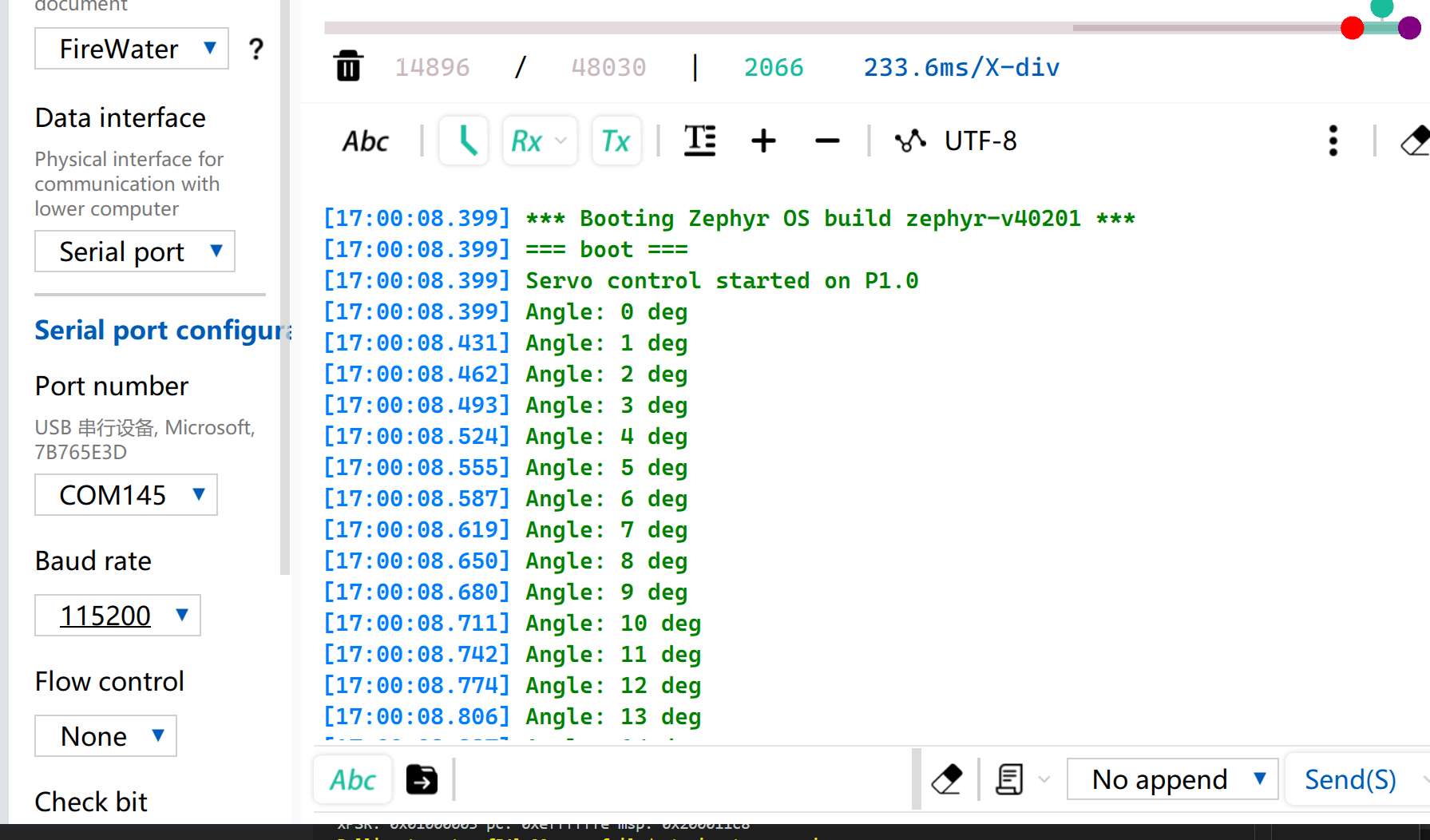
After the sketch is uploaded, the servo rotates from 0° to 180° at about 33 degrees per second, and then rotates back to 0°.
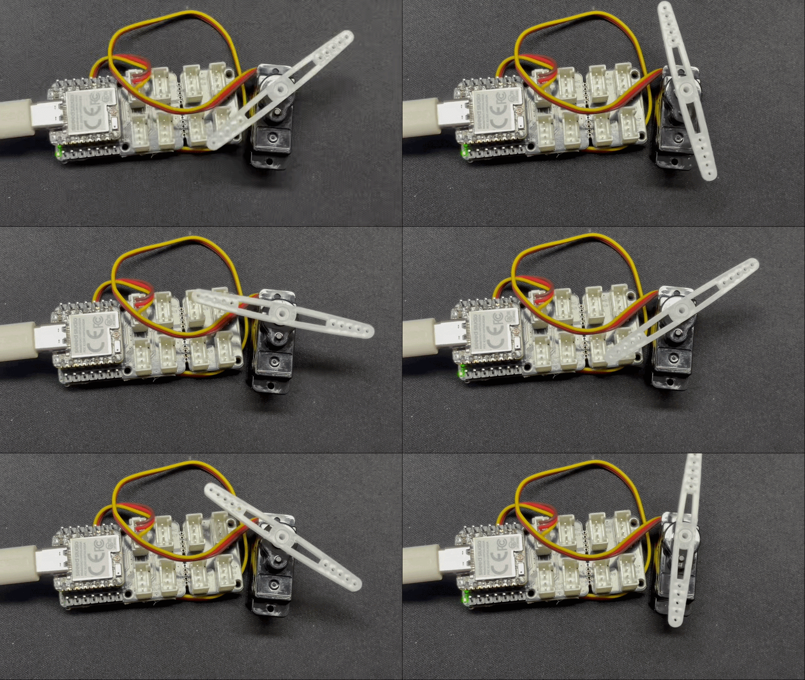
Meanwhile, the current servo angle will be printed via USB serial port.
Analog
Analog input is based on an Analog-to-Digital Converter (ADC), which converts a continuous voltage from an external sensor into a digital value. The raw ADC value can then be mapped to practical measurements such as soil moisture, battery voltage, or temperature.
Hardware Preparation
| Seeed Studio XIAO nRF54LM20A Sense | Seeed Studio Grove Base for XIAO | Grove - Capacitive Soil Moisture Sensor |
|---|---|---|
| |  |
Software Preparation
According to the pinout of the XIAO nRF54LM20A, A0 / P1.00 can be used as an analog input pin.
- For the pinout of the XIAO nRF54LM20A, click XIAO nRF54LM20A Pin List to view details.
Create a new Arduino sketch, read the analog value from A0 / P1.00, and print the raw ADC value through USB serial every 500 ms.
#include <Arduino.h>

#define ADC_PIN A0

void setup()
{
  Serial.begin(115200);
  delay(1000);

  Serial.println("ADC demo - XIAO nRF54LM20A Arduino");
  Serial.println("Reading analog input on P1.00 / AIN0 / A0");

  analogReadResolution(12);
}

void loop()
{
  int raw = analogRead(ADC_PIN);

  Serial.print("ADC raw: ");
  Serial.println(raw);

  delay(500);
}
Result
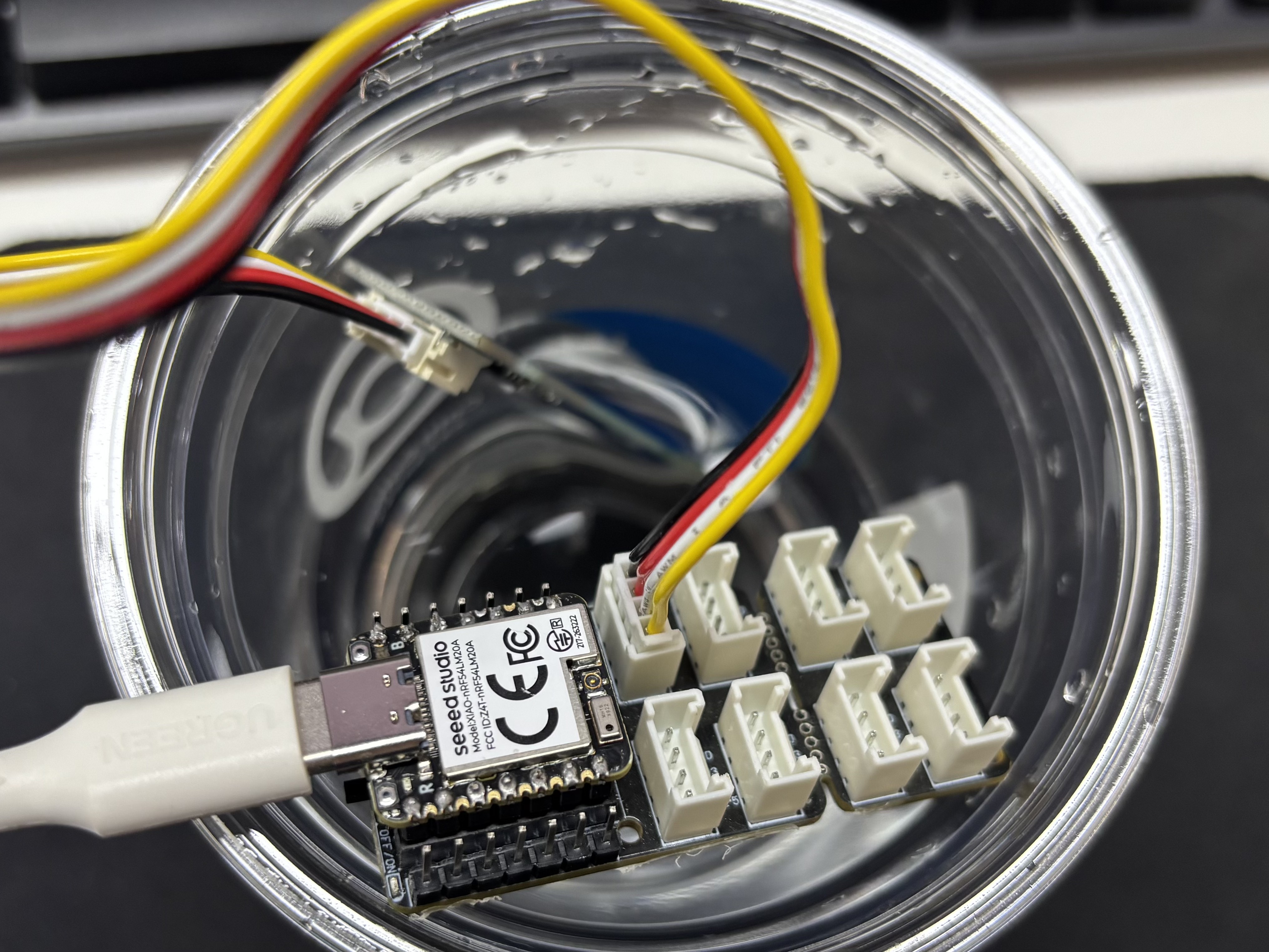
After flashing the program, insert the Grove-Capacitive Soil Moisture Sensor into household potted plants.
Open the serial port assistant on your computer and observe the output values.
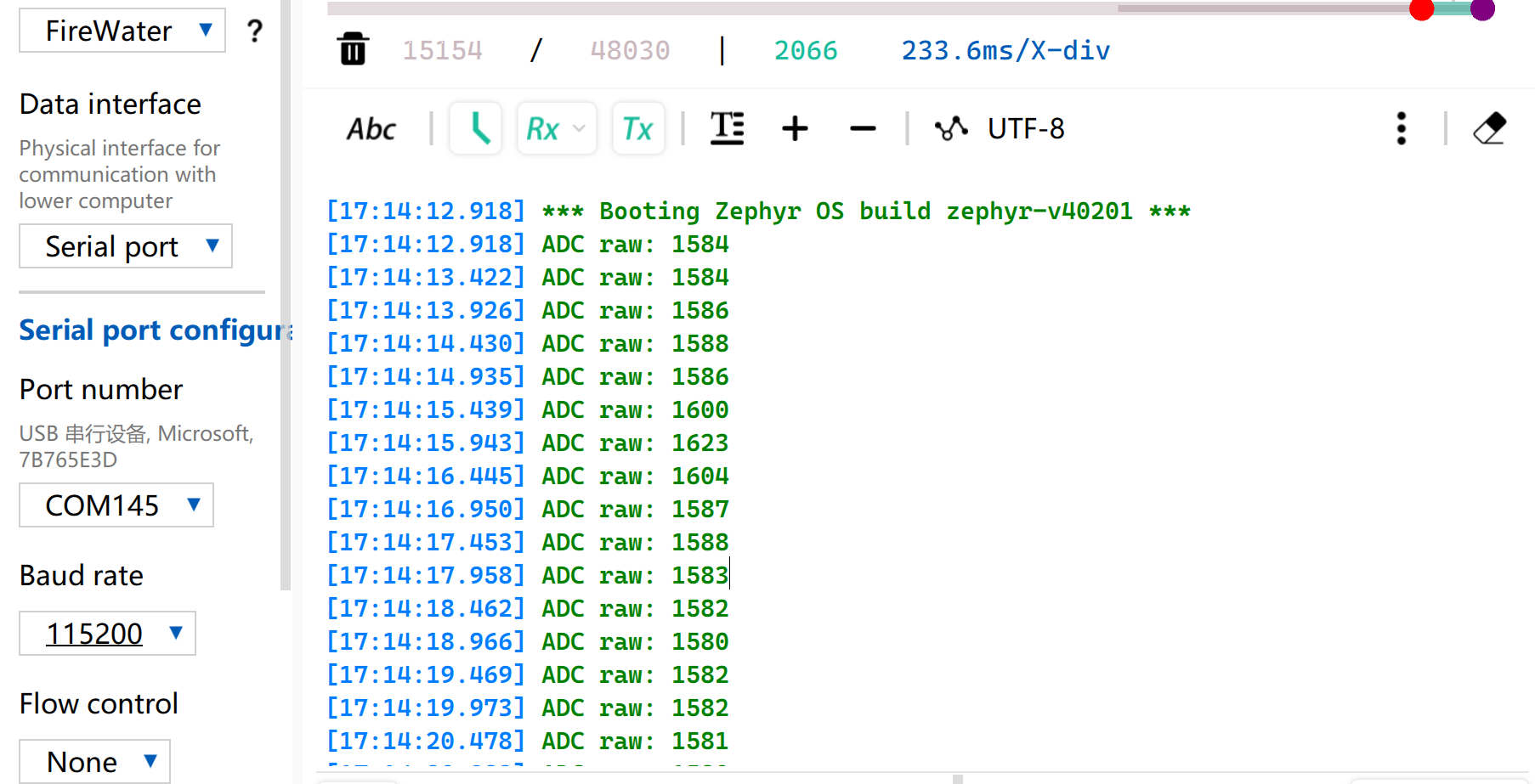
Voltage Reference Reading Table
| Status | Sensor Output Voltage | Expected ADC Raw Value |
|---|---|---|
| In air (Dry) | ~2.0–2.4V | ~3400–4095 |
| In moist soil | ~1.3–1.8V | ~2200–3000 |
| Fully immersed in water | ~0.8–1.2V | ~1365–2048 |
Due to individual differences in components, different module measurements in the same environment may vary.
UART
Universal Asynchronous Receiver/Transmitter (UART) is a standard asynchronous serial protocol. It does not require a shared clock; both devices communicate using the same configured baud rate. With TX and RX cross-connected and GND shared, UART provides a simple full-duplex link for console logs, module debugging, and low-bandwidth point-to-point communication.
Hardware Preparation
| Seeed Studio XIAO nRF54LM20A Sense | USB to TTL Converter |
|---|---|
|  |
Software Preparation
According to the pinout of the XIAO nRF54LM20A, D6 / P1.08 and D7 / P1.09 can be used as TX and RX pins for external UART communication.
- For the pinout of the XIAO nRF54LM20A, click XIAO nRF54LM20A Pin List to view details.
Create a new Arduino sketch. The example sends a startup message through the external UART, echoes received characters, and periodically prints a heartbeat message.
Arduino sketch
#include <Arduino.h>

#define RX_BUF_SIZE 128
#define TX_BUF_SIZE 256
#define HEARTBEAT_INTERVAL_MS 5000

static char rx_buf[RX_BUF_SIZE];
static size_t rx_buf_pos = 0;
static char tx_buf[TX_BUF_SIZE];

static uint32_t heartbeat_count = 0;
static unsigned long last_heartbeat = 0;

static void uart_send_string(const char *str)
{
  Serial1.print(str);
}

static void handle_complete_line()
{
  rx_buf[rx_buf_pos] = '\0';

  if (rx_buf_pos > 0) {
    Serial.print("Received: ");
    Serial.println(rx_buf);

    uart_send_string("\r\nYou sent: ");
    uart_send_string(rx_buf);
  }

  uart_send_string("\r\n");
  rx_buf_pos = 0;
  memset(rx_buf, 0, sizeof(rx_buf));
}

static void process_rx_byte(char c)
{
  static bool last_was_cr = false;

  if (c == '\r' || c == '\n') {
    if (c == '\n' && last_was_cr) {
      last_was_cr = false;
      return;
    }

    uart_send_string("\r\n");
    handle_complete_line();
    last_was_cr = (c == '\r');
    return;
  }

  last_was_cr = false;

  Serial1.write(c);

  if (rx_buf_pos < RX_BUF_SIZE - 1) {
    rx_buf[rx_buf_pos++] = c;
    return;
  }

  uart_send_string("\r\n[Warning] Input too long, buffer cleared.\r\n");
  rx_buf_pos = 0;
  memset(rx_buf, 0, sizeof(rx_buf));
}

void setup()
{
  Serial.begin(115200);
  delay(1000);

  Serial.println("========================================");
  Serial.println("  UART demo for XIAO nRF54LM20A");
  Serial.println("========================================");

  Serial1.begin(115200);

  uart_send_string("\r\n");
  uart_send_string("========================================\r\n");
  uart_send_string("  UART demo for XIAO nRF54LM20A\r\n");
  uart_send_string("========================================\r\n");
  uart_send_string("\r\n");
  uart_send_string("Pin Configuration:\r\n");
  uart_send_string("  TX: P1.08 / D6\r\n");
  uart_send_string("  RX: P1.09 / D7\r\n");
  uart_send_string("  Baud Rate: 115200\r\n");
  uart_send_string("\r\n");
  uart_send_string("Type something and press Enter to see it echoed.\r\n");
  uart_send_string("\r\n");

  Serial.println("UART demo started. Waiting for data...");
  Serial.println("Connect USB-TTL RX to D6/TX, TX to D7/RX, and GND to GND.");

  last_heartbeat = millis();
}

void loop()
{
  while (Serial1.available() > 0) {
    char c = (char)Serial1.read();
    process_rx_byte(c);
  }

  unsigned long now = millis();
  if (now - last_heartbeat >= HEARTBEAT_INTERVAL_MS) {
    last_heartbeat = now;
    heartbeat_count++;

    snprintf(tx_buf, sizeof(tx_buf),
             "\r\n[Heartbeat #%lu] UART running...\r\n",
             (unsigned long)heartbeat_count);

    uart_send_string(tx_buf);

    Serial.print("Heartbeat #");
    Serial.print(heartbeat_count);
    Serial.println(" sent");
  }

  delay(10);
}
Result
- Wire according to the table order
| XIAO nRF54LM20A | CH340 |
|---|---|
| VBUS | 5V |
| GND | GND |
| P1.08 - TX | RX |
| P1.09 - RX | TX |
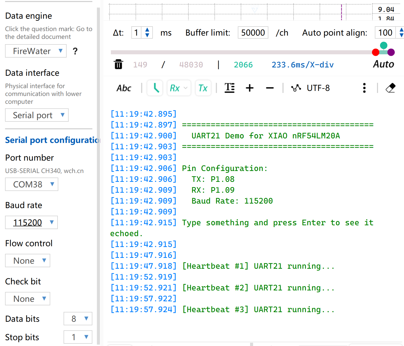
- Open the serial port monitoring software on your computer. The external UART will print the configured pin information at startup. By default, the string
[Heartbeat #number] UART running...will be printed periodically. If you type characters into the external serial tool and press Enter, the board will echo the received line.
I2C
I2C is a synchronous, half-duplex communication protocol that uses two lines: SDA for data and SCL for clock. Multiple devices can share the same bus through addressing, making I2C a common choice for sensors, IMUs, temperature and humidity modules, and small OLED displays.
Hardware Preparation
| Seeed Studio XIAO nRF54LM20A Sense | Seeed Studio Expansion Board Base for XIAO |
|---|---|
|  |
Software Preparation
According to the pinout of the XIAO nRF54LM20A, D4 / P1.03 and D5 / P1.07 can be configured as I2C SDA and SCL pins.
- For the pinout of the XIAO nRF54LM20A, click XIAO nRF54LM20A Pin List to view details.
- Install the following libraries from Arduino IDE > Tools > Manage Libraries...:
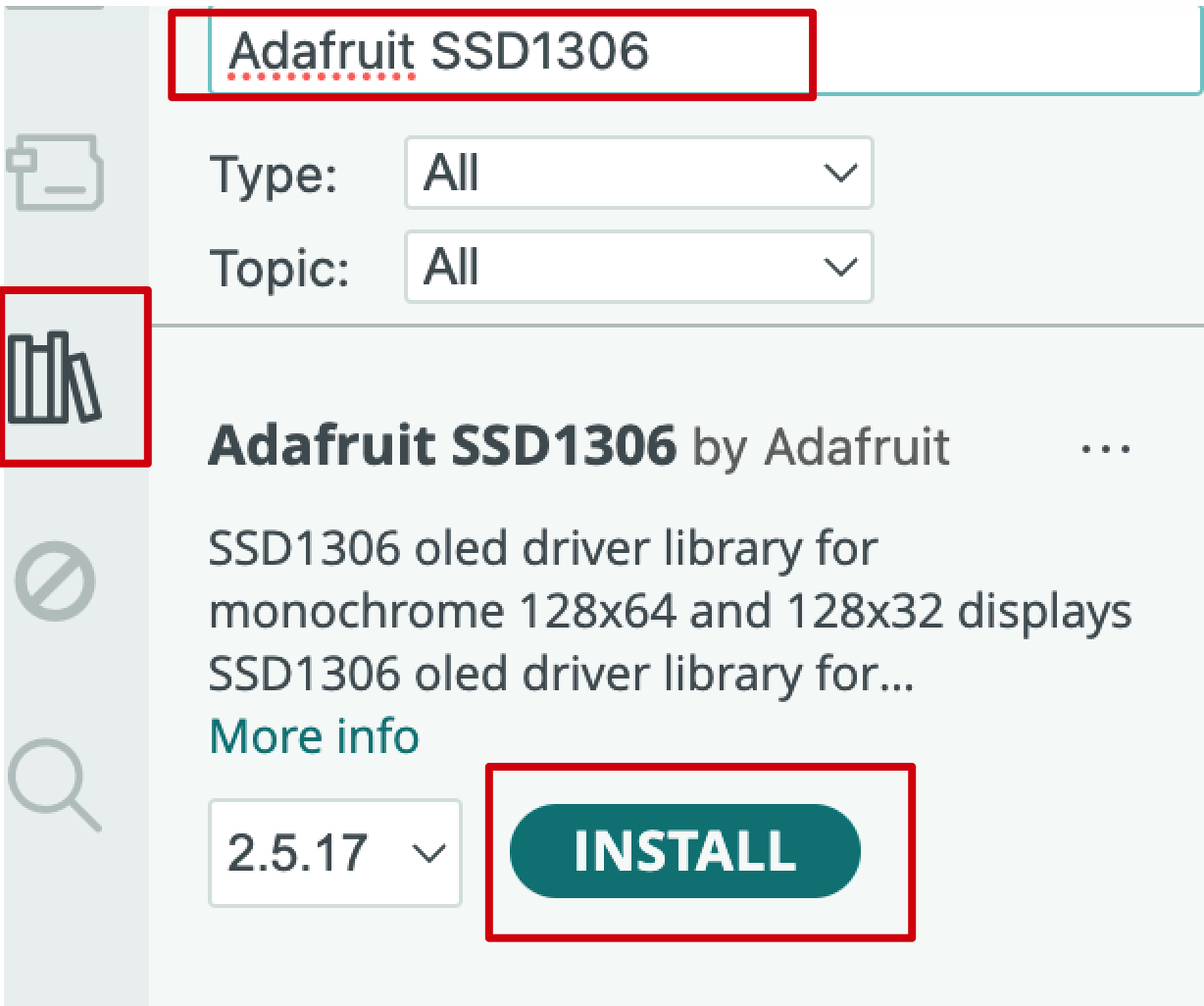
- Adafruit SSD1306
- Adafruit GFX Library
- Adafruit BusIO
- Create a new Arduino sketch to initialize the OLED and display text.
Arduino sketch
#include <Arduino.h>
#include <Wire.h>
#include <Adafruit_GFX.h>
#include <Adafruit_SSD1306.h>

#define OLED_W 128
#define OLED_H 64
#define OLED_ADDR 0x3C
#define OLED_RESET -1

#define OLED_SDA PIN_D4
#define OLED_SCL PIN_D5

Adafruit_SSD1306 display(OLED_W, OLED_H, &Wire, OLED_RESET);

void setup() {
  Serial.begin(115200);
  delay(1000);

  Serial.println("SSD1306 OLED test with pull-ups");

  Wire.setPins(OLED_SDA, OLED_SCL);
  Wire.begin();
  Wire.setClock(100000);

  pinMode(OLED_SDA, INPUT_PULLUP);
  pinMode(OLED_SCL, INPUT_PULLUP);
  delay(20);

  Serial.print("SDA idle = ");
  Serial.println(digitalRead(OLED_SDA));
  Serial.print("SCL idle = ");
  Serial.println(digitalRead(OLED_SCL));

  if (!display.begin(SSD1306_SWITCHCAPVCC, OLED_ADDR, true, false)) {
    Serial.println("SSD1306 init failed");
    while (1) {
      delay(1000);
    }
  }

  Serial.println("SSD1306 init OK");

  display.clearDisplay();
  display.setTextColor(SSD1306_WHITE);
  display.setTextSize(1);

  display.setCursor(28, 20);
  display.println("Hello XIAO");

  display.setCursor(24, 36);
  display.println("nRF54LM20A");

  display.display();
}

void loop() {
}
Result
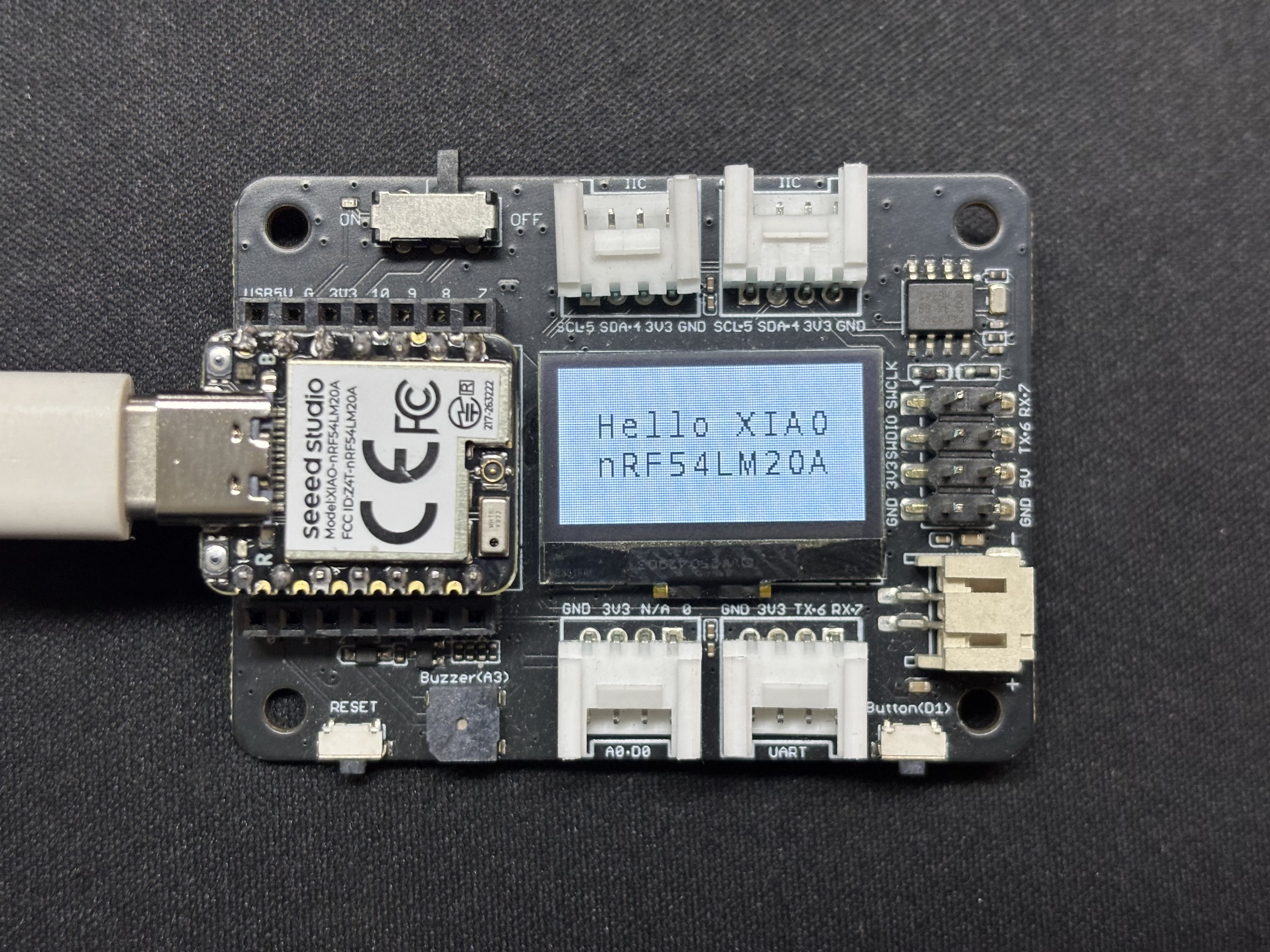
After the program runs, the text Hello XIAO nRF54LM20A will be displayed on the OLED, and the initialization status will be printed through the USB serial port.
SPI
SPI is a high-speed, synchronous, full-duplex communication protocol. It uses a dedicated SCLK line for timing, MOSI and MISO lines for data, and a CS/SS line to select the target device. Because SPI can provide high throughput with simple hardware, it is widely used for flash storage, SD cards, high-refresh-rate displays, and high-speed sensors.
Hardware Preparation
| Seeed Studio XIAO nRF54LM20A Sense | Round Display for Seeed Studio XIAO |
|---|---|
|  |
Software Preparation
- For the pinout of the XIAO nRF54LM20A, click XIAO nRF54LM20A Pin List to view details.
- Install the following libraries from Arduino IDE > Tools > Manage Libraries...:
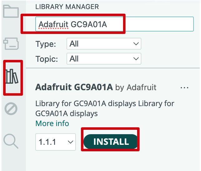
- Adafruit GC9A01A
- Adafruit GFX Library
- Adafruit BusIO
- Create a new Arduino sketch and write the solid-color screen filling logic.
Arduino sketch
#include <Arduino.h>
#include <Adafruit_GFX.h>
#include <Adafruit_GC9A01A.h>

#define TFT_CS    PIN_D1
#define TFT_DC    PIN_D3
#define TFT_MOSI  PIN_D10
#define TFT_SCLK  PIN_D8
#define TFT_RST   -1
#define TFT_BL    PIN_D6

#define LCD_W  240
#define LCD_H  240

#define COLOR_BLACK   0x0000U
#define COLOR_WHITE   0xFFFFU
#define COLOR_RED     0xF800U
#define COLOR_GREEN   0x07E0U
#define COLOR_BLUE    0x001FU
#define COLOR_YELLOW  0xFFE0U
#define COLOR_CYAN    0x07FFU
#define COLOR_MAGENTA 0xF81FU
#define COLOR_ORANGE  0xFD20U

Adafruit_GC9A01A tft(TFT_CS, TFT_DC, TFT_MOSI, TFT_SCLK, TFT_RST);

static void fill_screen(uint16_t color)
{
  tft.fillScreen(color);
}

static void demo_solid_colors()
{
  static const uint16_t colors[] = {
    COLOR_RED, COLOR_ORANGE, COLOR_YELLOW,
    COLOR_GREEN, COLOR_CYAN, COLOR_BLUE, COLOR_MAGENTA,
  };

  static const char *names[] = {
    "RED", "ORANGE", "YELLOW", "GREEN", "CYAN", "BLUE", "MAGENTA",
  };

  for (int i = 0; i < 7; i++) {
    Serial.print("Solid: ");
    Serial.println(names[i]);

    fill_screen(colors[i]);
    delay(600);
  }
}

static void demo_color_bars()
{
  static const uint16_t bar_colors[] = {
    COLOR_RED, COLOR_ORANGE, COLOR_YELLOW,
    COLOR_GREEN, COLOR_BLUE, COLOR_MAGENTA,
  };

  const int BAR_W = LCD_W / 6;

  for (int i = 0; i < 6; i++) {
    tft.fillRect(i * BAR_W, 0, BAR_W, LCD_H, bar_colors[i]);
  }

  Serial.println("Color bars");
  delay(2000);
}

void setup()
{
  Serial.begin(115200);
  delay(1000);

  Serial.println("GC9A01 demo - XIAO nRF54LM20A Arduino");

  pinMode(TFT_BL, OUTPUT);
  digitalWrite(TFT_BL, HIGH);

  tft.begin();
  tft.setRotation(0);
  tft.fillScreen(COLOR_BLACK);

  Serial.println("Display ready, starting demo loop");
}

void loop()
{
  demo_solid_colors();
  demo_color_bars();
}
Result
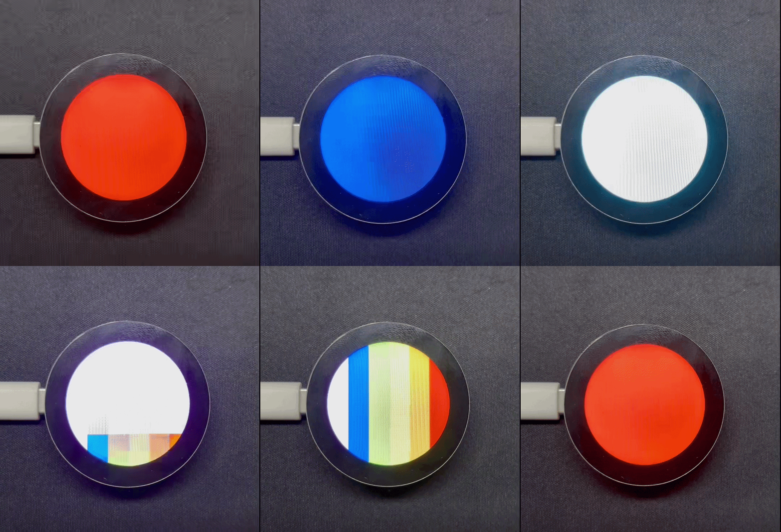
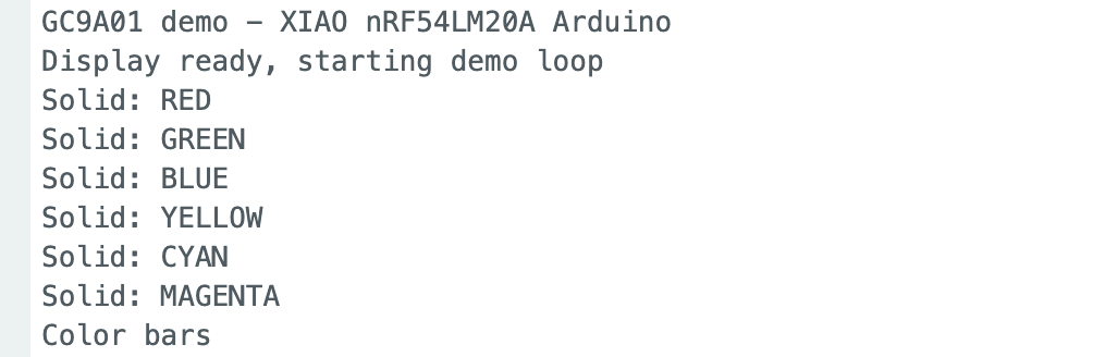
After uploading the sketch, the program refreshes the screen in the sequence of red, orange, yellow, green, cyan, blue, and magenta, and then displays colorful striped patterns.
The Serial Monitor output is shown below:
Special Thanks
Special thanks to lolren for contributing the Arduino adaptation for XIAO nRF54LM20A. The code and README are clear and helpful. If you would like to learn more about using XIAO nRF54LM20A with Arduino, refer to the GitHub links below.
Tech Support & Product Discussion
Thank you for choosing our products! We are here to provide you with different support to ensure that your experience with our products is as smooth as possible. We offer several communication channels to cater to different preferences and needs.