Low Power Modes for XIAO nRF54LM20A Sense
The XIAO nRF54LM20A is built around the nRF54LM20 SoC and features ultra-low power consumption. Its outstanding low-power performance effectively extends device runtime for battery-critical applications such as wearables, IoT end nodes and remote sensing units. This document describes how to implement and deploy various low-power modes on the XIAO nRF54LM20A.
This tutorial is developed based on the PlatformIO build system and Zephyr RTOS. If you are not familiar with creating a project for the XIAO nRF54LM20A under PlatformIO, you can jump to Getting Sarted With Seeed Studio XIAO nRF54LM20A.
Hardware Preperation
| SeeedStudio XIAO nRF54LM20A Sense |
|---|
Powered by battery
All modes implemented in this chapter adopt battery power supply via the bottom pads of the XIAO nRF54LM20A instead of USB-C power feeding. The XIAO nRF54LM20A is capable of using a 3.7V lithium battery as the power supply input. You can refer to the following diagram for the wiring method.
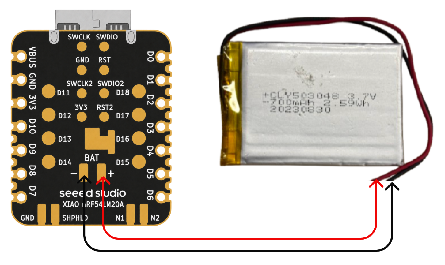
Please be careful not to short-circuit the positive and negative terminals and burn the battery and equipment when soldering. If the battery has power, never solder it onto the board, as this may burn out the circuit board. Short-circuiting while the circuit is powered on poses a significant risk; it is recommended to use an adapter.
Low-power mode
Low-power mode is implemented on the XIAO nRF54LM20A using functions such as System ON Sleep. In this mode, power consumption is reduced while the system remains operational. The CPU clock is gated and suspended, yet RAM contents, peripheral states and program context are fully preserved, and low-power timers including GRTC keep running. This section verifies the low-power mode with the k_sleep function and BLE advertising.
Software
- Modify the device tree file ending with
.overlay.
/ {
    chosen {
        zephyr,bt-hci = &bt_hci_controller;
    };
};

&bt_hci_controller {
    status = "okay";
};

/* Disable unused regulators to reduce standby power */
&power_en {
    /delete-property/ regulator-boot-on;
};

&pmic {
    regulators {
        LDO1 {
            /delete-property/ regulator-boot-on;
        };
    };
};
- Modify the
prj.confconfiguration file to enable system power management settings.
CONFIG_GPIO=y
CONFIG_ARM_MPU=n
CONFIG_NRFX_POWER=y
CONFIG_POWEROFF=y
CONFIG_HWINFO=y
CONFIG_CRC=y

# Device power management (peripheral level)
CONFIG_PM_DEVICE=y
CONFIG_PM_DEVICE_RUNTIME=y

# Bluetooth
CONFIG_BT=y
CONFIG_BT_BROADCASTER=y
CONFIG_BT_DEVICE_NAME="XIAO nRF54LM20A"
CONFIG_BT_CTLR_ASSERT_OPTIMIZE_FOR_SIZE=n
CONFIG_BT_CTLR_ASSERT_DEBUG=n
CONFIG_BT_CTLR_ASSERT_OVERHEAD_START=n
- Modify the main.c program, enable low-power mode with
k_sleep(K_SECONDS(10))and configure BLE to broadcast messages periodically at a 1-second interval.
/*
* BLE Low Power Broadcasting Demo for XIAO nRF54LM20A
*/
#include <zephyr/kernel.h>
#include <zephyr/bluetooth/bluetooth.h>
#include <zephyr/bluetooth/hci.h>
/* 1000ms / 0.625ms = 1600 = 0x0640 */
#define ADV_INTERVAL_1S 0x0640
static const struct bt_data ad[] = {
BT_DATA_BYTES(BT_DATA_FLAGS, (BT_LE_AD_GENERAL | BT_LE_AD_NO_BREDR)),
BT_DATA(BT_DATA_NAME_COMPLETE, "XIAO nRF54LM20A", 15),
};
static void bt_ready(int err)
{
if (err) {
return;
}
struct bt_le_adv_param param = BT_LE_ADV_PARAM_INIT(
BT_LE_ADV_OPT_NONE,
ADV_INTERVAL_1S,
ADV_INTERVAL_1S,
NULL
);
bt_le_adv_start(¶m, ad, ARRAY_SIZE(ad), NULL, 0);
}
int main(void)
{
bt_enable(bt_ready);
/* BLE controller handles advertising autonomously; CPU sleeps */
while (1) {
k_sleep(K_SECONDS(10));
}
return 0;
}
Result
After flashing the firmware, we can use a power consumption tester to measure the operating current of the XIAO nRF54LM20A under low-power conditions.
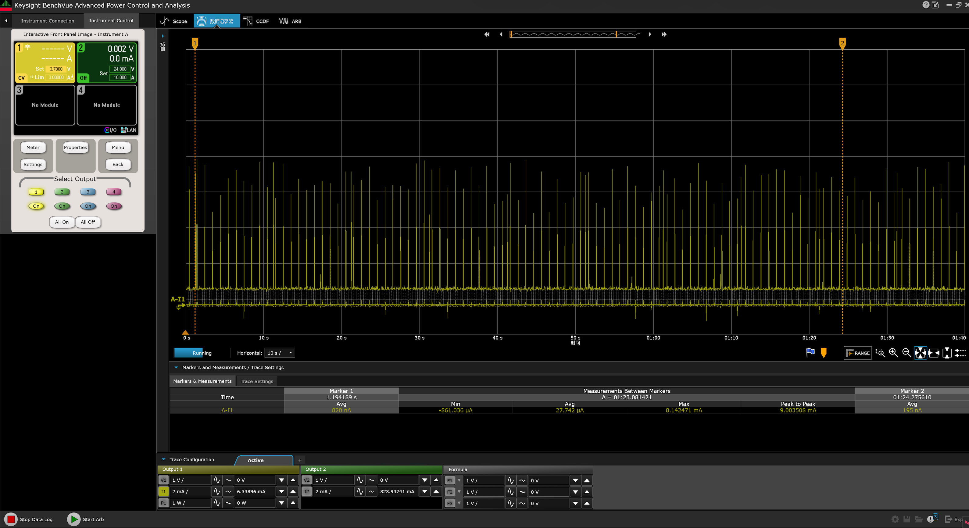
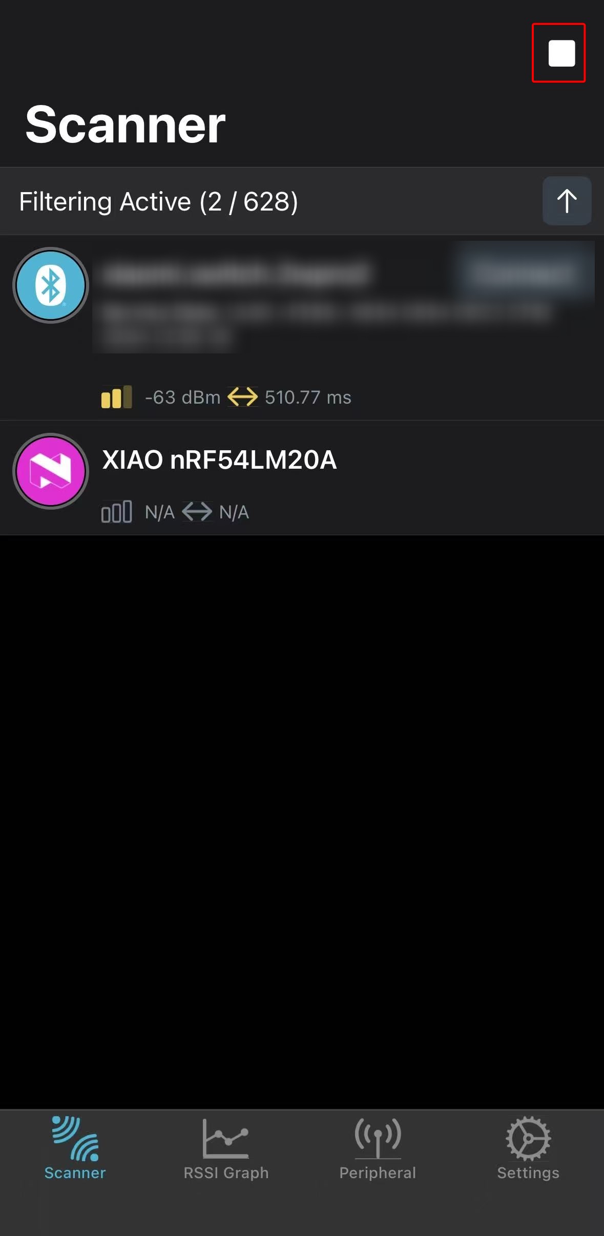
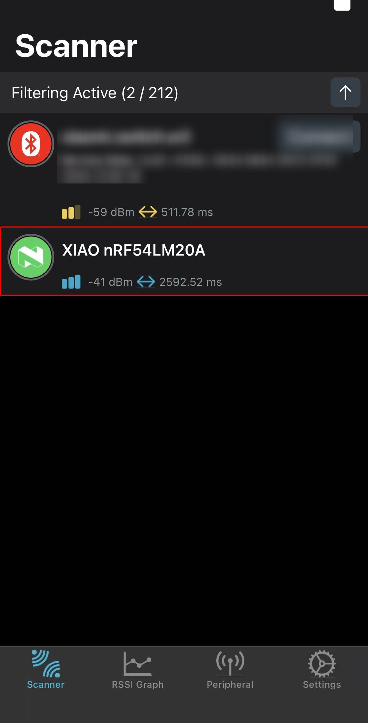
Meanwhile, you can scan via Bluetooth and find the device advertising under the name XIAO nRF54LM20A.
- Android: nRF Connect
- IOS: nRF Connect
 |  |
The above test results are measured under laboratory conditions. Values may vary with different environments and test instruments; refer to actual measured performance.
Ultra-Low Power Mode
The XIAO nRF54LM20A achieves ultra-low power mode via System OFF. Upon entering this mode, all peripheral clocks halt and most peripherals are fully powered down, resulting in a standby current as low as 5 µA. Wakeup triggers include the GRTC timer or GPIO interrupts. The system state is not retained; after wakeup, the chip behaves as if power-cycled and the program restarts from the main() function.
This section verifies the practical performance of System OFF mode on the XIAO nRF54LM20A using GPIO interrupt wakeup.
Software
In this example, the external flash must be manually placed into deep power-down mode, and its SPI pins must be driven to defined states; otherwise, it may introduce additional leakage current.
- Modify the device tree file with the
.overlaysuffix.
&power_en {
	/delete-property/ regulator-boot-on;
};

&pmic {
	regulators {
		LDO1 {
			/delete-property/ regulator-boot-on;
		};
	};
};

&pmic_leds {
	status = "disabled";
};

&py25q64 {
	status = "okay";
};
- Modify the
prj.conffile to enable configurations including power management.
CONFIG_SERIAL=y
CONFIG_CONSOLE=y
CONFIG_UART_CONSOLE=y
CONFIG_PRINTK=y
CONFIG_BOOT_BANNER=n

CONFIG_GPIO=y
CONFIG_SPI=y
CONFIG_FLASH=y
CONFIG_SPI_NOR=y

CONFIG_PM_DEVICE=y
CONFIG_PM_DEVICE_RUNTIME=y
CONFIG_POWEROFF=y
CONFIG_HWINFO=y

CONFIG_BT=n
- Write the main.c program to wake the chip from ultra-low power mode when the onboard Boot button is pressed.
main.c
/*
 * Copyright (c) 2019 Nordic Semiconductor ASA
 *
 * SPDX-License-Identifier: Apache-2.0
 */
/*
 * Ultra-low-power System OFF demo for XIAO nRF54LM20A Sense.
 *
 * Confirmed board resources from the board DTS:
 * - sw0 / BOOT: P0.09 (active low with pull-up)
 * - External flash (PY25Q64HA) on spi00:
 *   HOLD# P2.00, SCK P2.01, MOSI P2.02, WP# P2.03, MISO P2.04, CS# P2.05
 * - RGB LEDs on P1.22 / P1.23 / P1.24
 */
#include <errno.h>
#include <inttypes.h>
#include <stdio.h>

#include <zephyr/device.h>
#include <zephyr/drivers/gpio.h>
#include <zephyr/drivers/hwinfo.h>
#include <zephyr/kernel.h>
#include <zephyr/pm/device.h>
#include <zephyr/sys/poweroff.h>

static const struct gpio_dt_spec sw0 = GPIO_DT_SPEC_GET(DT_ALIAS(sw0), gpios);
static const struct gpio_dt_spec led_red = GPIO_DT_SPEC_GET(DT_ALIAS(led1), gpios);
static const struct gpio_dt_spec led_blue = GPIO_DT_SPEC_GET(DT_ALIAS(led0), gpios);
static const struct gpio_dt_spec led_green = GPIO_DT_SPEC_GET(DT_ALIAS(led2), gpios);

#if DT_NODE_EXISTS(DT_CHOSEN(zephyr_console))
static const struct device *const cons = DEVICE_DT_GET(DT_CHOSEN(zephyr_console));
#endif

#if DT_NODE_HAS_STATUS(DT_NODELABEL(py25q64), okay)
static const struct device *const flash_dev = DEVICE_DT_GET(DT_NODELABEL(py25q64));
static const struct device *const flash_bus = DEVICE_DT_GET(DT_BUS(DT_NODELABEL(py25q64)));
#endif

static void print_reset_cause(uint32_t reset_cause)
{
	if (reset_cause & RESET_DEBUG) {
		printf("Reset by debugger.\n");
	} else if (reset_cause & RESET_CLOCK) {
		printf("Wakeup from System OFF by clock source.\n");
	} else if (reset_cause & RESET_LOW_POWER_WAKE) {
		printf("Wakeup from System OFF by GPIO.\n");
	} else if (reset_cause != 0U) {
		printf("Other wake up cause 0x%08" PRIX32 ".\n", reset_cause);
	} else {
		printf("Power-on reset or reset cause unavailable.\n");
	}
}

static int configure_gpio_wakeup(void)
{
	int rc;

	if (!gpio_is_ready_dt(&sw0)) {
		printf("sw0 GPIO device not ready.\n");
		return -ENODEV;
	}

	rc = gpio_pin_configure_dt(&sw0, GPIO_INPUT);
	if (rc < 0) {
		printf("Could not configure sw0 GPIO (%d)\n", rc);
		return rc;
	}

	rc = gpio_pin_interrupt_configure_dt(&sw0, GPIO_INT_LEVEL_ACTIVE);
	if (rc < 0) {
		printf("Could not configure sw0 GPIO interrupt (%d)\n", rc);
		return rc;
	}

	return 0;
}

static void release_led(const struct gpio_dt_spec *led, const char *name)
{
	int rc;

	if (!gpio_is_ready_dt(led)) {
		return;
	}

	rc = gpio_pin_configure(led->port, led->pin, GPIO_DISCONNECTED);
	if (rc < 0) {
		printf("Warning: could not disconnect %s (%d)\n", name, rc);
	}
}

static void release_led_gpios(void)
{
	release_led(&led_red, "red LED");
	release_led(&led_blue, "blue LED");
	release_led(&led_green, "green LED");
}

/*
 * Put the external flash pins into deterministic, low-leakage states before
 * System OFF. These pin numbers are confirmed by the board pinctrl and DTS.
 */
static int configure_spi_pins_for_system_off(void)
{
	const struct device *gpio2 = DEVICE_DT_GET(DT_NODELABEL(gpio2));
	int rc;

	if (!device_is_ready(gpio2)) {
		printf("GPIO2 not ready.\n");
		return -ENODEV;
	}

	rc = gpio_pin_configure(gpio2, 5, GPIO_OUTPUT_HIGH);
	if (rc < 0) {
		return rc;
	}

	rc = gpio_pin_configure(gpio2, 0, GPIO_OUTPUT_HIGH);
	if (rc < 0) {
		return rc;
	}

	rc = gpio_pin_configure(gpio2, 3, GPIO_OUTPUT_HIGH);
	if (rc < 0) {
		return rc;
	}

	rc = gpio_pin_configure(gpio2, 1, GPIO_OUTPUT_LOW);
	if (rc < 0) {
		return rc;
	}

	rc = gpio_pin_configure(gpio2, 2, GPIO_OUTPUT_LOW);
	if (rc < 0) {
		return rc;
	}

	rc = gpio_pin_configure(gpio2, 4, GPIO_INPUT | GPIO_PULL_DOWN);
	if (rc < 0) {
		return rc;
	}

	return 0;
}

static int suspend_external_flash(void)
{
	int first_error = 0;
	int rc;

#if DT_NODE_HAS_STATUS(DT_NODELABEL(py25q64), okay)
	if (device_is_ready(flash_dev)) {
		rc = pm_device_action_run(flash_dev, PM_DEVICE_ACTION_SUSPEND);
		if ((rc < 0) && (first_error == 0)) {
			first_error = rc;
			printf("Warning: could not suspend external flash (%d)\n", rc);
		}
	} else {
		first_error = -ENODEV;
		printf("Warning: flash device is not ready; skipping driver DPD.\n");
	}

	if (device_is_ready(flash_bus)) {
		rc = pm_device_action_run(flash_bus, PM_DEVICE_ACTION_SUSPEND);
		if ((rc < 0) && (first_error == 0)) {
			first_error = rc;
			printf("Warning: could not suspend SPI bus (%d)\n", rc);
		}
	} else if (first_error == 0) {
		first_error = -ENODEV;
		printf("Warning: flash SPI bus is not ready.\n");
	}
#else
	first_error = -ENODEV;
	printf("Warning: py25q64 is not enabled in DTS.\n");
#endif

	rc = configure_spi_pins_for_system_off();
	if ((rc < 0) && (first_error == 0)) {
		first_error = rc;
		printf("Warning: could not configure flash SPI pins (%d)\n", rc);
	}

	return first_error;
}

static void suspend_console_best_effort(void)
{
#if DT_NODE_EXISTS(DT_CHOSEN(zephyr_console))
	int rc;

	if (!device_is_ready(cons)) {
		return;
	}

	rc = pm_device_action_run(cons, PM_DEVICE_ACTION_SUSPEND);
	if (rc < 0) {
		printf("Warning: could not suspend console (%d)\n", rc);
	}
#endif
}

int main(void)
{
	int rc;
	uint32_t reset_cause = 0U;

	printf("\n=== %s ultra-low-power system off demo ===\n", CONFIG_BOARD);

	rc = hwinfo_get_reset_cause(&reset_cause);
	if (rc == 0) {
		print_reset_cause(reset_cause);
	} else {
		printf("Warning: could not read reset cause (%d)\n", rc);
	}

	rc = configure_gpio_wakeup();
	if (rc < 0) {
		printf("Error: wakeup source configuration failed, aborting System OFF.\n");
		return 0;
	}

	release_led_gpios();

	rc = suspend_external_flash();
	if (rc < 0) {
		printf("Warning: flash low-power preparation incomplete (%d)\n", rc);
	}

	printf("Entering system off; press BOOT/SW0 to restart.\n");
	k_msleep(20);

	suspend_console_best_effort();

	rc = hwinfo_clear_reset_cause();
	if (rc < 0) {
		/* Clear failure should not stop entry into System OFF. */
		printf("Warning: could not clear reset cause (%d)\n", rc);
	}

	sys_poweroff();

	while (1) {
		k_sleep(K_FOREVER);
	}
}
Result
After startup, the firmware prepares the wakeup source and external peripherals, then automatically enters System OFF. The XIAO nRF54LM20A is measured with a power consumption tester, yielding an average operating current of approximately 3.74 µA when powered by a 3.7 V battery.
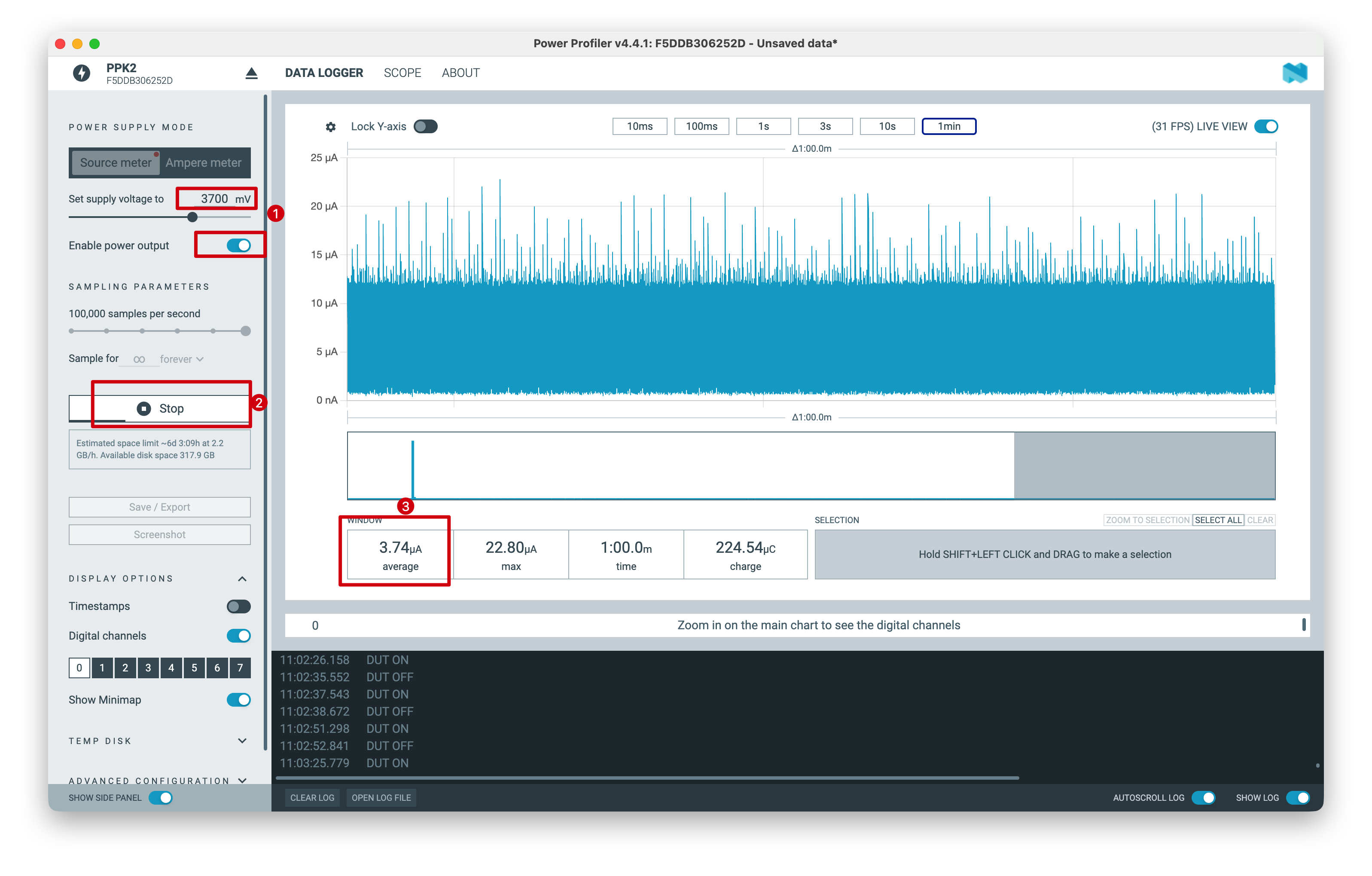
The above test results are measured under laboratory conditions. Values may vary with different environments and test instruments; refer to actual measured performance.
Tech Support & Product Discussion
Thank you for choosing our products! We are here to provide you with different support to ensure that your experience with our products is as smooth as possible. We offer several communication channels to cater to different preferences and needs.