Seeed Studio XIAO nRF54LM20A Sense With MicroPython
MicroPython is a Python interpreter with support for native code emission for performance-critical code. It provides a subset of core Python 3.6+ features, optimized for microcontrollers and resource-constrained systems. It differs from CPython, and you can read more about the differences in the MicroPython vs CPython differences page.
Using MicroPython with XIAO nRF54LM20A Sense
Next, I will guide you through how to use MicroPython on the XIAO nRF54LM20A Sense and program it with Thonny IDE, based on the Windows operating system.
Hardware Preparation
Before you start, you need to prepare a XIAO nRF54LM20A Sense development board.
| Seeed Studio XIAO nRF54LM20A Sense |
|---|
Install Thonny IDE
Choose the appropriate version for installation. Here, I am installing it on a Windows system, so I have selected the Windows version.
Follow the instructions for the desired Python version.
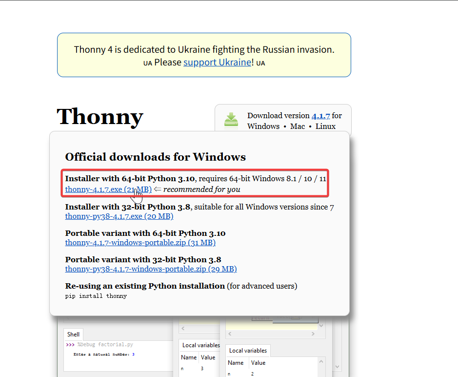
Then, simply follow the default steps for configuration.
Deploying MicroPython Firmware
Next, we will guide you through how to deploy the MicroPython firmware on the XIAO nRF54LM20A Sense.
Before flashing the firmware, connect the XIAO nRF54LM20A Sense to your computer
- Download Firmware Compressed Packet
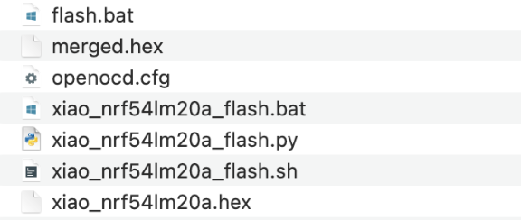
- Unzip Folder
The folder needs to be unzipped to any directory, and the contents of the following files will appear
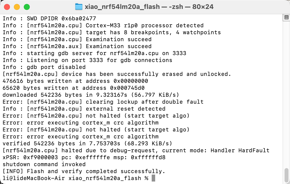
- Use a script to flash the MicroPython firmware
- For Windows, right-click in the extracted folder to open a PowerShell terminal and execute the flashing script,After the script is executed correctly, the output results are shown in the following figure
.\flash.bat
- For Mac/Linux
cd ~/xiao_nrf54lm20a_flash

sed -i '' $'s/\r$//' xiao_nrf54lm20a_flash.sh

chmod +x xiao_nrf54lm20a_flash.sh
./xiao_nrf54lm20a_flash.sh
Test the flashing effect
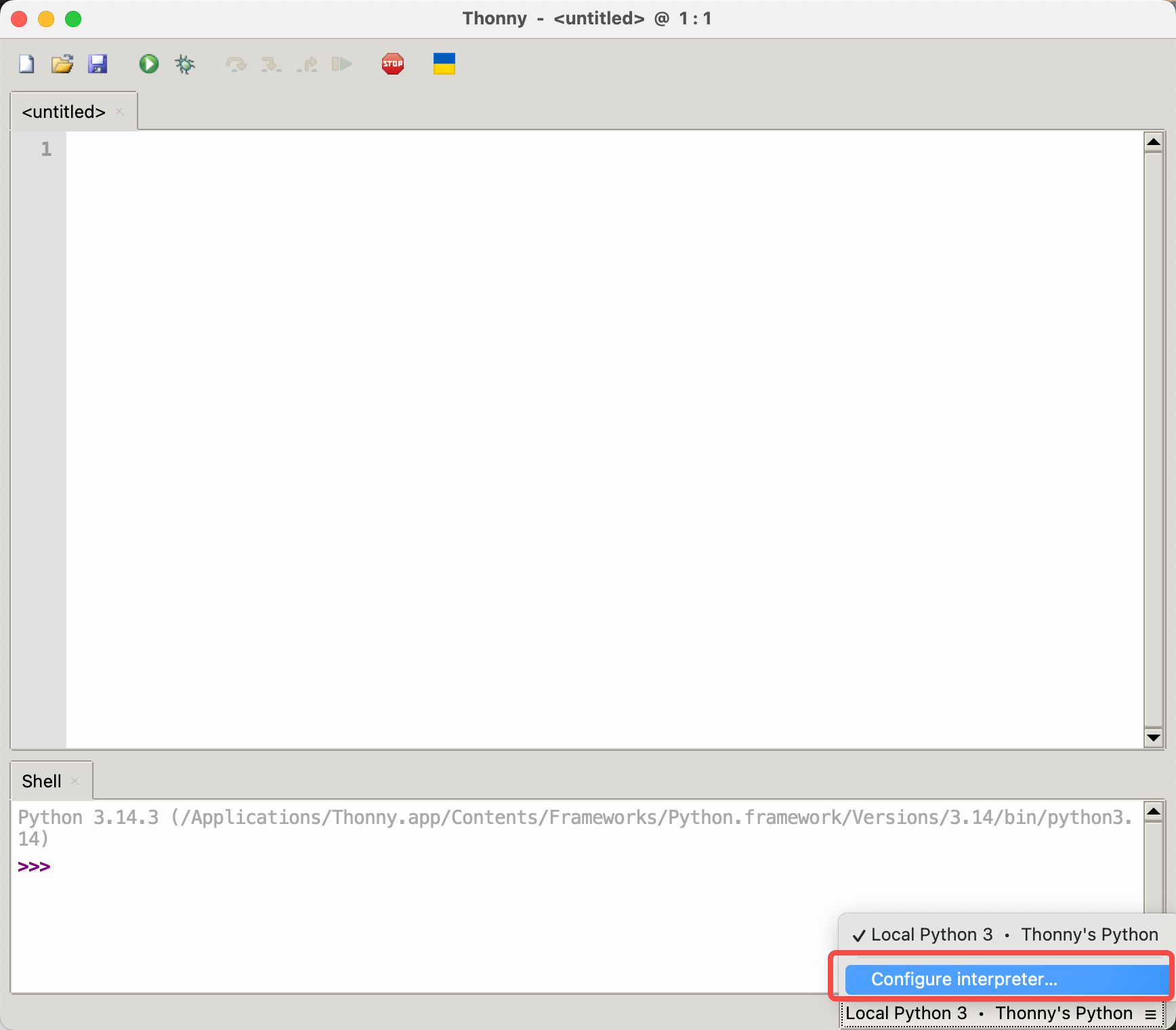
This chapter mainly guides you through configuring the Thonny IDE
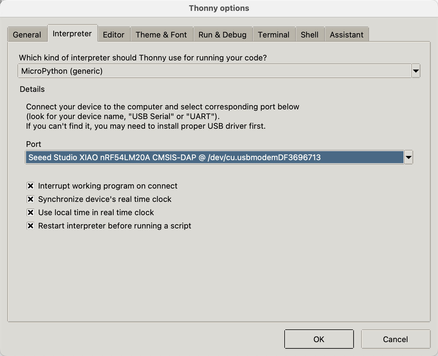
- Open Thonny IDE, click on the bottom right corner to prepare to select Configure interpreter
- Select MicroPython (generic), choose the corresponding Port based on the device, and click OK
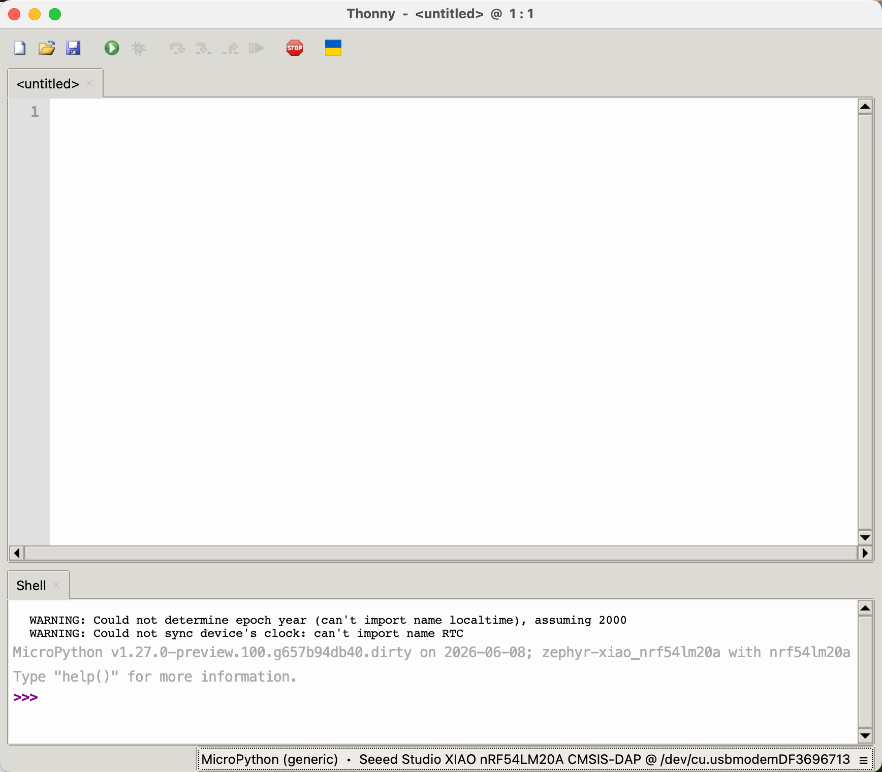
- After successful connection, it will be as shown in the figure below
- In File -> New, create a new file and perform a save test
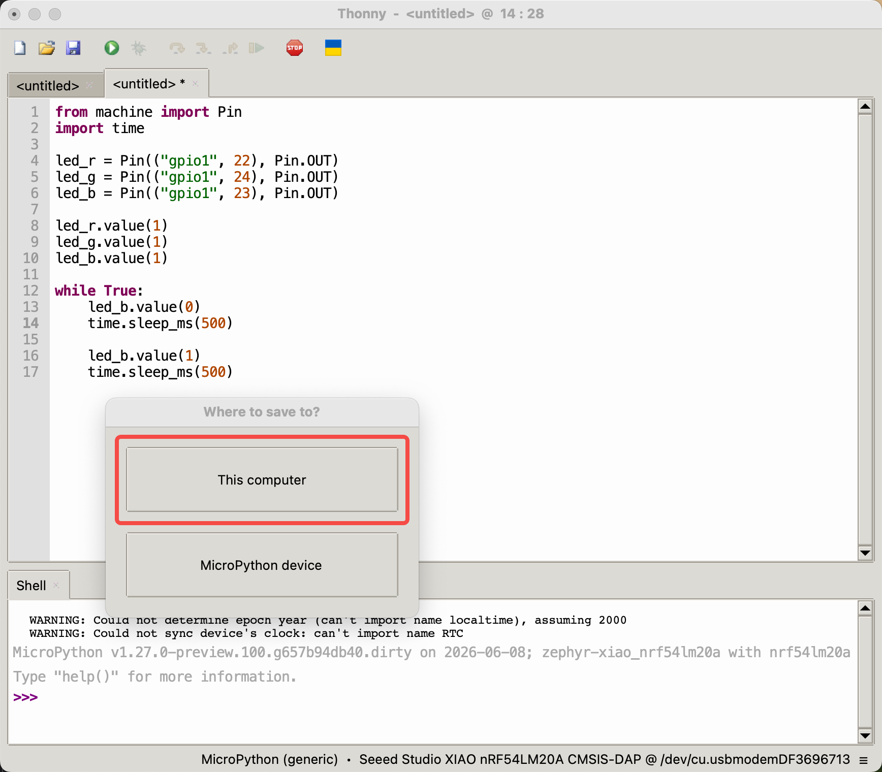
- After burning the firmware, write a Python program to make the RGB-B LED blink at a frequency of every 0.5 seconds
from machine import Pin
import time

led_r = Pin(("gpio1", 22), Pin.OUT)
led_g = Pin(("gpio1", 24), Pin.OUT)
led_b = Pin(("gpio1", 23), Pin.OUT)

led_r.value(1)
led_g.value(1)
led_b.value(1)

while True:
    led_b.value(0)
    time.sleep_ms(500)

    led_b.value(1)
    time.sleep_ms(500)
- Click the button in the upper left corner to run the program
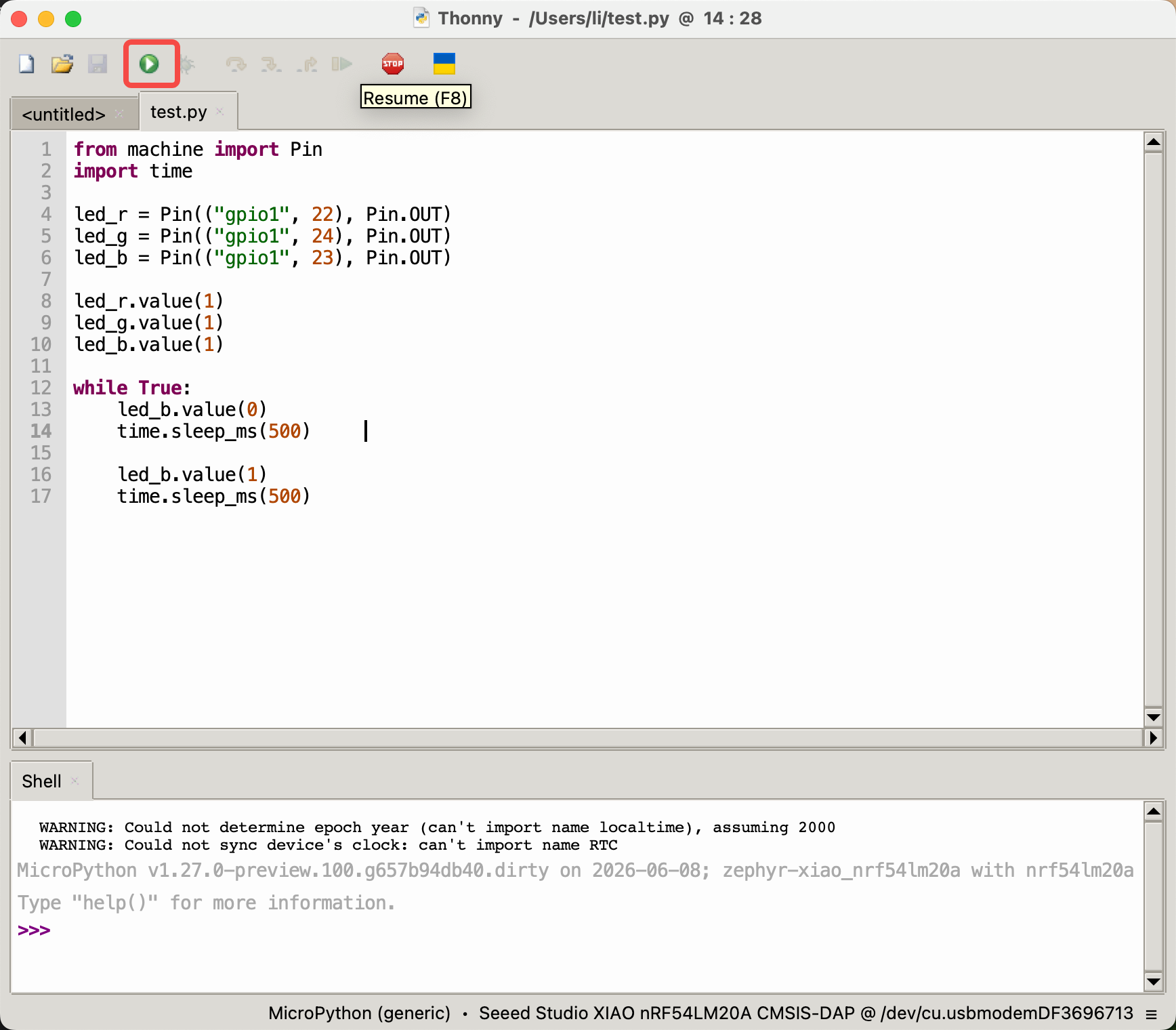
- The program's effect is shown in the figure
Digital
Digital pins are mainly used for on-off control of external sensors and actuators by outputting high and low logic levels. Combined with the Grove Base for XIAO expansion board and standard Grove peripheral modules, this section demonstrates how to use digital pins on the XIAO nRF54LM20A Sense with MicroPython.
Hardware Preparation
| Seeed Studio XIAO nRF54LM20A Sense | Seeed Studio Grove Base for XIAO | Grove - Piezo Buzzer | Grove - Button |
|---|---|---|---|
 |  |  | |
Software Preparation
According to the pinout of the XIAO nRF54LM20A Sense, D0 (P1.0) can be selected as the control pin for the Grove-Button, and D1 (P1.31) can be selected as the control pin for the Grove-Piezo Buzzer.
- For the pinout of the XIAO nRF54LM20A Sense, click XIAO nRF54LM20A Pin List to view details.
"""
Grove Button (D0 / P1.0) + Grove Piezo Buzzer (D1 / P1.31) - Digital mode
Button pressed → Buzzer ON; Button released → Buzzer OFF
"""

import time
from boards.xiao import XiaoPin

BUTTON = 0   # D0  → P1.0 (Grove Button, onboard pull-down)
BUZZER = 1   # D1  → P1.31 (Grove Piezo Buzzer)

try:
    button = XiaoPin(BUTTON, XiaoPin.IN)
    buzzer = XiaoPin(BUZZER, XiaoPin.OUT)
    buzzer.value(0)
    print("Digital demo started. Press the button to activate the buzzer.")

    while True:
        val = button.value()
        buzzer.value(val)
        time.sleep(0.01)

except KeyboardInterrupt:
    print("\nProgram interrupted by user")
except Exception as e:
    print("\nError occurred: %s" % {e})
finally:
    buzzer.value(0)
Code Explain:
- Imports & pin definitions:
XiaoPinfromboards.xiaoprovides GPIO control.BUTTON = 0maps to D0 (P1.0),BUZZER = 1maps to D1 (P1.31). - Initialization: The button pin is configured as input (the Grove Button has an onboard pull-down resistor — HIGH when pressed). The buzzer pin is configured as output, initialized to LOW (off).
- Main loop: Continuously reads the button state and writes it directly to the buzzer. When the button is pressed (HIGH), the buzzer turns on; when released (LOW), the buzzer turns off. A 10 ms sleep prevents busy-looping.
- Cleanup: The
finallyblock ensures the buzzer is turned off when the program exits.
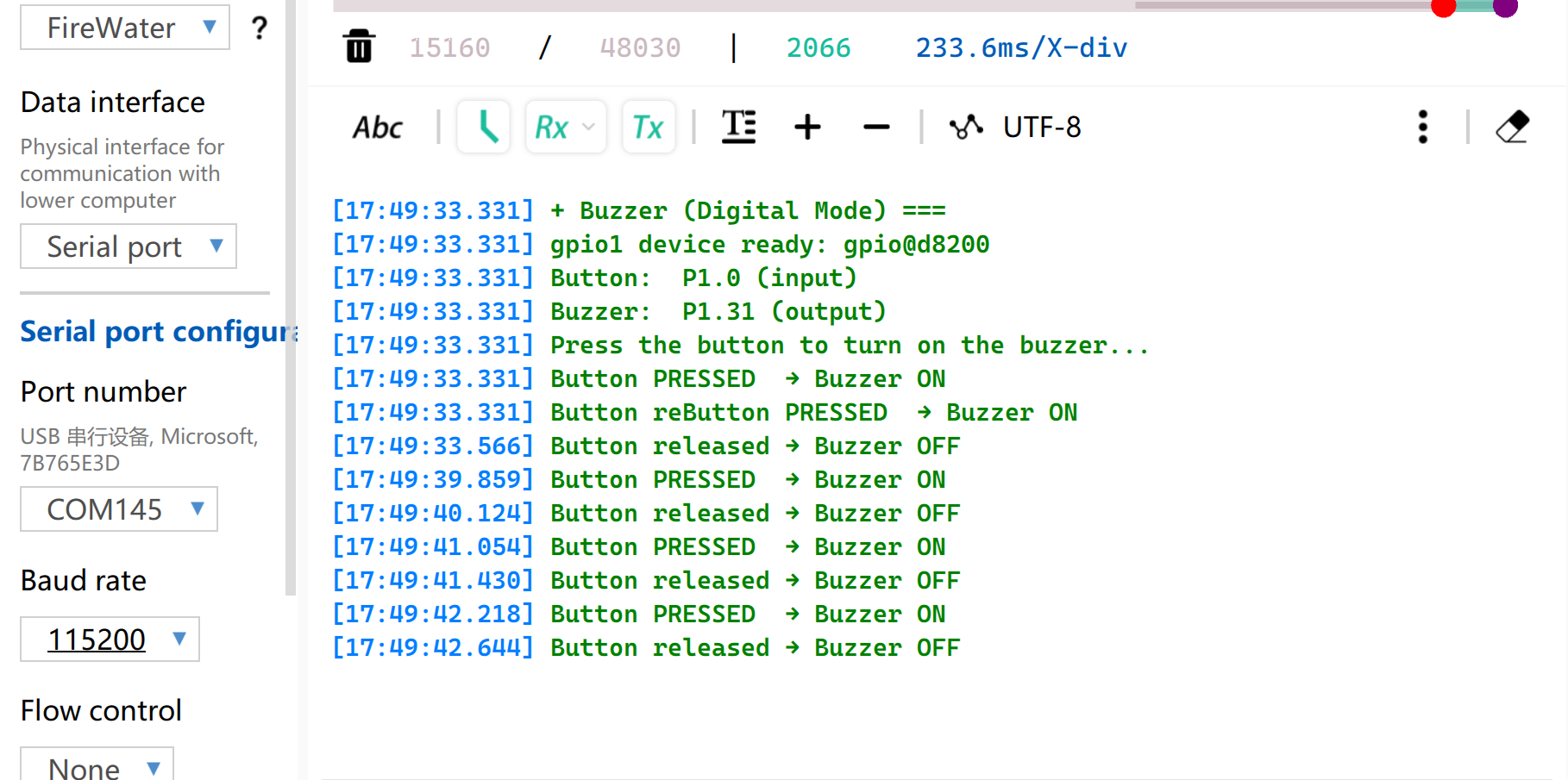
Result
After running the program, press the button and the buzzer will beep.
PWM
PWM rapidly switches pin levels at a fixed frequency and dynamically adjusts the duty cycle, outputting equivalent analog signals to peripherals. It is widely used for precise angle control of servo motors and smooth brightness adjustment of LEDs.
Hardware Preparation
| Seeed Studio XIAO nRF54LM20A Sense | Seeed Studio Grove Base for XIAO | Grove - Servo |
|---|---|---|
|  | |
Software Preparation
According to the pinout of the XIAO nRF54LM20A Sense, D0 (P1.0) can be selected as the control pin for the Grove-Servo.
- For the pinout of the XIAO nRF54LM20A Sense, click XIAO nRF54LM20A Pin List to view details.
"""
Servo control on D0 (P1.0) via PWM (50 Hz).
Sweeps 0 → 180° and back.
"""

import time
from boards.xiao import XiaoPWM

SERVO_PIN = 0             # D0 → P1.0
FREQ = 50                 # Standard servo: 50 Hz
PERIOD_NS = 20_000_000    # 20 ms period in nanoseconds

# Standard servo: 0.5 ms → 0°, 2.5 ms → 180°
MIN_NS = 500_000
MAX_NS = 2_500_000

STEP_MS = 30              # 30 ms per degree step

try:
    servo = XiaoPWM(SERVO_PIN)
    servo.init(freq=FREQ, duty_ns=MIN_NS)
    print("PWM servo demo started on D0 (P1.0).")

    while True:
        # 0° → 180°
        for angle in range(0, 181):
            pulse = MIN_NS + int((angle / 180.0) * (MAX_NS - MIN_NS))
            servo.duty_ns(pulse)
            print("Angle: %d deg" % angle)
            time.sleep_ms(STEP_MS)

        # 180° → 0°
        for angle in range(180, -1, -1):
            pulse = MIN_NS + int((angle / 180.0) * (MAX_NS - MIN_NS))
            servo.duty_ns(pulse)
            print("Angle: %d deg" % angle)
            time.sleep_ms(STEP_MS)

except KeyboardInterrupt:
    print("\nProgram interrupted by user")
except Exception as e:
    print("\nError occurred: %s" % {e})
finally:
    servo.deinit()
Code Explain:
- Imports & constants:
XiaoPWMprovides PWM output. Standard hobby servos operate at 50 Hz with a 0.5–2.5 ms pulse width corresponding to 0–180° rotation. - Initialization: The PWM channel is initialized on D0 with a 50 Hz frequency. The initial duty cycle is set to the minimum pulse width (0° position).
- Main loop: Two nested loops sweep the servo from 0° to 180° then back. The angle is converted to a pulse width in nanoseconds via linear interpolation. The current angle is printed to the console.
- Cleanup:
servo.deinit()releases the PWM resource in thefinallyblock.
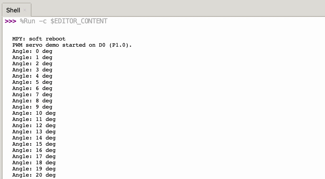
Result
After firmware flashing, the servo rotates from 0° to 180° at a speed of 33 radians per second and then rotates back to 0°.
Meanwhile, the current servo angle will be printed via USB serial port.
Analog
Analog input is based on an Analog-to-Digital Converter (ADC) and is primarily used to capture continuous analog voltage signals from external sensors. The raw digital sampling values can be mapped to actual engineering measurement values using linear or nonlinear conversion algorithms.
Hardware Preparation
| Seeed Studio XIAO nRF54LM20A Sense | Seeed Studio Grove Base for XIAO | Grove - Capacitive Soil Moisture Sensor |
|---|---|---|
|  | |
Software Preparation
According to the pinout of the XIAO nRF54LM20A Sense, D0 (P1.0, AIN0) is used as the ADC input pin. The ADC value is read and printed via the USB serial port every 500 ms.
- For the pinout of the XIAO nRF54LM20A Sense, click XIAO nRF54LM20A Pin List to view details.
"""
Read ADC on D0 (P1.0 / AIN0) and print raw value every 500 ms.
"""
import time
from boards.xiao import XiaoADC
ADC_PIN = 0 # D0 → P1.0 (AIN0)
try:
adc = XiaoADC(ADC_PIN)
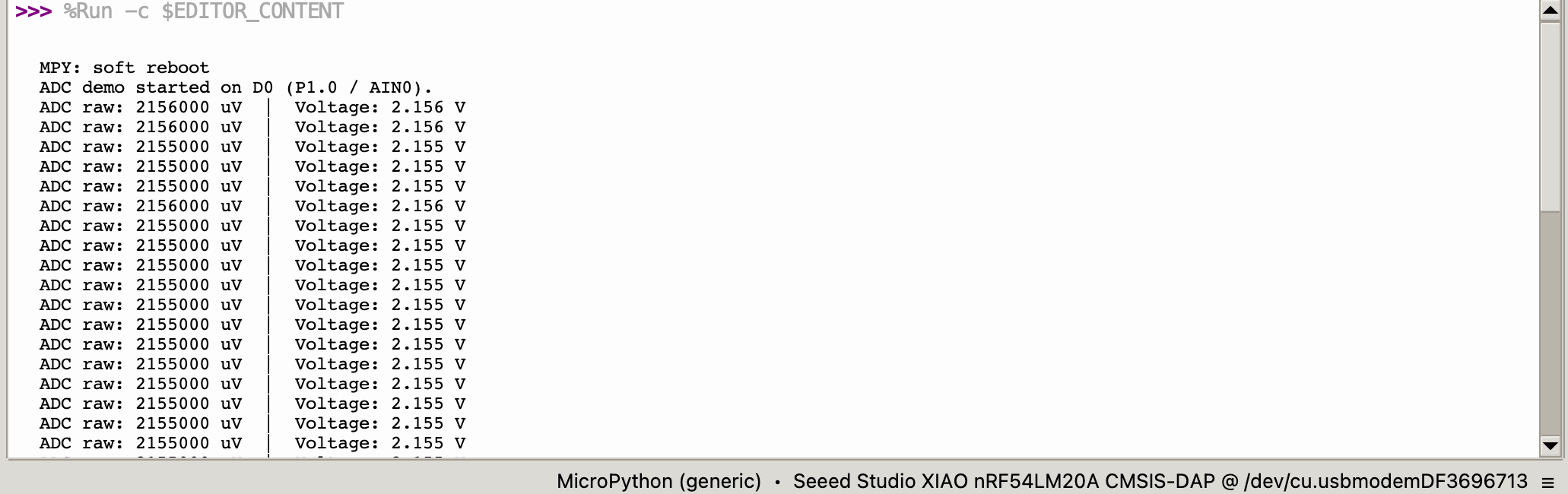
print("ADC demo started on D0 (P1.0 / AIN0).")
while True:
raw = adc.read_uv()
voltage = raw / 1_000_000.0
print("ADC raw: %d uV | Voltage: %.3f V" % (raw, voltage))
time.sleep(0.5)
except KeyboardInterrupt:
print("\nProgram interrupted by user")
except Exception as e:
print("\nError occurred: %s" % {e})
Code Explain:
- Imports:
XiaoADCfromboards.xiaoprovides ADC functionality.ADC_PIN = 0maps to D0 (P1.0 / AIN0). - Initialization:
XiaoADC(ADC_PIN)configures the pin for analog-to-digital conversion. - Main loop:
adc.read_uv()returns the ADC reading in microvolts (µV). The value is converted to volts for display. Both raw µV and voltage readings are printed every 500 ms. - Error handling:
try/except/finallyensures graceful shutdown.
Result
After flashing the program, insert the Grove-Capacitive Soil Moisture Sensor into household potted plants.
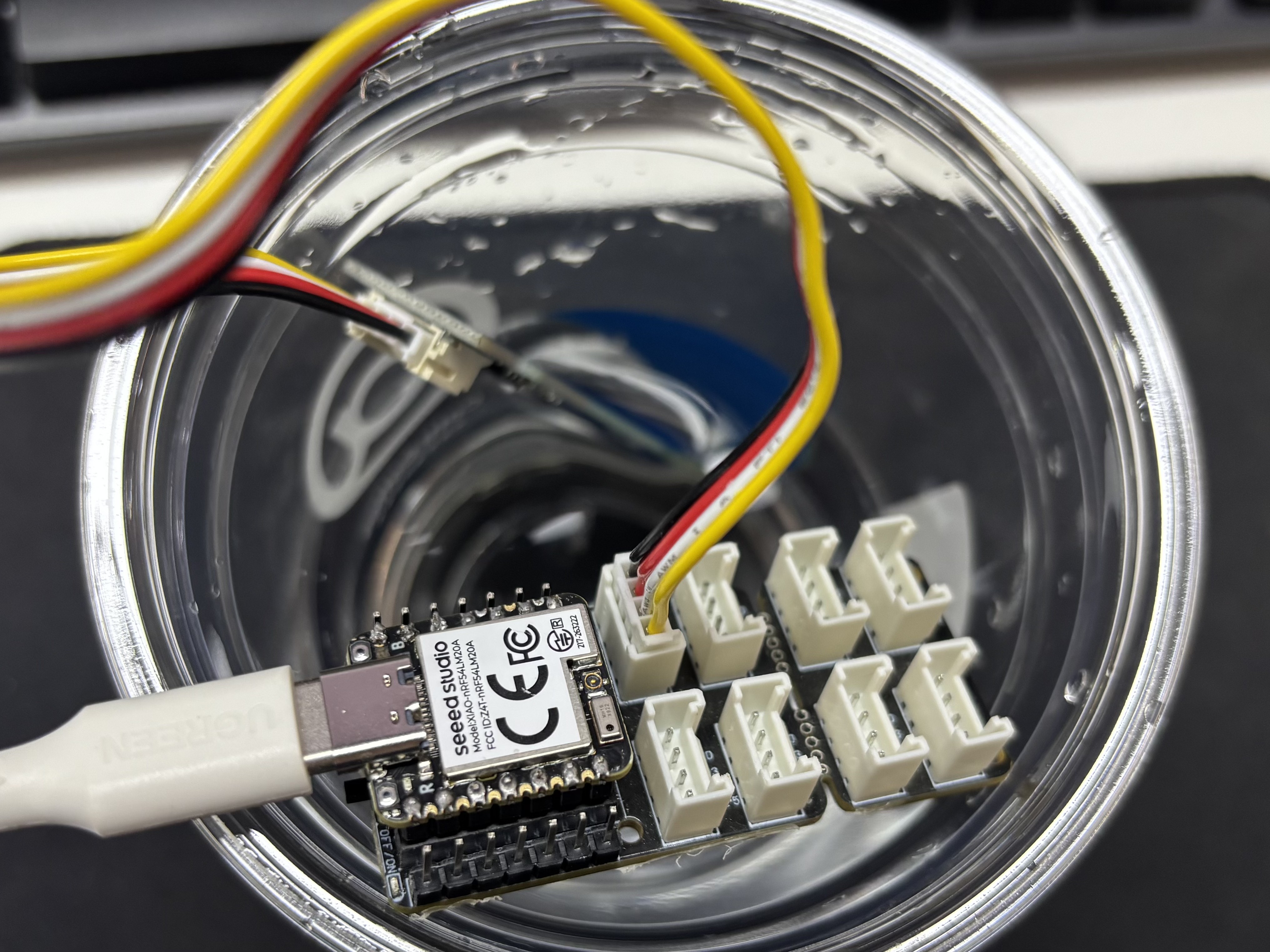
Open the serial port assistant on your computer and observe the output values.
Voltage Reference Reading Table
| Status | Sensor Output Voltage | Expected ADC Raw Value |
|---|---|---|
| In air (Dry) | ~2.0–2.4V | ~3400–4095 |
| In moist soil | ~1.3–1.8V | ~2200–3000 |
| Fully immersed in water | ~0.8–1.2V | ~1365–2048 |
Due to individual differences in components, different module measurements in the same environment may vary.
UART
Universal Asynchronous Receiver/Transmitter (UART) is a standard asynchronous serial communication protocol. It does not require external clock signals for synchronization and realizes data transmission and reception relying on the baud rate preset by both sides. A full-duplex data link can be established simply by cross-connecting the TX and RX pins.
Hardware Preparation
| Seeed Studio XIAO nRF54LM20A Sense | CH340G USB-to-Serial TTL Module Adapter |
|---|---|
 | |
Software Preparation
According to the pinout of the XIAO nRF54LM20A Sense, D6 (P1.08) and D7 (P1.09) are used as TX and RX pins for UART communication at 115200 baud.
- For the pinout of the XIAO nRF54LM20A Sense, click XIAO nRF54LM20A Pin List to view details.
import time
from machine import UART
from boards.xiao_nrf54lm20a import xiao_nrf54lm20a as xiao
uart_id = xiao.uart("uart1") # → "uart21"
uart = None
try:
uart = UART(uart_id, baudrate=115200)
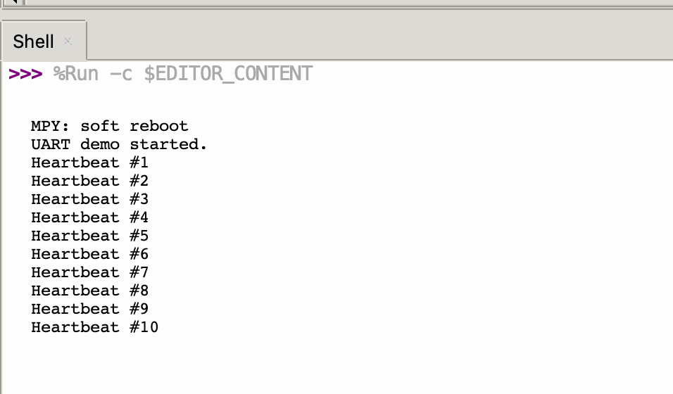
print("UART demo started.")
uart.write("========================================\r\n")
uart.write(" UART Demo for XIAO nRF54LM20A Sense\r\n")
uart.write("========================================\r\n")
uart.write("Pin Configuration:\r\n")
uart.write(" TX: D6 (P1.08)\r\n")
uart.write(" RX: D7 (P1.09)\r\n")
uart.write(" Baud Rate: 115200\r\n")
uart.write("\r\nType something and press Enter to see it echoed.\r\n\r\n")
heartbeat_count = 0
last_heartbeat = time.ticks_ms()
while True:
if uart.any():
data = uart.read()
if data:
uart.write(data)
now = time.ticks_ms()
if time.ticks_diff(now, last_heartbeat) >= 5000:
last_heartbeat = now
heartbeat_count += 1
uart.write("\r\n[Heartbeat #%d]\r\n" % heartbeat_count)
print("Heartbeat #%d" % heartbeat_count)
time.sleep_ms(10)
except KeyboardInterrupt:
print("\nStopped by user")
except Exception as e:
print("\nError: %s" % e)
finally:
if uart is not None:
uart.deinit()
Code Explain:
- Imports & pin mapping:
machine.UARTprovides hardware UART access.xiao.pin(n)returns the port and pin tuple for a given digital pin number from the board definition. - Initialization: UART 1 is configured at 115200 baud with TX on D6 (P1.08) and RX on D7 (P1.09). A welcome message is sent on startup.
- Main loop: Incoming data is echoed back. A heartbeat message is sent every 5 seconds to confirm the UART is still running.
- Cleanup:
uart.deinit()releases the UART hardware in thefinallyblock.
Result
- Wire according to the table below:
| XIAO nRF54LM20A Sense | CH340 |
|---|---|
| VBUS | 5V |
| GND | GND |
| D6 (P1.08) - TX | RX |
| D7 (P1.09) - RX | TX |
- Open the serial port monitoring software on your computer. The configured UART information is printed on startup. By default, the string
[Heartbeat #N] UART running...is printed every 5 seconds.
I2C
I2C is a synchronous, half-duplex data communication protocol. It enables multi-device connection through addressing via the SCL clock line and SDA data line, and is commonly used to read data from sensors such as IMUs and temperature/humidity sensors, or for OLED display output.
Hardware Preparation
| Seeed Studio XIAO nRF54LM20A Sense | Seeed Studio Expansion Board Base for XIAO |
|---|---|
 | |
Software Preparation
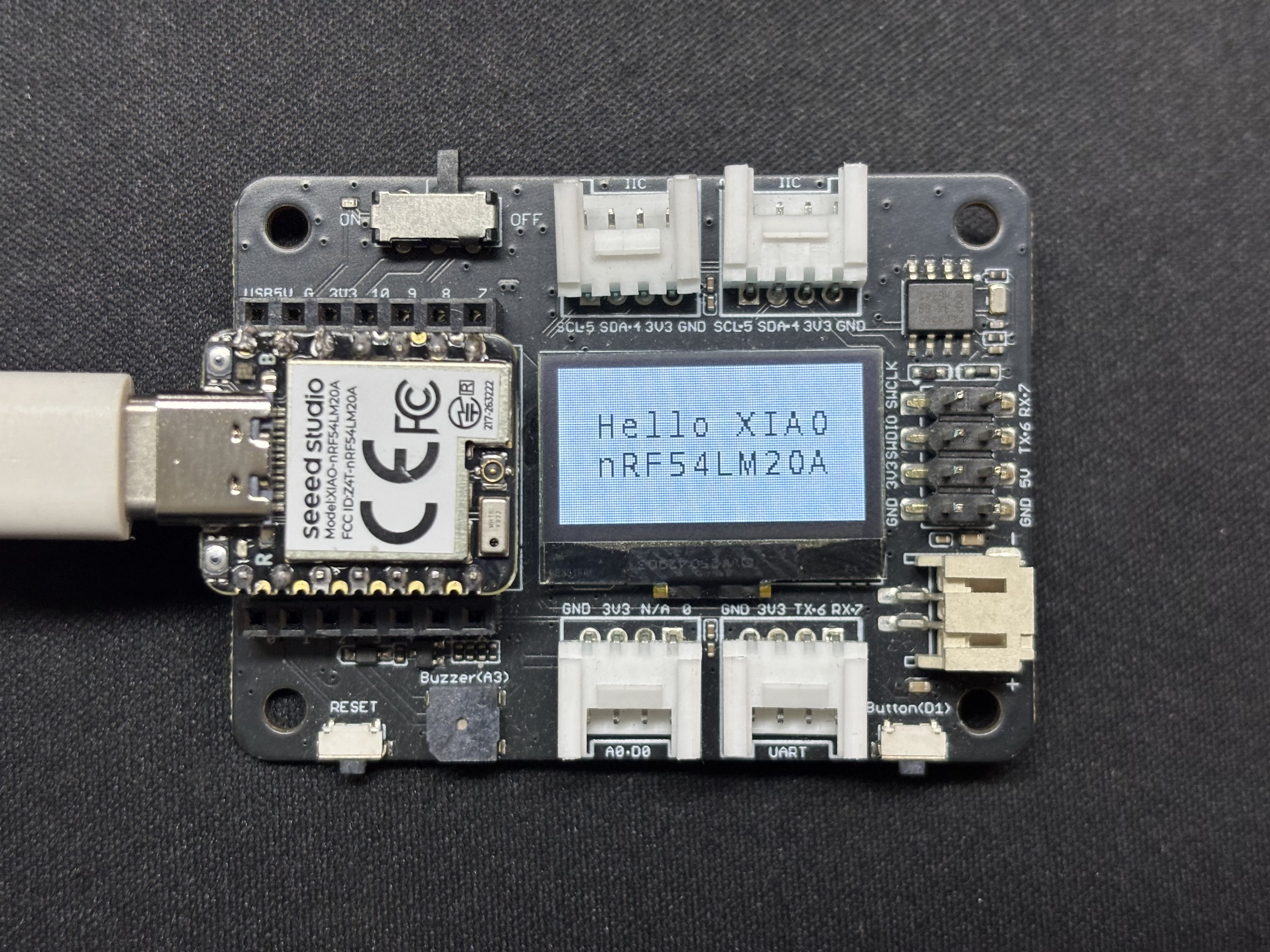
According to the pinout of the XIAO nRF54LM20A Sense, D4 (P1.03) and D5 (P1.07) are configured as I2C SDA and SCL pins respectively. This example drives an SSD1306 128×64 OLED display over I2C.
- For the pinout of the XIAO nRF54LM20A Sense, click XIAO nRF54LM20A Pin List to view details.
oled.py
"""
SSD1306 128x64 OLED display via I2C on XIAO nRF54LM20A Sense.
SDA: D4 (P1.03), SCL: D5 (P1.07)
"""

import time
from boards.xiao import XiaoI2C

SDA = 4          # D4 → P1.03
SCL = 5          # D5 → P1.07
I2C_BUS = "i2c0"
FREQ = 400_000   # 400 kHz

# --- SSD1306 I2C address and command definitions ---
SSD1306_I2C_ADDR = 0x3C
SSD1306_SET_CONTRAST = 0x81
SSD1306_DISPLAY_ALL_ON_RESUME = 0xA4
SSD1306_DISPLAY_ALL_ON = 0xA5
SSD1306_NORMAL_DISPLAY = 0xA6
SSD1306_INVERT_DISPLAY = 0xA7
SSD1306_DISPLAY_OFF = 0xAE
SSD1306_DISPLAY_ON = 0xAF
SSD1306_SET_DISPLAY_OFFSET = 0xD3
SSD1306_SET_COM_PINS = 0xDA
SSD1306_SET_VCOM_DETECT = 0xDB
SSD1306_SET_DISPLAY_CLOCK_DIV = 0xD5
SSD1306_SET_PRECHARGE = 0xD9
SSD1306_SET_MULTIPLEX = 0xA8
SSD1306_SET_LOW_COLUMN = 0x00
SSD1306_SET_HIGH_COLUMN = 0x10
SSD1306_SET_START_LINE = 0x40
SSD1306_MEMORY_MODE = 0x20
SSD1306_COLUMN_ADDR = 0x21
SSD1306_PAGE_ADDR = 0x22
SSD1306_COM_SCAN_INC = 0xC0
SSD1306_COM_SCAN_DEC = 0xC8
SSD1306_SEG_REMAP = 0xA0
SSD1306_CHARGE_PUMP = 0x8D

# Display dimensions
SSD1306_WIDTH = 128
SSD1306_HEIGHT = 64
SSD1306_PAGES = 8

# Basic 8x8 font data
font_data = {
    ' ': [0x00,0x00,0x00,0x00,0x00,0x00,0x00,0x00],
    'A': [0x18,0x24,0x42,0x7E,0x42,0x42,0x42,0x00],
    'B': [0x7C,0x42,0x42,0x7C,0x42,0x42,0x7C,0x00],
    'C': [0x3C,0x42,0x40,0x40,0x40,0x42,0x3C,0x00],
    'D': [0x78,0x44,0x42,0x42,0x42,0x44,0x78,0x00],
    'E': [0x7C,0x40,0x40,0x78,0x40,0x40,0x7C,0x00],
    'F': [0x7C,0x40,0x40,0x78,0x40,0x40,0x40,0x00],
    'G': [0x3C,0x42,0x40,0x4E,0x42,0x42,0x3C,0x00],
    'H': [0x44,0x44,0x44,0x7C,0x44,0x44,0x44,0x00],
    'I': [0x38,0x10,0x10,0x10,0x10,0x10,0x38,0x00],
    'J': [0x1C,0x08,0x08,0x08,0x08,0x48,0x30,0x00],
    'K': [0x44,0x48,0x50,0x60,0x50,0x48,0x44,0x00],
    'L': [0x40,0x40,0x40,0x40,0x40,0x40,0x7C,0x00],
    'M': [0x42,0x66,0x5A,0x42,0x42,0x42,0x42,0x00],
    'N': [0x42,0x62,0x52,0x4A,0x46,0x42,0x42,0x00],
    'O': [0x3C,0x42,0x42,0x42,0x42,0x42,0x3C,0x00],
    'P': [0x7C,0x42,0x42,0x7C,0x40,0x40,0x40,0x00],
    'Q': [0x3C,0x42,0x42,0x42,0x4A,0x44,0x3A,0x00],
    'R': [0x7C,0x42,0x42,0x7C,0x48,0x44,0x42,0x00],
    'S': [0x3C,0x42,0x40,0x3C,0x02,0x42,0x3C,0x00],
    'T': [0x7C,0x10,0x10,0x10,0x10,0x10,0x10,0x00],
    'U': [0x42,0x42,0x42,0x42,0x42,0x42,0x3C,0x00],
    'V': [0x42,0x42,0x42,0x42,0x42,0x24,0x18,0x00],
    'W': [0x42,0x42,0x42,0x42,0x5A,0x66,0x42,0x00],
    'X': [0x42,0x24,0x18,0x18,0x18,0x24,0x42,0x00],
    'Y': [0x44,0x44,0x28,0x10,0x10,0x10,0x10,0x00],
    'Z': [0x7E,0x04,0x08,0x10,0x20,0x40,0x7E,0x00],
    '0': [0x3C,0x42,0x46,0x4A,0x52,0x62,0x3C,0x00],
    '1': [0x10,0x30,0x10,0x10,0x10,0x10,0x38,0x00],
    '2': [0x3C,0x42,0x02,0x0C,0x30,0x40,0x7E,0x00],
    '3': [0x3C,0x42,0x02,0x1C,0x02,0x42,0x3C,0x00],
    '4': [0x08,0x18,0x28,0x48,0x7E,0x08,0x08,0x00],
    '5': [0x7E,0x40,0x7C,0x02,0x02,0x42,0x3C,0x00],
    '6': [0x1C,0x20,0x40,0x7C,0x42,0x42,0x3C,0x00],
    '7': [0x7E,0x42,0x04,0x08,0x10,0x10,0x10,0x00],
    '8': [0x3C,0x42,0x42,0x3C,0x42,0x42,0x3C,0x00],
    '9': [0x3C,0x42,0x42,0x3E,0x02,0x04,0x38,0x00],
    '!': [0x10,0x10,0x10,0x10,0x10,0x00,0x10,0x00],
    '?': [0x3C,0x42,0x02,0x0C,0x10,0x00,0x10,0x00],
    '.': [0x00,0x00,0x00,0x00,0x00,0x00,0x10,0x00],
    ',': [0x00,0x00,0x00,0x00,0x00,0x10,0x10,0x20],
    ':': [0x00,0x10,0x00,0x00,0x00,0x10,0x00,0x00],
    ';': [0x00,0x10,0x00,0x00,0x00,0x10,0x10,0x20],
    '-': [0x00,0x00,0x00,0x7C,0x00,0x00,0x00,0x00],
    '_': [0x00,0x00,0x00,0x00,0x00,0x00,0x7E,0x00],
    '+': [0x00,0x10,0x10,0x7C,0x10,0x10,0x00,0x00],
    '*': [0x00,0x24,0x18,0x7E,0x18,0x24,0x00,0x00],
    '/': [0x02,0x04,0x08,0x10,0x20,0x40,0x00,0x00],
    '\\': [0x40,0x20,0x10,0x08,0x04,0x02,0x00,0x00],
    '=': [0x00,0x00,0x7E,0x00,0x7E,0x00,0x00,0x00],
    '\'': [0x10,0x10,0x20,0x00,0x00,0x00,0x00,0x00],
    '"': [0x24,0x24,0x00,0x00,0x00,0x00,0x00,0x00],
    '(': [0x08,0x10,0x20,0x20,0x20,0x10,0x08,0x00],
    ')': [0x20,0x10,0x08,0x08,0x08,0x10,0x20,0x00],
    '[': [0x1C,0x10,0x10,0x10,0x10,0x10,0x1C,0x00],
    ']': [0x38,0x08,0x08,0x08,0x08,0x08,0x38,0x00],
    '{': [0x0C,0x10,0x10,0x60,0x10,0x10,0x0C,0x00],
    '}': [0x30,0x08,0x08,0x06,0x08,0x08,0x30,0x00],
    '<': [0x08,0x10,0x20,0x40,0x20,0x10,0x08,0x00],
    '>': [0x20,0x10,0x08,0x04,0x08,0x10,0x20,0x00],
    '|': [0x10,0x10,0x10,0x10,0x10,0x10,0x10,0x00],
    '@': [0x3C,0x42,0x5A,0x5A,0x5C,0x40,0x3C,0x00],
    '#': [0x24,0x24,0x7E,0x24,0x7E,0x24,0x24,0x00],
    '$': [0x10,0x3C,0x50,0x3C,0x12,0x3C,0x10,0x00],
    '%': [0x62,0x64,0x08,0x10,0x26,0x46,0x00,0x00],
    '^': [0x10,0x28,0x44,0x00,0x00,0x00,0x00,0x00],
    '&': [0x30,0x48,0x50,0x20,0x54,0x48,0x34,0x00],
    '~': [0x00,0x00,0x34,0x4C,0x00,0x00,0x00,0x00]
}

# --- Helper functions ---
def ssd1306_write_command(cmd):
    i2c.writeto(SSD1306_I2C_ADDR, bytes([0x00, cmd]))

def ssd1306_write_commands(cmds):
    data = bytearray([0x00] + list(cmds))
    i2c.writeto(SSD1306_I2C_ADDR, data)

def ssd1306_write_data(data):
    buffer = bytearray(len(data) + 1)
    buffer[0] = 0x40
    buffer[1:] = data
    i2c.writeto(SSD1306_I2C_ADDR, buffer)

def ssd1306_clear():
    ssd1306_write_commands(bytearray([SSD1306_COLUMN_ADDR, 0, SSD1306_WIDTH - 1]))
    ssd1306_write_commands(bytearray([SSD1306_PAGE_ADDR, 0, SSD1306_PAGES - 1]))
    empty_data = bytearray(SSD1306_WIDTH)
    for _ in range(SSD1306_PAGES):
        ssd1306_write_data(empty_data)
    ssd1306_write_commands([SSD1306_COLUMN_ADDR, 0, SSD1306_WIDTH - 1])

def ssd1306_init():
    commands = [
        bytearray([SSD1306_DISPLAY_OFF]),
        bytearray([SSD1306_SET_DISPLAY_CLOCK_DIV, 0x80]),
        bytearray([SSD1306_SET_MULTIPLEX, SSD1306_HEIGHT - 1]),
        bytearray([SSD1306_SET_DISPLAY_OFFSET, 0x00]),
        bytearray([SSD1306_SET_START_LINE | 0x00]),
        bytearray([SSD1306_CHARGE_PUMP, 0x14]),
        bytearray([SSD1306_MEMORY_MODE, 0x00]),
        bytearray([SSD1306_SEG_REMAP | 0x01]),
        bytearray([SSD1306_COM_SCAN_DEC]),
        bytearray([SSD1306_SET_COM_PINS, 0x12]),
        bytearray([SSD1306_SET_CONTRAST, 0xCF]),
        bytearray([SSD1306_SET_PRECHARGE, 0xF1]),
        bytearray([SSD1306_SET_VCOM_DETECT, 0x40]),
        bytearray([SSD1306_DISPLAY_ALL_ON_RESUME]),
        bytearray([SSD1306_NORMAL_DISPLAY]),
        bytearray([SSD1306_DISPLAY_ON])
    ]
    for cmd in commands:
        ssd1306_write_commands(cmd)
    ssd1306_clear()
    print("SSD1306 initialized successfully.")
    ssd1306_write_commands([SSD1306_COLUMN_ADDR, 0, SSD1306_WIDTH - 1])

def ssd1306_draw_text(text, x, y):
    ssd1306_write_commands(bytearray([SSD1306_COLUMN_ADDR, x, x + len(text) * 8 - 1]))
    ssd1306_write_commands(bytearray([SSD1306_PAGE_ADDR, y, y + 0]))
    display_data = bytearray()
    for char in text:
        font_bytes = font_data.get(char.upper(), font_data[' '])
        for col in range(7, -1, -1):
            val = 0
            for row in range(8):
                if font_bytes[row] & (1 << col):
                    val |= (1 << row)
            display_data.append(val)
    ssd1306_write_data(display_data)

try:
    i2c = XiaoI2C(I2C_BUS, SDA, SCL, FREQ)
    print("I2C initialized on %s (SDA: D%d, SCL: D%d)" % (I2C_BUS, SDA, SCL))

    i2c_addr = i2c.scan()
    if SSD1306_I2C_ADDR not in i2c_addr:
        raise Exception("SSD1306 not found on I2C bus")
    else:
        print("SSD1306 found on I2C bus: 0x{:02X}".format(SSD1306_I2C_ADDR))

    # Initialize display and draw text
    ssd1306_init()
    ssd1306_draw_text("NRF54LM20A", 22, 2)
    ssd1306_draw_text("HELLO WORLD", 20, 4)
    print("Display updated. Running...")

    while True:
        time.sleep(1)

except KeyboardInterrupt:
    print("\nProgram interrupted by user")
except Exception as e:
    print("\nError occurred: %s" % {e})
Code Explain:
- Imports & pin definitions:
XiaoI2Cfromboards.xiaoprovides I2C bus management. SDA is on D4 (P1.03) and SCL is on D5 (P1.07). The bus operates at 400 kHz. - SSD1306 driver: The SSD1306 OLED display is controlled via raw I2C command/data writes. Helper functions
ssd1306_write_command(),ssd1306_write_data(),ssd1306_clear(),ssd1306_init()andssd1306_draw_text()form a minimal driver. - Font data: An 8×8 bitmap font dictionary provides glyph definitions for printable ASCII characters. The
ssd1306_draw_text()function renders text strings by looking up glyph bitmaps and sending them to the display. - Main logic: The I2C bus is scanned to verify the SSD1306 is present at address
0x3C. The display is initialized, and two lines of centered text are drawn ("NRF54LM20A" and "HELLO WORLD"). - Cleanup: The
try/exceptblock handles graceful shutdown on keyboard interrupt or error.
Result
After the program runs, the text NRF54LM20A and HELLO WORLD will be displayed on the screen, and status information will be printed through the USB serial port.
SPI
SPI is a high-speed, synchronous and full-duplex communication protocol. It relies on a dedicated SCK clock line for data synchronization and adopts a four-wire topology consisting of MOSI, MISO, SCK, and CS/SS pins. It is widely used for driving high-resolution displays, Flash/SD card storage, and high-frequency sampling sensors.
Hardware Preparation
| Seeed Studio XIAO nRF54LM20A Sense | Round Display for Seeed Studio XIAO |
|---|---|
 | |
Software Preparation
According to the pinout of the XIAO nRF54LM20A Sense, SPI configuration uses the following pins:
| Function | Digital Pin | Physical Pin |
|---|---|---|
| SCK | D8 | P1.04 |
| MOSI | D10 | P1.06 |
| MISO | D9 | P1.05 |
| CS | D1 | P1.31 |
| DC | D3 | P1.29 |
- For the pinout of the XIAO nRF54LM20A Sense, click XIAO nRF54LM20A Pin List to view details.
import time
from machine import Pin, SPI
from boards.xiao_nrf54lm20a import xiao_nrf54lm20a as xiao

cs  = Pin(("gpio1", 31), Pin.OUT)   # D1
dc  = Pin(("gpio1", 29), Pin.OUT)   # D3
bl  = Pin(("gpio1", 8), Pin.OUT)
rst = Pin(("gpio1", 30), Pin.OUT)   # D2

spi_id = xiao.spi("spi0")
spi = SPI(spi_id, baudrate=8000000, polarity=0, phase=0)

cs.value(1)
dc.value(1)
bl.value(1)

LCD_W = 240
LCD_H = 240

def write_command(cmd):
    dc.value(0); cs.value(0)
    spi.write(bytearray([cmd & 0xFF]))
    cs.value(1)

def write_data(data):
    dc.value(1); cs.value(0)
    if isinstance(data, int):
        spi.write(bytearray([data & 0xFF]))
    else:
        spi.write(bytearray(data))
    cs.value(1)

def set_addr_window(x0, y0, x1, y1):
    dc.value(0); cs.value(0)
    spi.write(bytearray([0x2A]))
    dc.value(1)
    spi.write(bytearray([x0>>8, x0&0xFF, x1>>8, x1&0xFF]))
    cs.value(1)
    dc.value(0); cs.value(0)
    spi.write(bytearray([0x2B]))
    dc.value(1)
    spi.write(bytearray([y0>>8, y0&0xFF, y1>>8, y1&0xFF]))
    cs.value(1)
    dc.value(0); cs.value(0)
    spi.write(bytearray([0x2C]))
    cs.value(1)

def init_display():
    # Hardware reset (if reset pin is connected)
    rst.value(1)
    time.sleep_ms(10)
    rst.value(0)
    time.sleep_ms(10)
    rst.value(1)
    time.sleep_ms(120)

    # GC9A01 full initialization sequence
    write_command(0xEF)
    write_command(0xEB)
    write_data(0x14)

    write_command(0xFE)
    write_command(0xEF)

    write_command(0xEB)
    write_data(0x14)

    write_command(0x84)
    write_data(0x40)

    write_command(0x85)
    write_data(0xFF)

    write_command(0x86)
    write_data(0xFF)

    write_command(0x87)
    write_data(0xFF)

    write_command(0x88)
    write_data(0x0A)

    write_command(0x89)
    write_data(0x21)

    write_command(0x8A)
    write_data(0x00)

    write_command(0x8B)
    write_data(0x80)

    write_command(0x8C)
    write_data(0x01)

    write_command(0x8D)
    write_data(0x01)

    write_command(0x8E)
    write_data(0xFF)

    write_command(0x8F)
    write_data(0xFF)

    write_command(0xB6)
    write_data(0x00)
    write_data(0x20)

    write_command(0x36)
    write_data(0x08)  # Memory access control, adjust rotation direction as needed

    write_command(0x3A)
    write_data(0x05)  # RGB565 16-bit color mode

    write_command(0x90)
    write_data(0x08)
    write_data(0x08)
    write_data(0x08)
    write_data(0x08)

    write_command(0xBD)
    write_data(0x06)

    write_command(0xBC)
    write_data(0x00)

    write_command(0xFF)
    write_data(0x60)
    write_data(0x01)
    write_data(0x04)

    write_command(0xC3)
    write_data(0x13)
    write_command(0xC4)
    write_data(0x13)

    write_command(0xC9)
    write_data(0x22)

    write_command(0xBE)
    write_data(0x11)

    write_command(0xE1)
    write_data(0x10)
    write_data(0x0E)

    write_command(0xDF)
    write_data(0x21)
    write_data(0x0c)
    write_data(0x02)

    write_command(0xF0)
    write_data(0x45)
    write_data(0x09)
    write_data(0x08)
    write_data(0x08)
    write_data(0x26)
    write_data(0x2A)

    write_command(0xF1)
    write_data(0x43)
    write_data(0x70)
    write_data(0x72)
    write_data(0x36)
    write_data(0x37)
    write_data(0x6F)

    write_command(0xF2)
    write_data(0x45)
    write_data(0x09)
    write_data(0x08)
    write_data(0x08)
    write_data(0x26)
    write_data(0x2A)

    write_command(0xF3)
    write_data(0x43)
    write_data(0x70)
    write_data(0x72)
    write_data(0x36)
    write_data(0x37)
    write_data(0x6F)

    write_command(0xED)
    write_data(0x1B)
    write_data(0x0B)

    write_command(0xAE)
    write_data(0x77)

    write_command(0xCD)
    write_data(0x63)

    write_command(0x70)
    write_data(0x07)
    write_data(0x07)
    write_data(0x04)
    write_data(0x0E)
    write_data(0x0F)
    write_data(0x09)
    write_data(0x07)
    write_data(0x08)
    write_data(0x03)

    write_command(0xE8)
    write_data(0x34)

    write_command(0x62)
    write_data(0x18)
    write_data(0x0D)
    write_data(0x71)
    write_data(0xED)
    write_data(0x70)
    write_data(0x70)
    write_data(0x18)
    write_data(0x0F)
    write_data(0x71)
    write_data(0xEF)
    write_data(0x70)
    write_data(0x70)

    write_command(0x63)
    write_data(0x18)
    write_data(0x11)
    write_data(0x71)
    write_data(0xF1)
    write_data(0x70)
    write_data(0x70)
    write_data(0x18)
    write_data(0x13)
    write_data(0x71)
    write_data(0xF3)
    write_data(0x70)
    write_data(0x70)

    write_command(0x64)
    write_data(0x28)
    write_data(0x29)
    write_data(0xF1)
    write_data(0x01)
    write_data(0xF1)
    write_data(0x00)
    write_data(0x07)

    write_command(0x66)
    write_data(0x3C)
    write_data(0x00)
    write_data(0xCD)
    write_data(0x67)
    write_data(0x45)
    write_data(0x45)
    write_data(0x10)
    write_data(0x00)
    write_data(0x00)
    write_data(0x00)

    write_command(0x67)
    write_data(0x00)
    write_data(0x3C)
    write_data(0x00)
    write_data(0x00)
    write_data(0x00)
    write_data(0x01)
    write_data(0x54)
    write_data(0x10)
    write_data(0x32)
    write_data(0x98)

    write_command(0x74)
    write_data(0x10)
    write_data(0x85)
    write_data(0x80)
    write_data(0x00)
    write_data(0x00)
    write_data(0x4E)
    write_data(0x00)

    write_command(0x98)
    write_data(0x3e)
    write_data(0x07)

    write_command(0x35)
    write_command(0x21)

    write_command(0x11)
    time.sleep_ms(120)

    write_command(0x29)
    time.sleep_ms(120)

    bl.value(0)
    print("Seeed Studio Round Display & Backlight Active!")

def fill_screen(color):
    hi = (color >> 8) & 0xFF
    lo = color & 0xFF
    set_addr_window(0, 0, LCD_W-1, LCD_H-1)
    dc.value(1); cs.value(0)
    buf = bytearray([hi, lo] * LCD_W)
    for _ in range(LCD_H):
        spi.write(buf)
    cs.value(1)

init_display()

colors = [
    (0xF800, "RED"),
    (0x07E0, "GREEN"),
    (0x001F, "BLUE"),
    (0xFFE0, "YELLOW"),
    (0x07FF, "CYAN"),
    (0xF81F, "MAGENTA"),
    (0x0000, "BLACK"),
    (0xFFFF, "WHITE"),
]

while True:
    for color, name in colors:
        print("Solid: %s" % name)
        fill_screen(color)
        time.sleep_ms(1000)
Result
After running the program, the round display refreshes in the sequence of red, green, blue, yellow, cyan, and magenta.
Tech Support & Product Discussion
Thank you for choosing our products! We are here to provide you with different support to ensure that your experience with our products is as smooth as possible. We offer several communication channels to cater to different preferences and needs.