Usage of Built-in Sensors for XIAO nRF54LM20A Sense
The XIAO nRF54LM20A Sense is equipped with abundant on-board sensors to support multi-scenario applications. It includes the LSM6DS3TR-C six-axis sensor for posture recognition, and the MSM261DGT006 digital MEMS microphone that supports PDM digital output and omnidirectional sound pickup, which is suitable for intelligent voice scenarios. This article introduces the development and usage methods based on the rich on-board peripherals of XIAO nRF54LM20A.
- This article is developed based on the PlatformIO build system and Zephyr RTOS. If you have no prior experience with them, please refer to Getting Started With SeeedStudio XIAO nRF54LM20A
Hardware Properation
This article is developed based on the XIAO nRF54LM20A Sense, and you need to prepare the relevant hardware in advance.
| Seeed Studio XIAO nRF54LM20A Sense | 6x10 RGB WS2812 Matrix for Seeed Studio XIAO |
|---|---|
 | |
IMU
The LSM6DS3TR-C is a six-axis sensor integrating a 3-axis digital accelerometer and a 3-axis digital gyroscope, which belongs to the iNEMO inertial measurement unit (IMU) launched by STMicroelectronics. On XIAO nRF54LM20A Sense, this sensor supports interrupt-triggered data output. It features a full-scale acceleration range of ±2/±4/±8/±16 g and an angular velocity range of ±125/±250/±500/±1000/±2000 dps, and supports persistent low-power mode, making it suitable for various motion detection scenarios. The on-board chip communicates with it via the I2C protocol to acquire data.
- For more information about the LSM6DS3TR-C, please visit:Product overview for LSM6DS3TR-C and LSM6DS3TR-C Datasheet
Obtain Six-axis Data
- Modify the device tree file
app.overlayto bind the hardware pins used by LSM6DS3TR-C to the device tree. Bind IMU_SDA and IMU_SCL to the i2c30 node, corresponding to P0.08 and P0.07 on XIAO nRF54LM20A Sense. Bind the interrupt trigger pin IMU_INT1 to P0.06.
- For the pinout of the XIAO nRF54LM20A,click XIAO nRF54LM20A Sense Pin List to view details.
&pmic_i2c {
        sda-gpios = <&gpio1 18 GPIO_ACTIVE_HIGH>;
        scl-gpios = <&gpio1 17 GPIO_ACTIVE_HIGH>;
        status = "okay";
};

&pmic {
        regulators {
                imu_vdd: LDO1 {
                        regulator-min-microvolt = <3300000>;
                        regulator-max-microvolt = <3300000>;
                        regulator-boot-on;
                };
        };
};

&lsm6ds3tr_c {
        zephyr,deferred-init;
};
- Modify the prj.conf file to enable I2C and interrupt trigger configurations.
CONFIG_STDOUT_CONSOLE=y

CONFIG_LOG=y
CONFIG_LOG_BACKEND_UART=y
CONFIG_LOG_BACKEND_SHOW_COLOR=n
CONFIG_LOG_DEFAULT_LEVEL=3
CONFIG_MAIN_STACK_SIZE=2048
CONFIG_SYSTEM_WORKQUEUE_STACK_SIZE=2048
CONFIG_GPIO=y
CONFIG_I2C=y
CONFIG_MFD=y
CONFIG_REGULATOR=y
CONFIG_SENSOR=y
CONFIG_LSM6DSL=y
CONFIG_LSM6DSL_TRIGGER_GLOBAL_THREAD=y
CONFIG_CBPRINTF_FP_SUPPORT=y
CONFIG_CBPRINTF_COMPLETE=y
- Write a program to output the acquired 3-axis digital accelerometer data and 3-axis digital gyroscope data via the USB serial port.
main.c
#include <errno.h>
#include <zephyr/kernel.h>
#include <zephyr/device.h>
#include <zephyr/drivers/sensor.h>
#include <zephyr/drivers/regulator.h>
#include <zephyr/logging/log.h>

LOG_MODULE_REGISTER(zephyr_imu, LOG_LEVEL_INF);

#define IMU_NODE DT_ALIAS(imu0)

/*
 * nrf54lm20a needs power_en (fixed regulator on gpio1.12) and imu_vdd
 * (PMIC NPM1300 LDO1) enabled before the IMU can be used.
 * nrf54l15 has pdm_imu_pwr with regulator-boot-on; power is already on.
 */
#if defined(DT_N_NODELABEL_power_en)
static const struct device *const power_en_dev =
    DEVICE_DT_GET(DT_NODELABEL(power_en));
#endif

#if defined(DT_N_NODELABEL_imu_vdd)
static const struct device *const imu_vdd_dev =
    DEVICE_DT_GET(DT_NODELABEL(imu_vdd));
#endif

static int enable_imu_power(void)
{
#if defined(DT_N_NODELABEL_power_en) || defined(DT_N_NODELABEL_imu_vdd)
    int ret;
#endif

#if defined(DT_N_NODELABEL_power_en)
    if (!device_is_ready(power_en_dev)) {
        LOG_ERR("power_en regulator is not ready");
        return -ENODEV;
    }
    ret = regulator_enable(power_en_dev);
    if (ret < 0 && ret != -EALREADY) {
        LOG_ERR("Failed to enable power_en: %d", ret);
        return ret;
    }
#endif

#if defined(DT_N_NODELABEL_imu_vdd)
    if (!device_is_ready(imu_vdd_dev)) {
        LOG_ERR("imu_vdd regulator is not ready");
        return -ENODEV;
    }
    ret = regulator_enable(imu_vdd_dev);
    if (ret < 0 && ret != -EALREADY) {
        LOG_ERR("Failed to enable imu_vdd: %d", ret);
        return ret;
    }
#endif

#if defined(DT_N_NODELABEL_power_en) || defined(DT_N_NODELABEL_imu_vdd)
    /* Wait for power rail to stabilize */
    k_sleep(K_MSEC(20));
#endif

    return 0;
}

static inline float out_ev(struct sensor_value *val)
{
    return (val->val1 + (float)val->val2 / 1000000);
}

static void fetch_and_display(const struct device *dev)
{
    struct sensor_value x, y, z;
    static int trig_cnt;

    trig_cnt++;

    /* lsm6dsl accel */
    sensor_sample_fetch_chan(dev, SENSOR_CHAN_ACCEL_XYZ);
    sensor_channel_get(dev, SENSOR_CHAN_ACCEL_X, &x);
    sensor_channel_get(dev, SENSOR_CHAN_ACCEL_Y, &y);
    sensor_channel_get(dev, SENSOR_CHAN_ACCEL_Z, &z);

    LOG_INF("accel x:%f m/s^2 y:%f m/s^2 z:%f m/s^2",
            (double)out_ev(&x), (double)out_ev(&y), (double)out_ev(&z));

    /* lsm6dsl gyro */
    sensor_sample_fetch_chan(dev, SENSOR_CHAN_GYRO_XYZ);
    sensor_channel_get(dev, SENSOR_CHAN_GYRO_X, &x);
    sensor_channel_get(dev, SENSOR_CHAN_GYRO_Y, &y);
    sensor_channel_get(dev, SENSOR_CHAN_GYRO_Z, &z);

    LOG_INF("gyro x:%f rad/s y:%f rad/s z:%f rad/s",
            (double)out_ev(&x), (double)out_ev(&y), (double)out_ev(&z));

    LOG_INF("trig_cnt:%d", trig_cnt);
}

static int set_sampling_freq(const struct device *dev)
{
    int ret = 0;
    struct sensor_value odr_attr;

    /* set accel/gyro sampling frequency to 12.5 Hz */
    odr_attr.val1 = 12;
    odr_attr.val2 = 500000;

    ret = sensor_attr_set(dev, SENSOR_CHAN_ACCEL_XYZ,
            SENSOR_ATTR_SAMPLING_FREQUENCY, &odr_attr);
    if (ret != 0) {
        LOG_ERR("Cannot set sampling frequency for accelerometer.");
        return ret;
    }

    ret = sensor_attr_set(dev, SENSOR_CHAN_GYRO_XYZ,
            SENSOR_ATTR_SAMPLING_FREQUENCY, &odr_attr);
    if (ret != 0) {
        LOG_ERR("Cannot set sampling frequency for gyro.");
        return ret;
    }

    return 0;
}

#ifdef CONFIG_LSM6DSL_TRIGGER
static void trigger_handler(const struct device *dev,
                const struct sensor_trigger *trig)
{
    fetch_and_display(dev);
}

static void test_trigger_mode(const struct device *dev)
{
    struct sensor_trigger trig;

    if (set_sampling_freq(dev) != 0) {
        return;
    }

    trig.type = SENSOR_TRIG_DATA_READY;
    trig.chan = SENSOR_CHAN_ACCEL_XYZ;

    if (sensor_trigger_set(dev, &trig, trigger_handler) != 0) {
        LOG_ERR("Could not set sensor type and channel");
        return;
    }

    while (1) {
        k_sleep(K_MSEC(1000));
    }
}

#else
static void test_polling_mode(const struct device *dev)
{
    if (set_sampling_freq(dev) != 0) {
        return;
    }

    while (1) {
        fetch_and_display(dev);
        k_sleep(K_MSEC(1000));
    }
}
#endif

int main(void)
{
    const struct device *const dev = DEVICE_DT_GET(IMU_NODE);
    int ret;

    /* On nrf54lm20a, enable power_en + imu_vdd before accessing IMU.
     * On nrf54l15, these nodes don't exist; function returns immediately.
     */
    ret = enable_imu_power();
    if (ret < 0) {
        LOG_ERR("Failed to enable IMU power: %d", ret);
        return 0;
    }

    /* On nrf54lm20a, IMU has zephyr,deferred-init; must init manually.
     * On nrf54l15, device auto-inits at boot; device_is_ready() is true.
     */
    if (!device_is_ready(dev)) {
        ret = device_init(dev);
        if (ret < 0 && ret != -EALREADY) {
            LOG_ERR("Failed to initialize %s: %d", dev->name, ret);
            return 0;
        }
    }

    if (!device_is_ready(dev)) {
        LOG_ERR("%s: device not ready.", dev->name);
        return 0;
    }

#ifdef CONFIG_LSM6DSL_TRIGGER
    LOG_INF("Testing LSM6DSL sensor in trigger mode.");
    test_trigger_mode(dev);
#else
    LOG_INF("Testing LSM6DSL sensor in polling mode.");
    test_polling_mode(dev);
#endif
    return 0;
}
If you want to directly verify the performance of the IMU, clone the Platform-seeedboards repository, locate the zephyr-imu example under the examples directory, then compile and flash the program to start the test.
Result
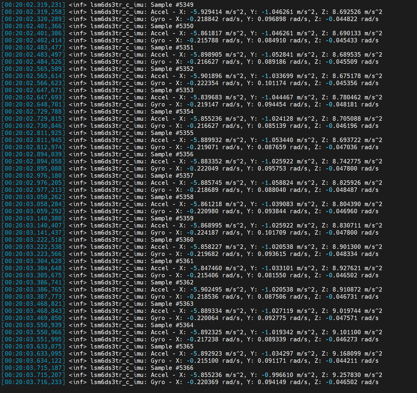
After flashing the firmware, you can open the serial port assistant on your PC for data viewing. The trigger frequency is 12.5 Hz with an interval of 80 milliseconds.
- 3-axis digital accelerometer: Measures acceleration along the X, Y, and Z axes.
- 3-axis digital gyroscope: Measures angular velocity around the X, Y, and Z axes.
- Set the baud rate to 115200 when viewing data via the serial monitor.
- Specify the baud rate as 115200 in the platformio.ini configuration file for the PlatformIO IDE serial monitor.
[env:seeed-xiao-nrf54lm20a]
platform = https://github.com/Seeed-Studio/platform-seeedboards.git
framework = zephyr
board = seeed-xiao-nrf54lm20a
monitor_speed = 115200
Application
The IMU can fuse three-axis acceleration data to calculate pitch, yaw and roll attitude angles for posture recognition. It can also work with corresponding controllers to realize motion control, or be applied in low-power scenarios such as attitude-triggered wake-up.
Electronic Ocean
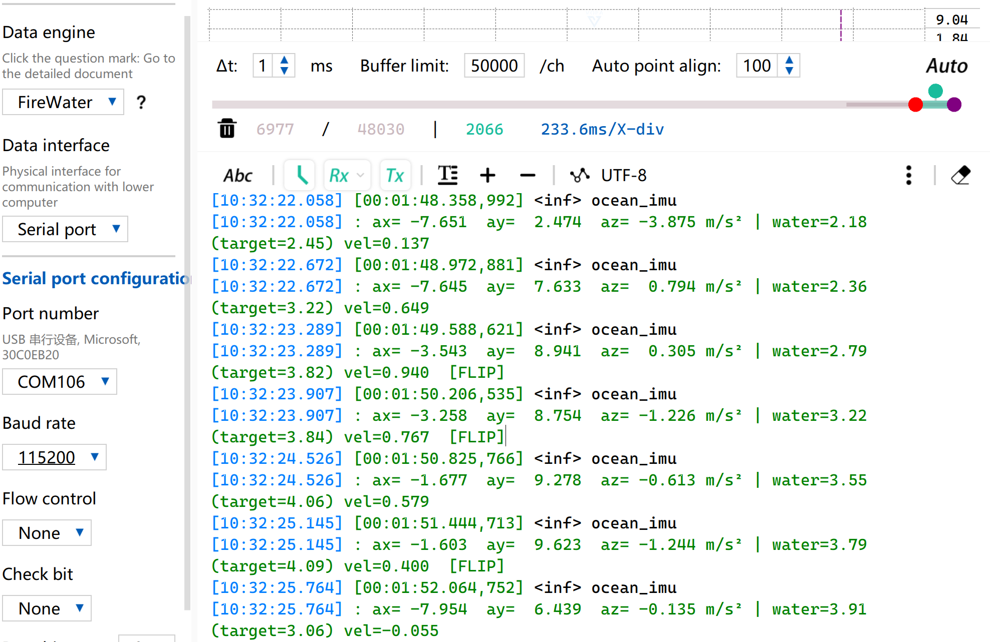
This is an example based on the on-board IMU of XIAO nRF54LM20A Sense. It collects attitude data and fuses acceleration information to map motion states onto the RGB light panel, achieving visual ocean rhythm effects.
- Tilt Water Level Control — Adjust water level height via left and right roll tilt
- Wave Animation — Three-layer frequency superimposed wave surface, 2D wave propagation and edge reflection effect
- Fluid Inertia — Water surface with momentum; rapid tilt causes overshoot and subsequent sloshing rebound
- Flip Detection — The display automatically mirrors when the board is flipped
- Dynamic Color — Random gradient ocean tone switching for each column
In addition, you can modify the RGB array configuration of the board through macro definitions in main.c.
#define COLS 10          // Number of matrix columns
#define ROWS  6          // Number of matrix rows
#define BRIGHTNESS 5     // Overall brightness (0-100)
#define WATER_CENTER 3.5f // Water level when placed horizontally
#define WATER_MIN 0.5f   // Minimum water level
#define WATER_MAX 6.5f   // Maximum water level
Usage Instructions
-
Copy the contents of the corresponding program imu_ocean-main.c and paste it into main.c.
-
Modify the device tree file
app.overlay.
&lsm6ds3tr_c {
	zephyr,deferred-init;
};

/*
 * The board DTS lists PMIC I2C on gpio1.15/16, but the actual XIAO
 * nRF54LM20A Sense hardware uses gpio1.18 (SDA) and gpio1.17 (SCL).
 * Override here to match the working reference example.
 */
&pmic_i2c {
	sda-gpios = <&gpio1 18 GPIO_ACTIVE_HIGH>;
	scl-gpios = <&gpio1 17 GPIO_ACTIVE_HIGH>;
};

/*
 * Give LDO1 the label "imu_vdd" so main() can call regulator_enable().
 * Voltage is 3.3 V as used by the reference example.
 */
&pmic {
	regulators {
		imu_vdd: LDO1 {
			regulator-min-microvolt = <3300000>;
			regulator-max-microvolt = <3300000>;
			regulator-boot-on;
		};
	};
};

/* WS2812 LED strip on SPI24 (spi21/22 conflict with uart21/i2c22) */
&pinctrl {
	spi24_ws2812_default: spi24_ws2812_default {
		group1 {
			psels = <NRF_PSEL(SPIM_MOSI, 1, 0)>,
				<NRF_PSEL(SPIM_SCK, 1, 1)>;
		};
	};

	spi24_ws2812_sleep: spi24_ws2812_sleep {
		group1 {
			psels = <NRF_PSEL(SPIM_MOSI, 1, 0)>,
				<NRF_PSEL(SPIM_SCK, 1, 1)>;
			low-power-enable;
		};
	};
};


&spi24 {
	status = "okay";
	pinctrl-0 = <&spi24_ws2812_default>;
	pinctrl-1 = <&spi24_ws2812_sleep>;
	pinctrl-names = "default", "sleep";

	led_strip: ws2812@0 {
		compatible = "worldsemi,ws2812-spi";
		reg = <0>;
		/*
		 * 8 MHz SPI: each clock = 125 ns, 8 clocks = 1 µs per WS2812 bit.
		 * 0xF8 = 11111000: T1H=625 ns  T1L=375 ns
		 * 0xC0 = 11000000: T0H=250 ns  T0L=750 ns
		 */
		spi-max-frequency = <8000000>;
		spi-one-frame  = <0xF8>;
		spi-zero-frame = <0xC0>;
		chain-length = <60>;
		color-mapping = <1 0 2>;
		reset-delay = <250>;
	};
};

/ {
	aliases {
		led-strip = &led_strip;
	};
};
- Enable configurations related to IMU usage
CONFIG_STDOUT_CONSOLE=y
CONFIG_LOG=y
CONFIG_LOG_BACKEND_UART=y
CONFIG_LOG_DEFAULT_LEVEL=3
CONFIG_MAIN_STACK_SIZE=4096
CONFIG_SYSTEM_WORKQUEUE_STACK_SIZE=2048
CONFIG_GPIO=y
CONFIG_I2C=y
CONFIG_MFD=y
CONFIG_REGULATOR=y
CONFIG_SENSOR=y
CONFIG_LSM6DSL=y
CONFIG_SPI=y
CONFIG_LED_STRIP=y
CONFIG_WS2812_STRIP_SPI=y
CONFIG_CBPRINTF_FP_SUPPORT=y
CONFIG_CBPRINTF_COMPLETE=y
CONFIG_FAULT_DUMP=2
CONFIG_LOG_MODE_IMMEDIATE=y
- Shake the device to trigger the ocean wave visual effect.
- Meanwhile, the serial port will also output corresponding IMU data and the current water level height of the waves.
IMU Wake-Up
In this routine, the green channel of RGB lights up and turns off after power-on, then the system enters ultra-low power sleep mode. When a tap is detected by the board, XIAO nRF54LM20A Sense will be woken up via interrupt. The tap event will be recorded and printed through the serial port.
Download the routine to implement IMU wake-up function.
-
Download the imu-click-main.c program and replace the contents of main.c with it.
-
Modify the device tree file
app.overlayand add the required node configurations.
/*
 * Disable PWM20 and PWM LEDs to release P1.22/23/24 as GPIO.
 * The board DTS assigns these pins to PWM_OUT0/1/2 via pinctrl,
 * which prevents gpio-leds from controlling them.
 */
&pwm20 {
	status = "disabled";
};

&green_led {
	gpios = <&gpio1 24 GPIO_ACTIVE_LOW>;
};

/* PMIC I2C pin configuration for NPM1300 power management */
&pmic_i2c {
	sda-gpios = <&gpio1 18 GPIO_ACTIVE_HIGH>;
	scl-gpios = <&gpio1 17 GPIO_ACTIVE_HIGH>;
	status = "okay";
};

/* IMU power rail via PMIC LDO1 at 3.3V */
&pmic {
	regulators {
		imu_vdd: LDO1 {
			regulator-min-microvolt = <3300000>;
			regulator-max-microvolt = <3300000>;
			regulator-boot-on;
		};
	};
};

/* Configure I2C30 for LSM6DS3TR-C */
&i2c30 {
	pinctrl-0 = <&i2c30_default>;
	pinctrl-1 = <&i2c30_sleep>;
	pinctrl-names = "default", "sleep";
	status = "okay";
	clock-frequency = <I2C_BITRATE_STANDARD>;

	lsm6ds3tr_c: lsm6ds3tr-c@6a {
		compatible = "st,lsm6dsl";
		reg = <0x6a>;
		irq-gpios = <&gpio0 6 GPIO_ACTIVE_HIGH>;
		status = "okay";
		zephyr,deferred-init;
	};
};

/* Pin control configuration for I2C30 */
&pinctrl {
	i2c30_default: i2c30_default {
		group1 {
			psels = <NRF_PSEL(TWIM_SDA, 0, 8)>,
				<NRF_PSEL(TWIM_SCL, 0, 7)>;
		};
	};

	i2c30_sleep: i2c30_sleep {
		group1 {
			psels = <NRF_PSEL(TWIM_SDA, 0, 8)>,
				<NRF_PSEL(TWIM_SCL, 0, 7)>;
			low-power-enable;
		};
	};
};
- Enable relevant IMU configurations in prj.conf
CONFIG_STDOUT_CONSOLE=y
CONFIG_LOG=y
CONFIG_LOG_BACKEND_UART=y
CONFIG_LOG_DEFAULT_LEVEL=3
CONFIG_MAIN_STACK_SIZE=4096
CONFIG_SYSTEM_WORKQUEUE_STACK_SIZE=2048
CONFIG_GPIO=y
CONFIG_I2C=y
CONFIG_MFD=y
CONFIG_REGULATOR=y
CONFIG_SENSOR=y
CONFIG_LSM6DSL=y
CONFIG_LSM6DSL_TRIGGER_GLOBAL_THREAD=y
CONFIG_SPI=y
CONFIG_LED_STRIP=y
CONFIG_WS2812_STRIP_SPI=y
CONFIG_CBPRINTF_FP_SUPPORT=y
CONFIG_CBPRINTF_COMPLETE=y
CONFIG_FAULT_DUMP=2
CONFIG_LOG_MODE_IMMEDIATE=y
- After flashing and powering on, the RGB-G LED will flash briefly. Tap anywhere on the board to turn on the RGB-G LED.
- Meanwhile, tap event information will also be output via the serial port.
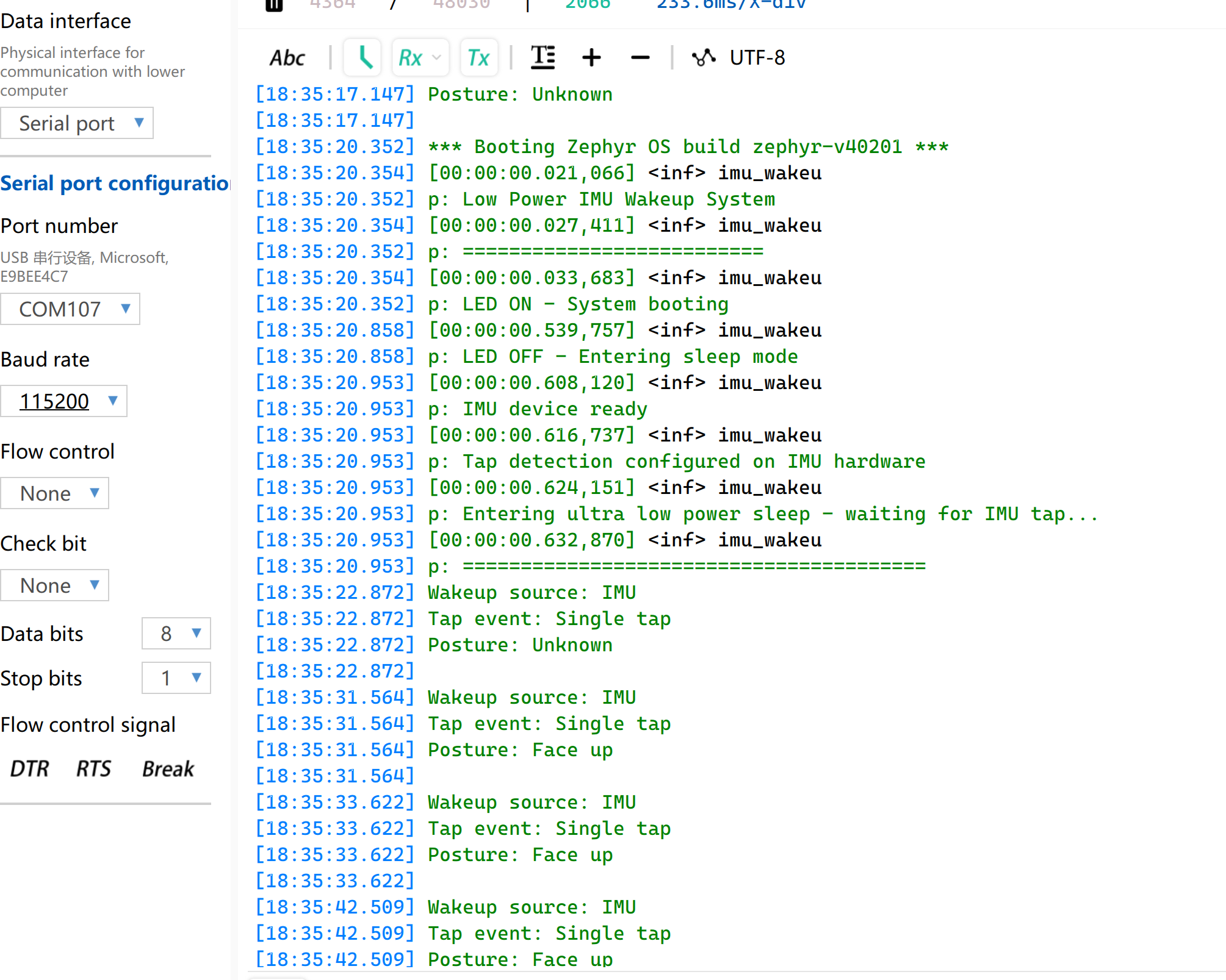
The sensing position is for reference only. Accurate tap position recognition depends on the IMU fusion control algorithm.
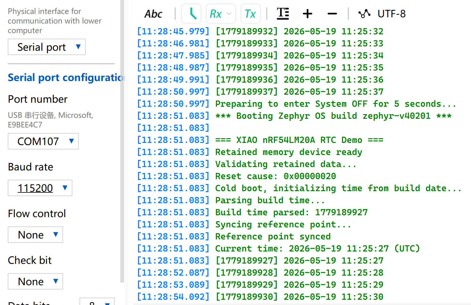
RTC
The chip adopted by XIAO nRF54LM20A Sense is equipped with built-in GRTC hardware resources, enabling RTC functions without additional RTC modules.
The RTC supports timestamp counting and can record operating time even after power failure, which facilitates log recording and time tracking.
This section introduces a sample program implemented on XIAO nRF54LM20A Sense. After power-on, it obtains timestamps starting from the compilation time via RTC and prints data every second. After entering System OFF mode, the system will be woken up by the RTC alarm to continue counting.
-
Copy rtc-main.c into the main.c file. Use the RTC functions to print the timestamp.
-
Modify the device tree
app.overlayto enable the RTC node.
/ {
    cpuapp_sram@2007ec00 {
        compatible = "zephyr,memory-region", "mmio-sram";
        reg = <0x2007ec00 DT_SIZE_K(4)>;
        zephyr,memory-region = "RetainedMem";
        status = "okay";

        retainedmem0: retainedmem {
            compatible = "zephyr,retained-ram";
            status = "okay";
        };
    };

    aliases {
        retainedmemdevice = &retainedmem0;
    };
};

&cpuapp_sram {
    /* Shrink SRAM to avoid overlap with retained memory region:
     * 511 - 4 = 507 KB = 0x7EC00
     */
    reg = <0x20000000 DT_SIZE_K(507)>;
    ranges = <0x0 0x20000000 0x7ec00>;
};
- Edit the prj.conf file to enable relevant RTC configurations.
# Console and serial
CONFIG_SERIAL=y
CONFIG_CONSOLE=y
CONFIG_PRINTK=y

# Power management and System OFF
CONFIG_PM=y
CONFIG_PM_DEVICE=y
CONFIG_POWEROFF=y

# Hardware info (reset cause detection)
CONFIG_HWINFO=y

# Retained memory (survives System OFF)
CONFIG_RETAINED_MEM=y

# CRC for retained data validation
CONFIG_CRC=y

# Newlib C library (required for sscanf, strcmp etc.)
# Note: mktime() and gmtime() are NOT used — custom tm_to_unix()
# and unix_to_tm() avoid newlib's TZ environment dependency.
CONFIG_NEWLIB_LIBC=y
Result
- The program starts counting from the time of compilation and flashing. Open the serial port tool to observe the running effect, and all expected functions are implemented.
MIC
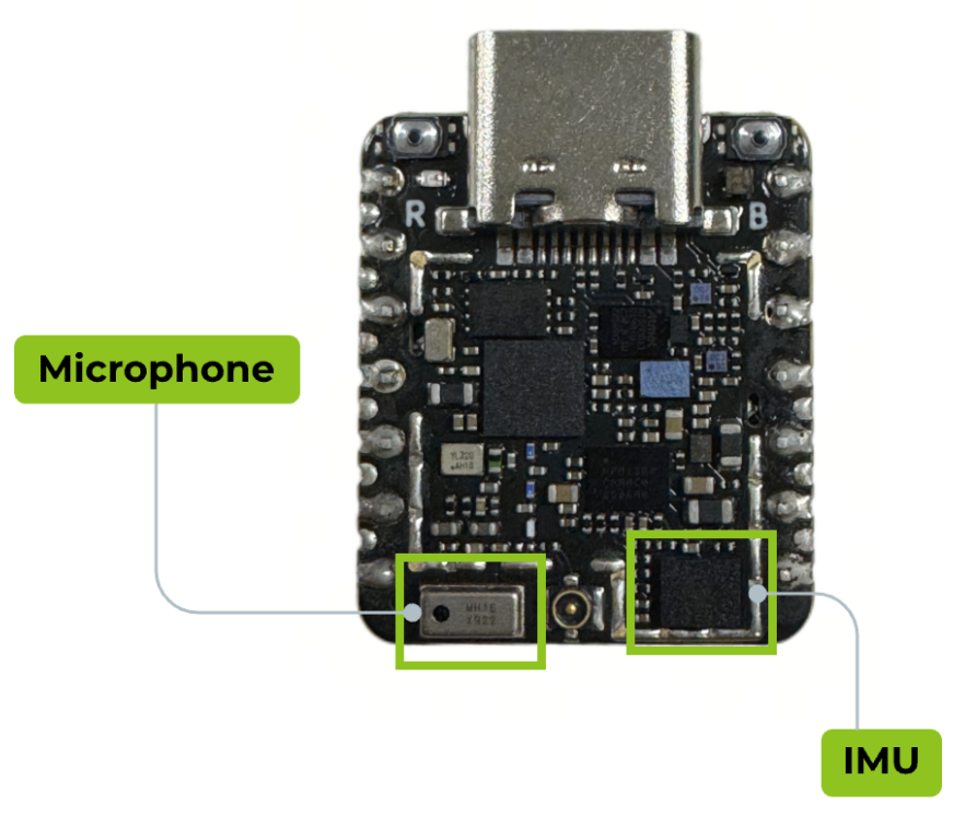
The XIAO nRF54LM20A Sense is equipped with the MSM261DGT006 digital MEMS microphone for voice input. It connects directly via the PDM interface without requiring an ADC. It is suitable for wearable devices, smart devices, voice recognition, audio recording and other application scenarios that require acoustic sensing functions.
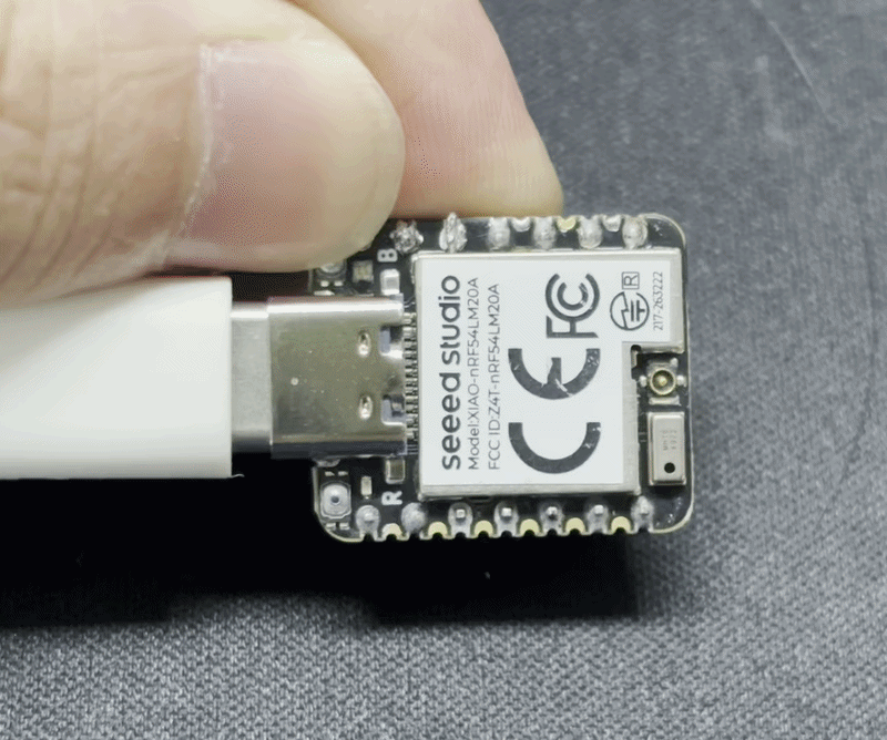
Among the XIAO nRF54LM20A series, only the XIAO nRF54M20A Sense is equipped with a microphone, which is located at the bottom-left corner of the development board.
Audio Recording and BLE Upload
This section demonstrates the microphone function through a voice example. The specific process is as follows:
- Press the BOOT button, the RGB-G LED will stay on and start recording; press it again to stop recording (maximum 10 seconds).
- After recording, the audio file will be sent to the host computer via Bluetooth. The RGB-G LED flashes during transmission.
- Run the receiving script on Windows to save the audio file to the desktop.
- The RGB-G LED turns off after the transmission is completed.
-
Copy the program from mic-main.c into
main.c. -
Modify the device tree file
app.overlayto bind the BLE node.
dmic_dev: &pdm20 {
	status = "okay";
};

/* Disable Nordic SoftDevice Controller (not available in mainline Zephyr) */
&bt_hci_sdc {
	status = "disabled";
};

/* Enable Zephyr native BLE controller (LL SW Split) */
&bt_hci_controller {
	status = "okay";
};

&pwm20 {
	status = "disabled";
};

&pmic_i2c {
	sda-gpios = <&gpio1 18 GPIO_ACTIVE_HIGH>;
	scl-gpios = <&gpio1 17 GPIO_ACTIVE_HIGH>;
	status = "okay";
};

&pmic {
	regulators {
		dmic_vdd: LDO1 {
			regulator-min-microvolt = <3300000>;
			regulator-max-microvolt = <3300000>;
			regulator-boot-on;
		};
	};
};

&uart20 {
	current-speed = <921600>;
};

/ {
	chosen {
		zephyr,bt-hci = &bt_hci_controller;
	};

	leds {
		compatible = "gpio-leds";
		led2: led_2 {
			gpios = <&gpio1 24 GPIO_ACTIVE_LOW>;
		};
	};
};

/* External 8MB SPI NOR Flash for audio storage */
&py25q64 {
	status = "okay";
};
- Modify the
prj.conffile to enable configurations for Bluetooth and microphone, and set the Bluetooth device name to XIAO MIC.
# Audio / DMIC
CONFIG_AUDIO=y
CONFIG_AUDIO_DMIC=y

# GPIO
CONFIG_GPIO=y

# I2C / PMIC
CONFIG_I2C=y
CONFIG_MFD=y
CONFIG_REGULATOR=y

# Logging
CONFIG_LOG=y

# UART for console logging
CONFIG_SERIAL=y
CONFIG_UART_ASYNC_API=y
CONFIG_UART_20_ASYNC=y
CONFIG_UART_21_ASYNC=y
CONFIG_UART_NRFX_UARTE_ENHANCED_RX=y

# BLE
CONFIG_BT=y
CONFIG_BT_PERIPHERAL=y
CONFIG_BT_DEVICE_NAME="XIAO-MIC"
CONFIG_BT_DEVICE_APPEARANCE=833
CONFIG_BT_MAX_CONN=1
CONFIG_BT_MAX_PAIRED=1

# BLE log level: ERR only.  Fixed 30 ms application pacing prevents
# buffer exhaustion; this just silences WRN/INF noise from the stack.
CONFIG_BT_LOG_LEVEL_ERR=y

# Disable auto-procedures to avoid LL Procedure Collision (reason 35)
# on nRF54L with Zephyr native BLE controller
CONFIG_BT_AUTO_PHY_UPDATE=n
CONFIG_BT_GAP_AUTO_UPDATE_CONN_PARAMS=n
CONFIG_BT_CTLR_CONN_PARAM_REQ=n

# Disable data length auto-update (can also cause LL races)
CONFIG_BT_DATA_LEN_UPDATE=n

# BLE buffer tuning for high-throughput NUS notifications
# nRF54LM20A has 1.5MB RAM, generous buffer allocation
CONFIG_BT_BUF_ACL_TX_SIZE=251
CONFIG_BT_BUF_ACL_TX_COUNT=32
CONFIG_BT_BUF_EVT_RX_COUNT=33
CONFIG_BT_BUF_ACL_RX_SIZE=251
CONFIG_BT_L2CAP_TX_MTU=247
CONFIG_BT_L2CAP_TX_BUF_COUNT=24
CONFIG_BT_L2CAP_TX_FRAG_COUNT=12
CONFIG_BT_ATT_TX_COUNT=24
CONFIG_BT_CONN_TX_MAX=32

# Note: BT_CTLR_DATA_LENGTH is selected indirectly (e.g. by BT_DATA_LEN_UPDATE).
# It cannot be set directly, so BT_CTLR_DATA_LENGTH_MAX is also omitted.

# BLE NUS
CONFIG_BT_ZEPHYR_NUS=y
CONFIG_BT_ZEPHYR_NUS_DEFAULT_INSTANCE=y

# Memory
CONFIG_HEAP_MEM_POOL_SIZE=16384

# System workqueue stack (increased for BLE work items)
CONFIG_SYSTEM_WORKQUEUE_STACK_SIZE=4096

# External SPI NOR Flash (8MB PY25Q64HA)
CONFIG_SPI=y
CONFIG_SPI_NOR=y
CONFIG_FLASH=y
CONFIG_FLASH_PAGE_LAYOUT=y

# Assert level
CONFIG_ASSERT=y
CONFIG_BT_CTLR_ASSERT_OPTIMIZE_FOR_SIZE=n
Result
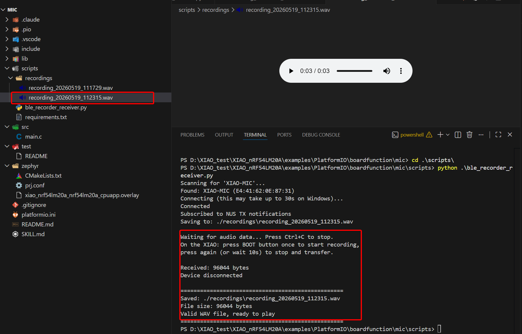
Compile and flash the program, then use a Windows computer to receive recorded audio via Bluetooth with the help of scripts.
- Run the Python script
Install required dependent libraries before execution:
pip install bleak
Copy the Python script file.
ble_recorder_receiver.py
"""
BLE Audio Receiver for XIAO nRF54LM20A BLE Audio Recorder

Connects to "XIAO-MIC" via BLE, subscribes to Nordic UART Service (NUS)
notifications, receives WAV audio data, and saves it to a file.

Requirements: pip install bleak

Usage: python ble_recorder_receiver.py
"""

import asyncio
import sys
import os
from datetime import datetime

from bleak import BleakScanner, BleakClient, BleakError

# Nordic UART Service (NUS) UUIDs
NUS_SERVICE_UUID = "6E400001-B5A3-F393-E0A9-E50E24DCCA9E"
NUS_TX_CHAR_UUID = "6E400003-B5A3-F393-E0A9-E50E24DCCA9E"  # Notify (device -> host)

DEVICE_NAME = "XIAO-MIC"
OUTPUT_DIR = "./recordings"


def make_output_path():
    os.makedirs(OUTPUT_DIR, exist_ok=True)
    timestamp = datetime.now().strftime("%Y%m%d_%H%M%S")
    return os.path.join(OUTPUT_DIR, f"recording_{timestamp}.wav")


async def main():
    output_path = make_output_path()
    total_bytes = 0
    transfer_complete = asyncio.Event()
    connected = False

    def notification_handler(sender, data):
        nonlocal total_bytes
        with open(output_path, "ab") as f:
            f.write(data)
        total_bytes += len(data)
        sys.stdout.write(f"\rReceived: {total_bytes} bytes")
        sys.stdout.flush()

    def disconnected_callback(client):
        nonlocal connected
        connected = False
        print("\nDevice disconnected")
        transfer_complete.set()

    client = None
    try:
        # Step 1: scan with active scanning (find_device_by_name does active scan)
        print(f"Scanning for '{DEVICE_NAME}'...")
        device = await BleakScanner.find_device_by_name(
            DEVICE_NAME, timeout=10.0,
        )

        if device is None:
            print(f"Device '{DEVICE_NAME}' not found. Check:")
            print("  1. XIAO is powered on")
            print("  2. PC Bluetooth is enabled")
            sys.exit(1)

        print(f"Found: {device.name} ({device.address})")

        # Step 2: connect with service UUID filtering
        # By specifying the NUS service UUID, we help Windows discover only what we need
        print("Connecting (this may take up to 30s on Windows)...")

        client = BleakClient(
            device.address,
            disconnected_callback=disconnected_callback,
            timeout=30.0,
            services=[NUS_SERVICE_UUID],
        )
        await client.connect()
        connected = True
        print("Connected")

        # Step 3: subscribe to notifications
        await client.start_notify(NUS_TX_CHAR_UUID, notification_handler)
        print("Subscribed to NUS TX notifications")
        print(f"Saving to: {output_path}")
        print()
        print("Waiting for audio data... Press Ctrl+C to stop.")
        print("On the XIAO: press BOOT button once to start recording,")
        print("press again (or wait 10s) to stop and transfer.\n")

        try:
            await asyncio.wait_for(
                transfer_complete.wait(),
                timeout=600.0,
            )
        except asyncio.TimeoutError:
            print("\nTimeout: no activity for 10 minutes")
        except KeyboardInterrupt:
            print("\nStopped by user")

    except (BleakError, asyncio.TimeoutError) as e:
        print(f"\nBLE error: {e}")
        print()
        print("Windows BLE workarounds:")
        print("  1. Windows Settings > Bluetooth & devices > Devices")
        print("     Remove 'XIAO-MIC' if listed")
        print("  2. Toggle Bluetooth OFF then ON")
        print("  3. Reset XIAO board (replug USB)")
        print("  4. Reboot PC if all else fails")
        sys.exit(1)
    finally:
        if client and connected:
            try:
                await client.stop_notify(NUS_TX_CHAR_UUID)
                await client.disconnect()
            except Exception:
                pass

    file_size = os.path.getsize(output_path) if os.path.exists(output_path) else 0
    print(f"\n{'='*50}")
    print(f"Saved: {output_path}")
    print(f"File size: {file_size} bytes")
    if file_size > 44:
        print("Valid WAV file, ready to play")
    elif file_size > 0:
        print("File may be incomplete (header only)")
    else:
        print("No data received")
    print(f"{'='*50}")


if __name__ == "__main__":
    asyncio.run(main())
Script execution command:
python ble_recorder_receiver.py
The BLE UUID is already configured in the Python program, so it will connect automatically after running the script.
- Check the Result
- Press the BOOT key to start recording. The steady green RGB LED indicates recording is in progress. You can speak loudly towards the microphone, then press the BOOT key again to stop recording. The flashing green RGB LED means the audio file is being transmitted.
- Open the Serial port, it will be print log.Please set the Baud rate for 921600.
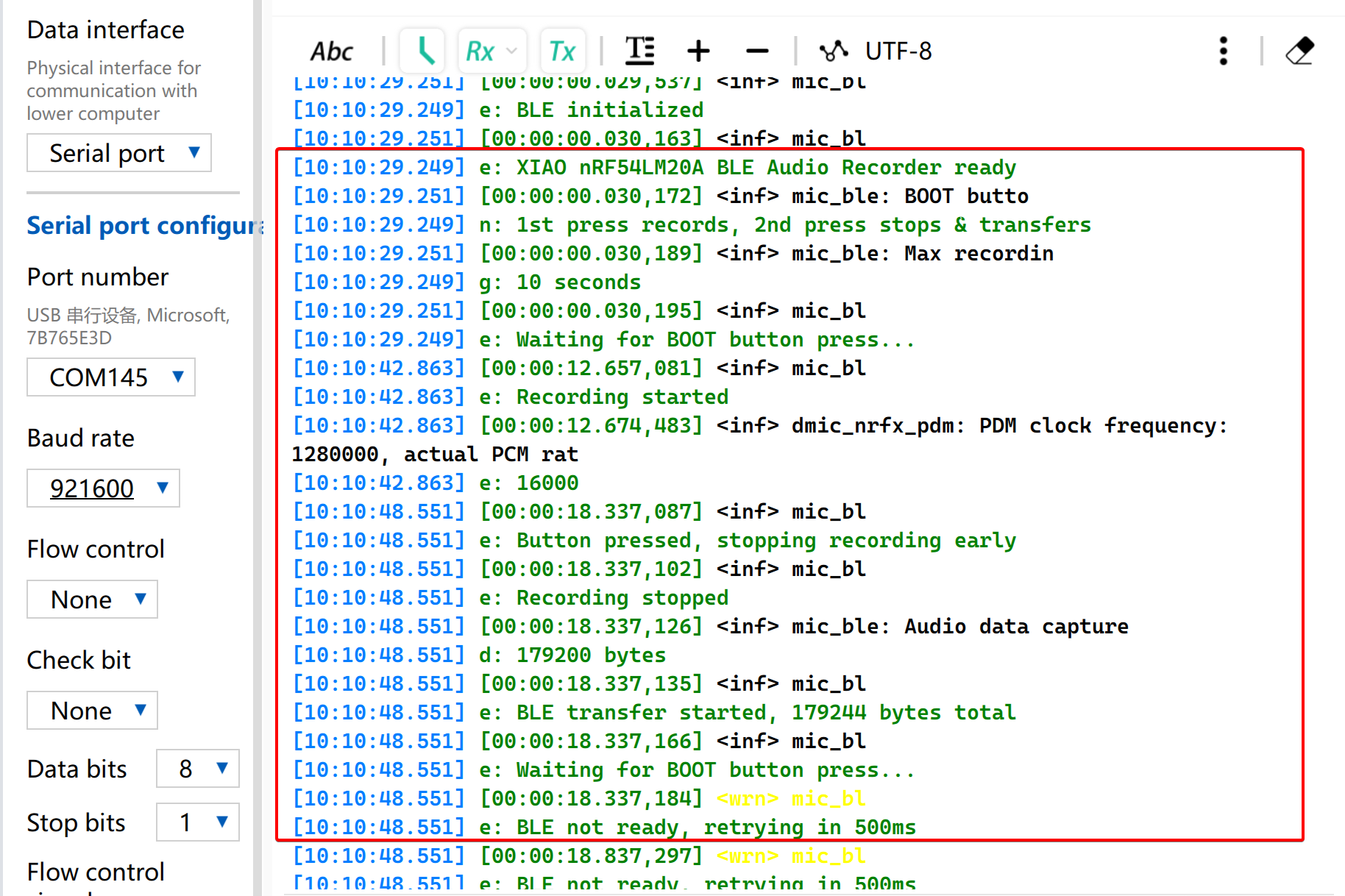
- The received audio file and its byte size will be displayed.
Tech Support & Product Discussion
Thank you for choosing our products! We are here to provide you with different support to ensure that your experience with our products is as smooth as possible. We offer several communication channels to cater to different preferences and needs.