Pin Multiplexing with Seeed Studio XIAO RA4M1
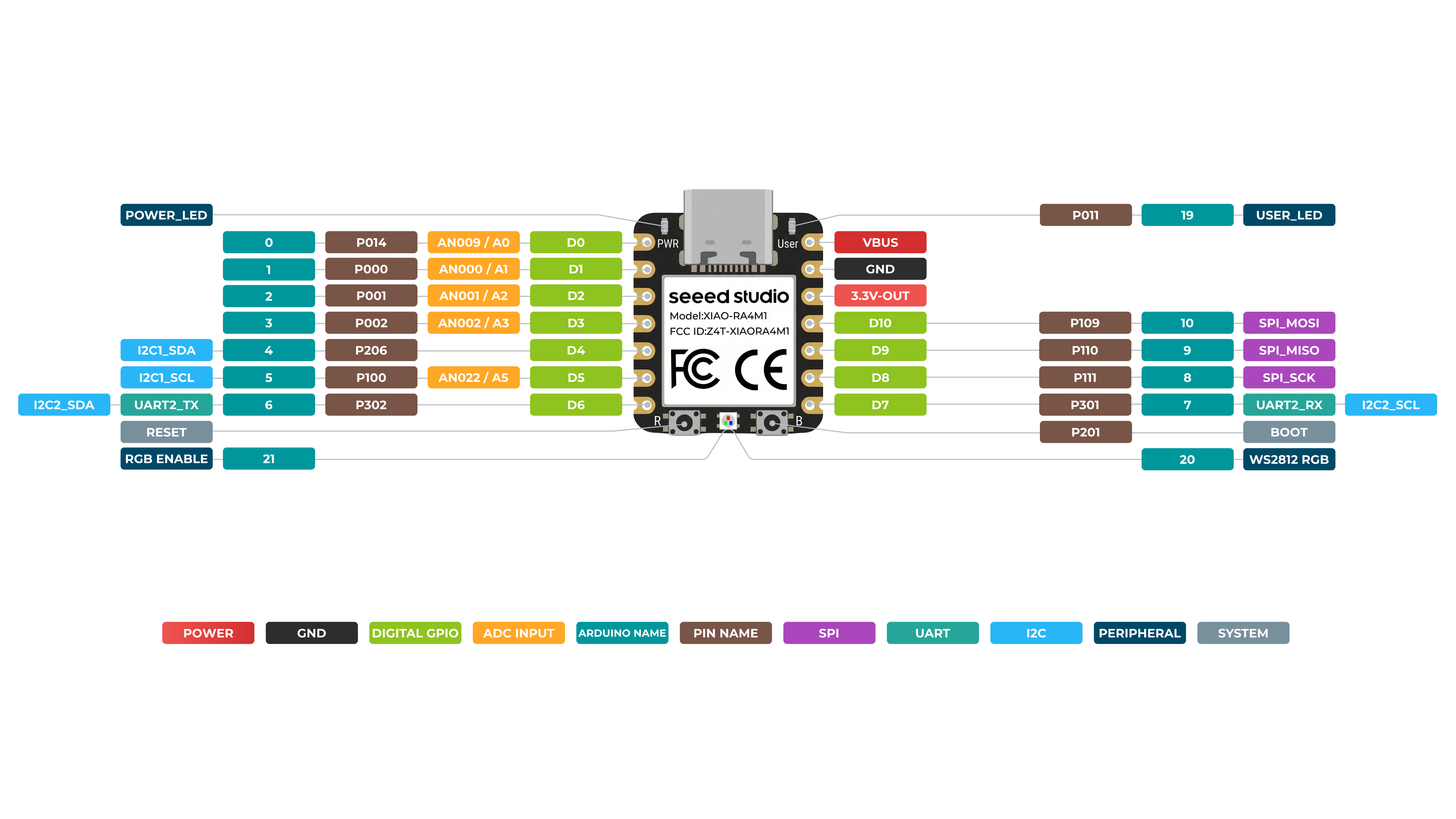
Hardware Overview
Before everything starts, it is quite essential to have some basic parameters of the product. The following table provides information about the characteristics of Seeed Studio XIAO RA4M1.
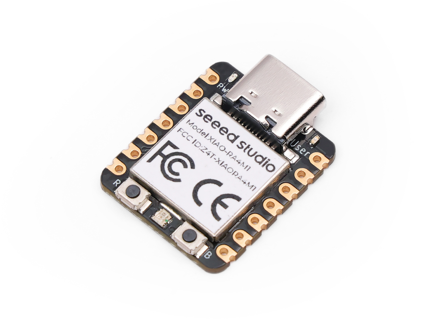
Front
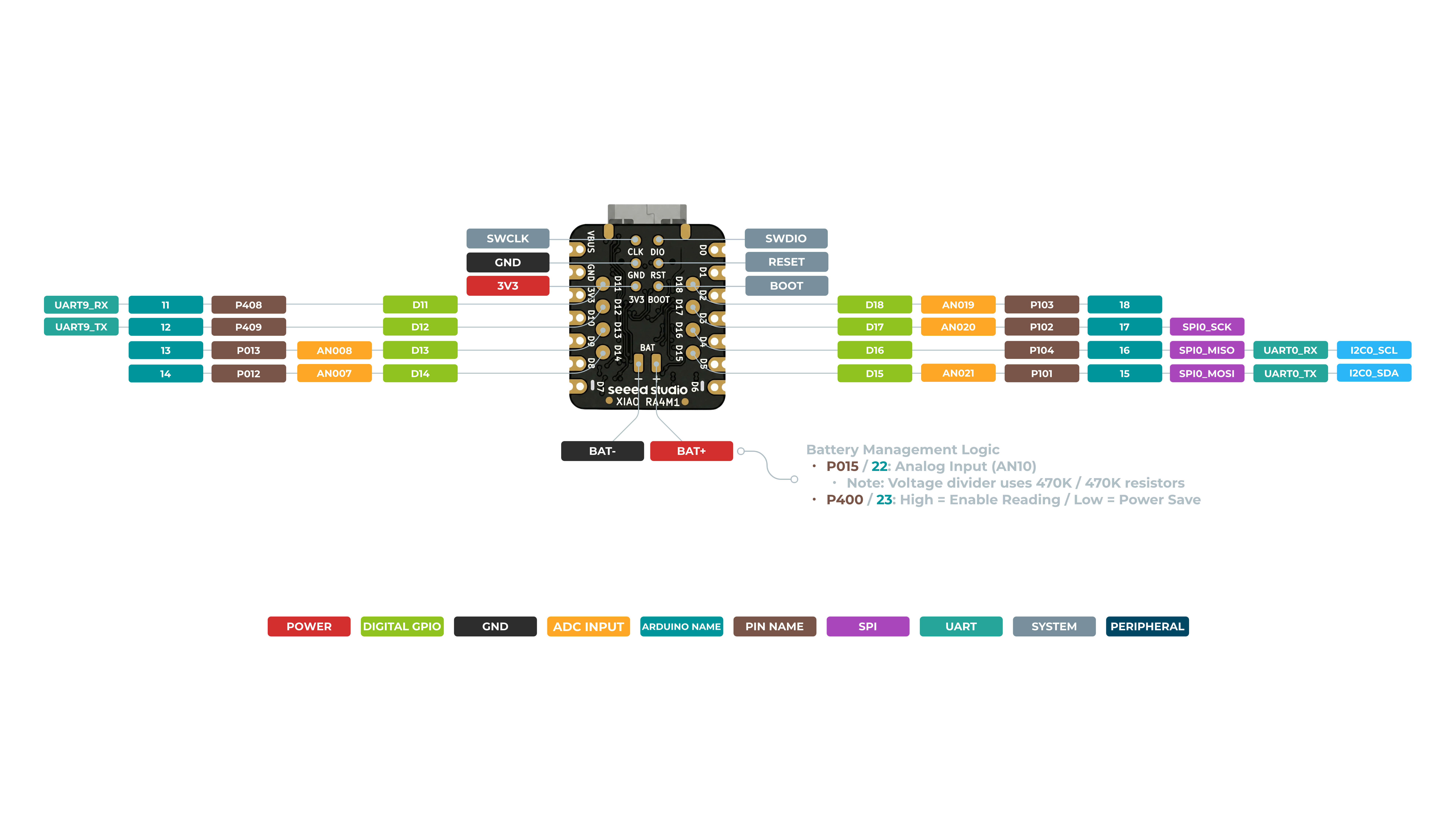
Back
Digital
The XIAO RA4M1 has up to 11 regular GPIO pins , 6 analog pins and 8 reusable IO ports behind it. In this example, we will use the XIAO RA4M1, XIAO expansion board, and a relay to demonstrate how to use different digital pins for reading and writing.
Hardware Preparation
| Seeed Studio XIAO R4M1 | Seeed Studio Expansion Base for XIAO with Grove OLED | Grove - Relay |
|---|---|---|
 |  |  |
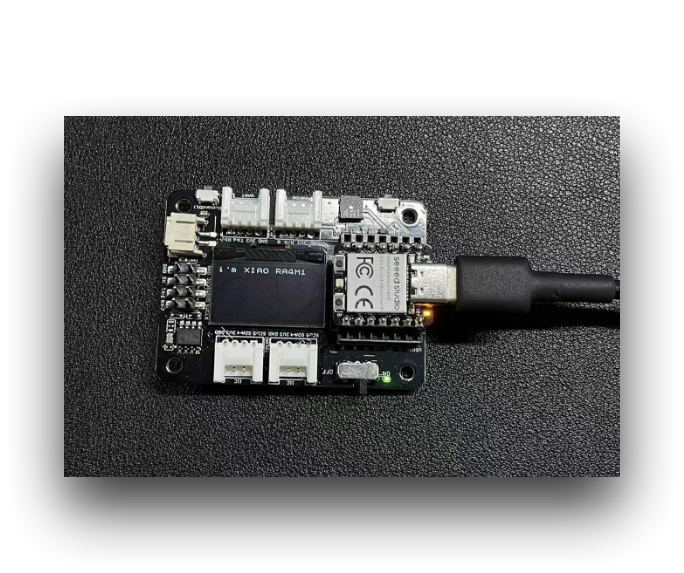
Please install XIAO RA4M1 or Sense onto the expansion board, and connect the relay to the A0/D0 interface of the expansion board via a Grove cable. Finally, connect XIAO to the computer via a USB-C cable.
Software Implementation
In this example, we will implement control of a relay's on/off state using a button connected to the XIAO expansion board. When the button is pressed, the relay turns on, and when the button is released, the relay turns off.
const int buttonPin = D1;     // the number of the pushbutton pin
int buttonState = 0;          // variable for reading the pushbutton status
const int relayPin = D0;

void setup() {
  // initialize the Relay pin as an output:
  pinMode(relayPin, OUTPUT);
  // initialize the pushbutton pin as an input:
  pinMode(buttonPin, INPUT_PULLUP);
}

void loop() {
  // read the state of the pushbutton value:
  buttonState = digitalRead(buttonPin);

  // check if the pushbutton is pressed. If it is, the buttonState is HIGH:
  if (buttonState == HIGH) {
    // turn Relay on:
    digitalWrite(relayPin, HIGH);
  } else {
    // turn Relay off:
    digitalWrite(relayPin, LOW);
  }
}
If everything goes smoothly, after uploading the program, you should see the following effect.
Digital as PWM
All GPIO pins on XIAO RA4M1 support PWM output. Therefore, you can use any pin to output PWM to adjust the brightness of lights, control servos, and other functions.
Hardware Preparation
| Seeed Studio XIAO RA4M1 | Seeed Studio Expansion Base for XIAO with Grove OLED | Grove - Variable Color LED |
|---|---|---|
| |  |
Please install XIAO RA4M1 or Sense onto the expansion board, then connect the Variable Color LED to the A0/D0 interface of the expansion board using a Grove cable. Finally, connect XIAO to your computer via USB-C cable.
Software Implementation
In this example, we will demonstrate how to use PWM output to control the brightness of a light.
int LED_pin = D0;    // LED connected to digital pin 10

void setup() {
  // declaring LED pin as output
  pinMode(LED_pin, OUTPUT);
}

void loop() {
  // fade in from min to max in increments of 5 points:
  for (int fadeValue = 0 ; fadeValue <= 255; fadeValue += 3) {
    // sets the value (range from 0 to 255):
    analogWrite(LED_pin, fadeValue);
    // wait for 30 milliseconds to see the dimming effect
    delay(30);
  }

  // fade out from max to min in increments of 5 points:
  for (int fadeValue = 255 ; fadeValue >= 0; fadeValue -= 3) {
    // sets the value (range from 0 to 255):
    analogWrite(LED_pin, fadeValue);
    // wait for 30 milliseconds to see the dimming effect
    delay(30);
  }
}
If the program runs successfully, you will see the following running effect.
Analog
XIAO RA4M1 Development Board Having up to 14 bit ADC for high-resolution reading of analog sensor values , it can help us to read more accurate val The analog-to-digital converter(ADC) on an XIAO RA4M1 Development board . By Default , the resolution is set 10-bit , which can be to both 12-bit and 14-bit resolution for improved accuracy on analog readings
Detail Datas by ADC accuracy
- 10-bit : 0~1024
- 12-bit : 0~4096
- 14-bit : 0~16383
Next , We will choose two sensors to reflect the characteristics of ADC .
Hadware Preparation
| Seeed Studio XIAO RA4M1 | Grove-Variable Color LED | Grove-Rotary Angle Sensor | Seeed Studio Grove Base for XIAO |
|---|---|---|---|
| |  |  |
Software Implementation
#define ADC_Bit_Fourteen 14
#define ADC_Bit_Twelve 12
#define ADC_Bit_Ten 10

const int analogInPin = A1;  // Analog input pin that the potentiometer is attached to
const int analogOutPin = 9;  // Analog output pin that the LED is attached to

int sensorValue = 0;  // value read from the pot
int outputValue = 0;  // value output to the PWM (analog out)

void setup() {

  Serial.begin(115200);
  // Ten_Bite_ADC_Config(); // 10bit
  // Twelve_Bite_ADC_Config(); // 12bit
  Fourteen_Bite_ADC_Config(); // 14bit

}

void loop() {
  sensorValue = analogRead(analogInPin);
  outputValue = map(sensorValue, 0, 4095, 0, 255);
  analogWrite(analogOutPin, outputValue);

  Serial.print("sensor = ");
  Serial.print(sensorValue);
  Serial.print("\t output = ");
  Serial.println(outputValue);
  delay(100);
}

void Ten_Bite_ADC_Config() {
  analogReadResolution(ADC_Bit_Ten);
}

void Twelve_Bite_ADC_Config() {
  analogReadResolution(ADC_Bit_Twelve);
}

void Fourteen_Bite_ADC_Config() {
  analogReadResolution(ADC_Bit_Fourteen);
}
If everything goes smoothly, after uploading the program, you should see the following effect.
Serial
When working with Arduino IDE, Serial communication is an essential part of many projects. To use Serial in Arduino IDE, you need to start by opening the Serial Monitor window. This can be done by clicking on the Serial Monitor icon in the toolbar or by pressing the Ctrl+Shift+M shortcut key.
General Usage
Some of the commonly used Serial functions include:
Serial.begin()-- which initializes the communication at a specified baud rate;Serial.print()-- which sends data to the Serial port in a readable format;Serial.write()-- which sends binary data to the Serial port;Serial.available()-- which checks if there is any data available to be read from the Serial port;Serial.read()-- which reads a single byte of data from the Serial port;Serial.flush()-- which waits for the transmission of outgoing serial data to complete.
By using these Serial functions, you can send and receive data between the Arduino board and your computer, which opens up many possibilities for creating interactive projects.
Here is an example program:
void setup() {
  // initialize serial communication at 9600 bits per second:
  Serial.begin(9600);
}

void loop() {
  // send data to the serial port
  Serial.println("Hello World!");

  // read data from the serial port
  if (Serial.available() > 0) {
    // read the incoming byte:
    char incomingByte = Serial.read();
    // print the incoming byte to the serial monitor:
    Serial.print("I received: ");
    Serial.println(incomingByte);
  }

  // wait for a second before repeating the loop
  delay(1000);
}
Usage of Serial1
According to the above XIAO RA4M1 Pin diagrams for specific parameters, we can observe that there are TX pin and RX pin. This is different from serial communication, but the usage is also very similar, except that a few parameters need to be added. So next, we will use the pins led out by the chip for serial communication.
#define BAUD 115200

void setup() {
    Serial1.begin(BAUD);
}

void loop() {
  if(Serial1.available() > 0)
  {
    char incominByte = Serial1.read();
    Serial1.print("I received : ");
    Serial1.println(incominByte);
  }
  delay(1000);
}
Usage of Software Serial
#include <SoftwareSerial.h>

SoftwareSerial mySerial(2, 3); // RX, TX

void setup() {
  // initialize serial communication
  Serial.begin(9600);
  while (!Serial);

  // initialize software serial
  mySerial.begin(9600);
}

void loop() {
  // read data from software serial
  if (mySerial.available()) {
    char data = mySerial.read();
    Serial.print("Received data: ");
    Serial.println(data);
  }

  // write data to software serial
  mySerial.print("Hello World!");

  // wait for a second before repeating the loop
  delay(1000);
}
In this program, we first include the SoftwareSerial.h library to use software serial. Then, we create a new SoftwareSerial object called mySerial using pins 2 and 3 as RX and TX, respectively.
In the setup() function, we initialize both the hardware serial (Serial.begin()) and the software serial (mySerial.begin()).
In the loop() function, we use the mySerial.available() function to check if there is any data available to be read from the software serial. If there is, we read the incoming byte using the mySerial.read() function and store it in a variable called data. We then use the Serial.print() and Serial.println() functions to print "Received data: " followed by the value of data to the hardware serial.
We also use the mySerial.print() function to write "Hello World!" to the software serial. This will send the data from the XIAO to the device connected to the software serial port.
Finally, we add a delay() function to wait for one second before repeating the loop.
IIC
XIAO RA4M1 has an I2C interface that can be used for data transmission and parsing of many sensors, as well as for using some OLED screens.
Harware Preparation
| Seeed Studio XIAO RA4M1 | Seeed Studio Expansion Base for XIAO with Grove OLED |
|---|---|
| |
The OLED display on the XIAO expansion board uses the I2C protocol and is connected to the XIAO's I2C interface through the I2C circuit on the board. Therefore, we can directly plug the XIAO into the expansion board and program it to display content on the screen.
Software Implementation
This example introduces how to use the OLED display on the Seeed Studio Expansion Base for XIAO RA4M1.
Step 1. Install the Seeed Studio XIAO RA4M1 on the Expansion board then conect the Type-C cable
Step 2. Install the u8g2 library
Step 3. Copy the code and stick on the Ardiono IDE then upload it
#include <Arduino.h>
#include <U8x8lib.h>
#include <Wire.h>

U8X8_SSD1306_128X64_NONAME_HW_I2C u8x8(/* clock=*/ SCL, /* data=*/ SDA, /* reset=*/ U8X8_PIN_NONE);   // OLEDs without Reset of the Display

void setup(void) {
  u8x8.begin();
  u8x8.setFlipMode(1);   // set number from 1 to 3, the screen word will rotary 180
}

void loop(void) {
  u8x8.setFont(u8x8_font_chroma48medium8_r);
  u8x8.setCursor(0, 0);
  u8x8.print("i'm XIAO RA4M1");
}
In the first few lines of the code, we include the required libraries such as Arduino.h, U8x8lib.h, and Wire.h. The U8x8lib.h library provides functions to control the OLED display, and the Wire.h library provides functions for I2C communication.
In the setup() function, we initialize the OLED display using the u8x8.begin() function. We also set the flip mode of the display using the u8x8.setFlipMode() function to rotate the screen 180 degrees.
In the loop() function, we set the font using the u8x8.setFont() function and specify the position of the cursor on the display using the u8x8.setCursor() function. Finally, we use the u8x8.print() function to display the string "Hello World!" on the OLED display.
If you upload a program to XIAO RA4M1, you will see content displayed on the OLED display screen on the expansion board.
SPI
The RA4M1 chip integrates multiple peripherals, including an SPI interface that can be used to connect external SPI devices such as flash memory, displays, sensors, and more. The XIAO RA4M1 also supports high-speed SPI transfer mode, which can achieve a maximum SPI transfer rate of 80 MHz, meeting the data transfer needs of most SPI devices.
Hadware Preparation
| Seeed Studio XIAO RA4M1 | Grove - OLED Display 1.12 (SH1107) V3.0 - SPI/IIC |
|---|---|
| _V3.0/img/10402050_Main-02.png) |
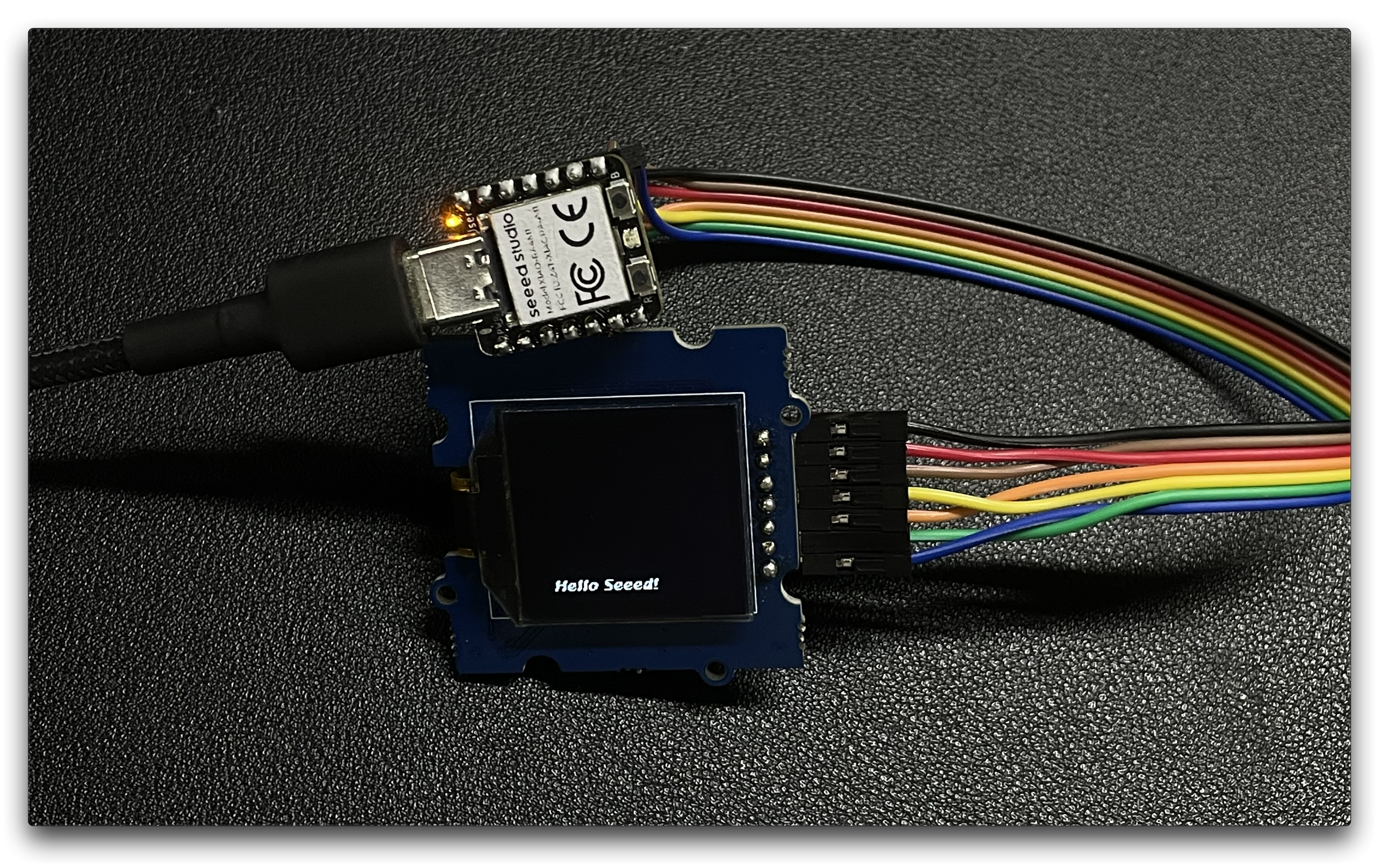
After preparing the hardware as mentioned above, use jumper wires to connect the SPI interface of the XIAO and OLED. Please refer to the following diagram for the wiring method.
Software Implementation
Next, we will take the following program as an example to introduce how to use the SPI interface to control the OLED screen display.
Install the u8g2 library.
#include <Arduino.h>
#include <U8g2lib.h>
#include <SPI.h>
#include <Wire.h>

U8G2_SH1107_128X128_1_4W_HW_SPI u8g2(U8G2_R3, /* cs=*/ D7, /* dc=*/ D4, /* reset=*/ D5);

void setup(void) {
  u8g2.begin();
}

void loop(void) {
  u8g2.firstPage();

  do {
    u8g2.setFont(u8g2_font_luBIS08_tf);
    u8g2.drawStr(0,24,"Hello Seeed!");
  } while ( u8g2.nextPage() );
}
In the setup() function, the U8G2_SH1107_128X128_1_4W_HW_SPI class is instantiated with the appropriate constructor arguments that specify the pins used for chip select (cs), data/command (dc), and reset. Then, the u8g2.begin() function is called to initialize the display.
In the loop() function, the display is updated with new content using the u8g2.firstPage(), u8g2.setFont(), and u8g2.drawStr() functions. The u8g2.firstPage() function sets up the display buffer for writing, while u8g2.nextPage() displays the updated content. The do-while loop ensures that the content is displayed continuously until the program is stopped.
Overall, this code demonstrates how to use the U8g2 library to control an OLED display and display text on it.
CAN(XIAO CAN Bus Expansion Board)
Hadware Preparation
| Seeed Studio XIAO RA4M1 | XIAO CAN Bus Expansion Board |
|---|---|
|  |
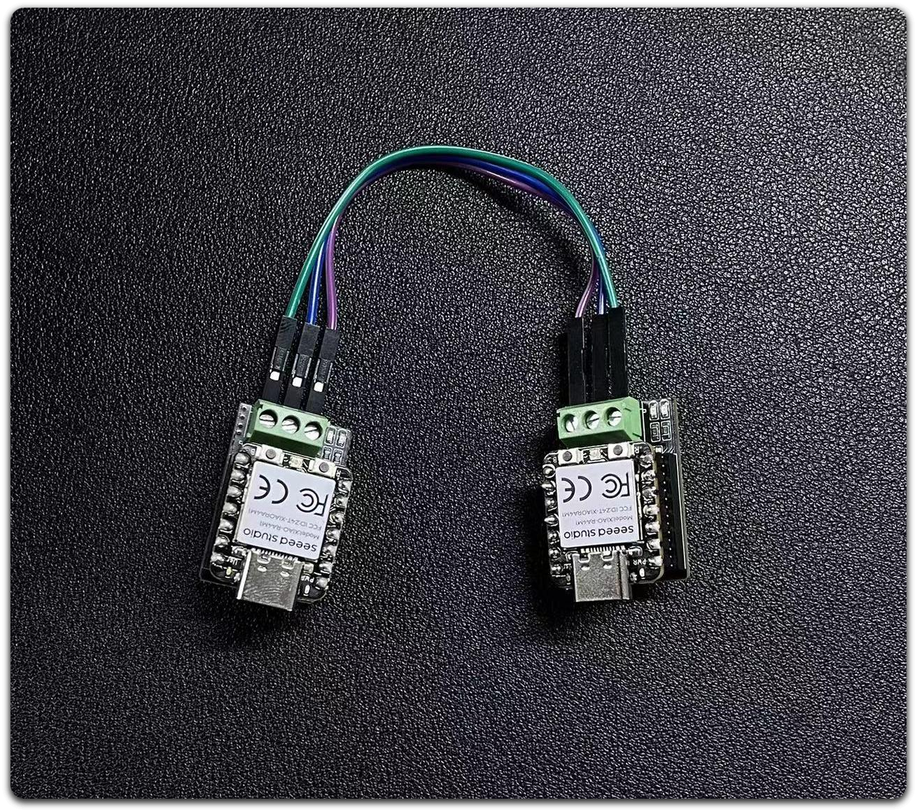
Step 1 . Prepare two CAN Bus Breakout Board and XIAO RA4M1
Step 2 . Insert these two XIAO RA4M1 separately in CAN Bus Breakout Board
Step 3 . Prepare the DuPont line connection
Software Preparation
We provide an Arduino library for the MCP2515 board.
The library includes several examples, including:
- OBDII-PIDs - retrieve data from the OBD-II interface
- send - send a frame to the CAN bus
- recv - receive a frame from the CAN bus
- set_mask_filter_recv - receive a frame from the CAN bus with mask and filter settings
Software Implementation
It is not allowed to simultaneously power on and download programs for two XIAO RA4M1s, as this will result in errors when downloading the serial port. After downloading one, unplug it, then power on the other XIAO RA4M1 to download the program, and finally power on at the same time to check the serial port message
CAN Write Code
/*  send a frame from can bus

    CAN Baudrate,

    #define CAN_5KBPS           1
    #define CAN_10KBPS          2
    #define CAN_20KBPS          3
    #define CAN_25KBPS          4
    #define CAN_31K25BPS        5
    #define CAN_33KBPS          6
    #define CAN_40KBPS          7
    #define CAN_50KBPS          8
    #define CAN_80KBPS          9
    #define CAN_83K3BPS         10
    #define CAN_95KBPS          11
    #define CAN_100KBPS         12
    #define CAN_125KBPS         13
    #define CAN_200KBPS         14
    #define CAN_250KBPS         15
    #define CAN_500KBPS         16
    #define CAN_666KBPS         17
    #define CAN_1000KBPS        18
*/

#include <mcp_can.h>
#include <SPI.h>

/* Please modify SPI_CS_PIN to adapt to your board.

   CANBed V1        - 17
   CANBed M0        - 3
   CAN Bus Shield   - 9
   CANBed 2040      - 9
   CANBed Dual      - 9
   OBD-2G Dev Kit   - 9
   OBD-II GPS Kit   - 9
   Hud Dev Kit      - 9

   Seeed Studio CAN-Bus Breakout Board for XIAO and QT Py - D7
*/

#define SPI_CS_PIN  D7

MCP_CAN CAN(SPI_CS_PIN);                                    // Set CS pin

void setup()
{
    Serial.begin(115200);
    while(!Serial);

    // below code need for OBD-II GPS Dev Kit Atemga32U4 version
    // pinMode(A3, OUTPUT);
    // digitalWrite(A3, HIGH);

    // below code need for OBD-II GPS Dev Kit RP2040 version
    // pinMode(12, OUTPUT);
    // digitalWrite(12, HIGH);

    while (CAN_OK != CAN.begin(CAN_500KBPS))    // init can bus : baudrate = 500k
    {
        Serial.println("CAN BUS FAIL!");
        delay(100);
    }
    Serial.println("CAN BUS OK!");
}

unsigned char stmp[8] = {0, 1, 2, 3, 4, 5, 6, 7};
void loop()
{
    CAN.sendMsgBuf(0x00, 0, 8, stmp);
    delay(100);                       // send data per 100ms
}

// END FILE
CAN Read Code
/*  receive a frame from can bus

    CAN Baudrate,

    #define CAN_5KBPS           1
    #define CAN_10KBPS          2
    #define CAN_20KBPS          3
    #define CAN_25KBPS          4
    #define CAN_31K25BPS        5
    #define CAN_33KBPS          6
    #define CAN_40KBPS          7
    #define CAN_50KBPS          8
    #define CAN_80KBPS          9
    #define CAN_83K3BPS         10
    #define CAN_95KBPS          11
    #define CAN_100KBPS         12
    #define CAN_125KBPS         13
    #define CAN_200KBPS         14
    #define CAN_250KBPS         15
    #define CAN_500KBPS         16
    #define CAN_666KBPS         17
    #define CAN_1000KBPS        18

    CANBed V1: https://www.longan-labs.cc/1030008.html
    CANBed M0: https://www.longan-labs.cc/1030014.html
    CAN Bus Shield: https://www.longan-labs.cc/1030016.html
    OBD-II CAN Bus GPS Dev Kit: https://www.longan-labs.cc/1030003.html
*/

#include <SPI.h>
#include "mcp_can.h"

/* Please modify SPI_CS_PIN to adapt to your board.

   CANBed V1        - 17
   CANBed M0        - 3
   CAN Bus Shield   - 9
   CANBed 2040      - 9
   CANBed Dual      - 9
   OBD-2G Dev Kit   - 9
   OBD-II GPS Kit   - 9
   Hud Dev Kit      - 9

   Seeed Studio CAN-Bus Breakout Board for XIAO and QT Py - D7
*/


#define SPI_CS_PIN  D7

MCP_CAN CAN(SPI_CS_PIN);                                    // Set CS pin


void setup()
{
    Serial.begin(115200);
    while(!Serial);

    // below code need for OBD-II GPS Dev Kit Atemga32U4 version
    // pinMode(A3, OUTPUT);
    // digitalWrite(A3, HIGH);

    // below code need for OBD-II GPS Dev Kit RP2040 version
    // pinMode(12, OUTPUT);
    // digitalWrite(12, HIGH);

    while (CAN_OK != CAN.begin(CAN_500KBPS))    // init can bus : baudrate = 500k
    {
        Serial.println("CAN BUS FAIL!");
        delay(100);
    }
    Serial.println("CAN BUS OK!");
}


void loop()
{
    unsigned char len = 0;
    unsigned char buf[8];

    if(CAN_MSGAVAIL == CAN.checkReceive())            // check if data coming
    {
        CAN.readMsgBuf(&len, buf);    // read data,  len: data length, buf: data buf

        unsigned long canId = CAN.getCanId();

        Serial.println("-----------------------------");
        Serial.print("Get data from ID: ");
        Serial.println(canId, HEX);

        for(int i = 0; i<len; i++)    // print the data
        {
            Serial.print(buf[i], HEX);
            Serial.print("\t");
        }
        Serial.println();
    }
}

// END FILE
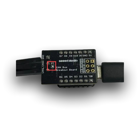
In this example , you need to solder one of the CAN Bus Breakout Board terminal pins P1 , Only then can any speed be used , otherwise you only can use below 125 CAN baudrate
CAN(Other transceiver)
We would like to thank Arduino for providing the tutorials and code.
Hardware Preparation
The CAN protocol requires that the sending end must receive the message it sends. Simply connecting TX and RX is not enough to complete communication; a transceiver must be connected for communication. Here, we use the official Arduino SN65HVD230 splitter module.
| 3.3 V | GND | D9(CANRX0) | D10 (CANTX0) |
|---|---|---|---|
| VCC | GND | CANRX | CANTX |
Software Preparation
CAN Write Code
/*
  CANWrite

  Write and send CAN Bus messages

  See the full documentation here:
  https://docs.arduino.cc/tutorials/uno-r4-wifi/can
*/

/**************************************************************************************
 * INCLUDE
 **************************************************************************************/

#include <Arduino_CAN.h>

/**************************************************************************************
 * CONSTANTS
 **************************************************************************************/

static uint32_t const CAN_ID = 0x20;

/**************************************************************************************
 * SETUP/LOOP
 **************************************************************************************/

void setup()
{
  Serial.begin(115200);
  while (!Serial) { }

  if (!CAN.begin(CanBitRate::BR_250k))
  {
    Serial.println("CAN.begin(...) failed.");
    for (;;) {}
  }
}

static uint32_t msg_cnt = 0;

void loop()
{
  /* Assemble a CAN message with the format of
   * 0xCA 0xFE 0x00 0x00 [4 byte message counter]
   */
  uint8_t const msg_data[] = {0xCA,0xFE,0,0,0,0,0,0};
  memcpy((void *)(msg_data + 4), &msg_cnt, sizeof(msg_cnt));
  CanMsg const msg(CanStandardId(CAN_ID), sizeof(msg_data), msg_data);

  /* Transmit the CAN message, capture and display an
   * error core in case of failure.
   */
  if (int const rc = CAN.write(msg); rc < 0)
  {
    Serial.print  ("CAN.write(...) failed with error code ");
    Serial.println(rc);
    for (;;) { }
  }

  /* Increase the message counter. */
  msg_cnt++;

  /* Only send one message per second. */
  delay(1000);
}
CAN Read Code
/*
  CANRead

  Receive and read CAN Bus messages

  See the full documentation here:
  https://docs.arduino.cc/tutorials/uno-r4-wifi/can
*/

/**************************************************************************************
 * INCLUDE
 **************************************************************************************/

#include <Arduino_CAN.h>

/**************************************************************************************
 * SETUP/LOOP
 **************************************************************************************/

void setup()
{
  Serial.begin(115200);
  while (!Serial) { }

  if (!CAN.begin(CanBitRate::BR_250k))
  {
    Serial.println("CAN.begin(...) failed.");
    for (;;) {}
  }
}

void loop()
{
  if (CAN.available())
  {
    CanMsg const msg = CAN.read();
    Serial.println(msg);
  }
}
When do I need to connect the terminal resistor?
-
- Long distance communication: If the CAN bus is long (e.g. more than 1 meter), terminal resistors must be connected at both ends of the bus to avoid communication problems caused by signal reflection.
-
- Multi node communication: If multiple nodes are connected to the same CAN bus, terminal resistors are also indispensable. They ensure the impedance stability of the bus, thereby preventing signal distortion.
When can the terminal resistor be disconnected?
-
- Short distance communication: In some short distance applications (usually less than 1 meter), terminal resistors can be omitted because the impact of signal reflection on communication is relatively small.
-
- Single node communication: If there is only one node on the bus (such as in a debugging environment) and the distance is short, the terminal resistor can be temporarily disconnected.
| Sender Code Result | Rceciver Code Result |
|---|---|
 |  |
Tech Support & Product Discussion
Thank you for choosing our products! We are here to provide you with different support to ensure that your experience with our products is as smooth as possible. We offer several communication channels to cater to different preferences and needs.