Seeed Studio XIAO RP2350 with Arduino
The Seeed Studio XIAO RP2350 board now supports programming via Arduino, thanks to the arduino-pico core. This guide will help you set up and begin using Arduino on your RP2350 board.
Features
- Powerful MCU Board: Equipped with a Raspberry Pi RP2350 chip featuring symmetric dual Arm Cortex-M33 @ 150MHz with FPU.
- Enhanced Security Features: Built-in secure boot and encrypted bootloader ensure application security.
- Software Support: Compatible with C/C++ and MicroPython, ensuring easy project development and prototyping.
- Rich Onboard Resources: Integrates an RGB LED, 2MB Flash, 520kB SRAM, and 19 multifunction GPIOs(Analog, Digital, I²C, UART, SPI, PWM).
- Expanded 8 New IOs: Compared to previous XIAO MCUs, the addition of 8 IO pins on the back supports more complex applications.
- Efficient Power Design: Ultra-low power consumption of just 50μA in sleep mode, enabling battery power supply. Direct battery voltage measurement via internal IO enhances the battery management system (BMS).
- Compact Thumb-Sized Design: Measuring 21 x 17.8mm, adopting Seeed Studio's classic XIAO form factor, ideal for space-conscious applications.
- Production-friendly: Surface Mount Device (SMD) design with all components on the front and stamp holes on both sides, facilitating efficient mass production.
Specification
| Product | XIAO RP2040 | XIAO RP2350 |
|---|---|---|
| Processor | Raspberry Pi RP2040 Dual Cortex-M0+ @ 133MHz | Raspberry Pi RP2350 Dual Cortex-M33 @ 150MHz, FPU |
| RAM | 264kB SRAM | 520kB SRAM |
| Flash | 2MB Onboard | 2MB Flash |
| LEDs | 1x user LED 1x power LED 1x RGB LED | 1x user LED 1x power LED 1x RGB LED |
| Interface | 11 Pins (All PWM): 4x Analog 11x Digital 1x I²C 1x UART 1x SPI | 19 Pins (All PWM): 3x Analog 19x Digital 2x I²C 2x UART 2x SPI |
| Button | 1x RESET button 1x BOOT button | 1x RESET button 1x BOOT button |
| Security | - | OTP, Secure Boot, Arm TrustZone |
| Software compatibility | Support Micropython / Arduino / CircuitPython | Support Micropython / Arduino / C,C++ |
| Working Temperature | -20°C-70°C | -20°C-70°C |
| Dimensions | 21x17.8 mm | 21x17.8 mm |
Hardware Overview
| XIAO RP2350 Front Pinout |
|---|
 |
| XIAO RP2350 Back Pinout |
 |
| XIAO RP2350 Components |
 |
Need more details on pinouts? Navigate to Assets and Resources below.
Pin Map
| XIAO Pin | Function | Chip Pin | Alternate Functions | Description |
|---|---|---|---|---|
| 5V | VBUS | Power Input/Output | ||
| GND | ||||
| 3V3 | 3V3_OUT | Power Output | ||
| D0 | Analog | GPIO26 | GPIO, ADC | |
| D1 | Analog | GPIO27 | GPIO, ADC | |
| D2 | Analog | GPIO28 | GPIO, ADC | |
| D3 | SPIO_CSn | GPIO5 | GPIO, SPI | |
| D4 | SDA1 | GPIO6 | GPIO, I2C Data | |
| D5 | SCL1 | GPIO7 | GPIO, I2C Clock | |
| D6 | TX0 | GPIO0 | GPIO, UART Transmit | |
| D7 | RX0 | GPIO1 | GPIO, UART Receive | |
| D8 | SPIO_SCK | GPIO2 | GPIO, SPI Clock | |
| D9 | SPIO_MISO | GPIO4 | GPIO, SPI Data | |
| D10 | SPIO_MOSI | GPIO3 | GPIO, SPI Data | |
| D11 | RX1 | GPIO21 | GPIO, UART Receive | |
| D12 | TX1 | GPIO20 | GPIO, UART Transmit | |
| D13 | SCL0 | GPIO17 | GPIO, I2C Clock | |
| D14 | SDA0 | GPIO16 | GPIO, I2C Data | |
| D15 | SPI1_MOSI | GPIO11 | GPIO, SPI Data | |
| D16 | SPI1_MISO | GPIO12 | GPIO, SPI Data | |
| D17 | SPI1_SCK | GPIO10 | GPIO, SPI Clock | |
| D18 | SPI1_Csn | GPIO9 | Csn | |
| ADC_BAT | GPIO29 | Read the BAT voltage value | ||
| Reset | RUN | RUN | ||
| Boot | RP2040_BOOT | Enter Boot Mode | ||
| CHARGE_LED | NCHG | CHG-LED_Red | ||
| RGB LED | GPIO22 | RGB LED | ||
| USER_LED | GPIO25 | User Light_Yellow |
Prerequisites
To get started, ensure you have:
- An RP2350 board
- The Arduino IDE
- A USB cable
Setting Up the Software
1. Install the Arduino IDE
Download and install the latest Arduino IDE from the official site: Arduino Software.
2. Add RP2350 Board Support
-
Open the Arduino IDE and navigate to File > Preferences.
-
In the Additional Boards Manager URLs field, add this URL:
https://github.com/earlephilhower/arduino-pico/releases/download/global/package_rp2040_index.json
-
Click OK to save your settings.
-
Go to Tools > Board > Boards Manager.
-
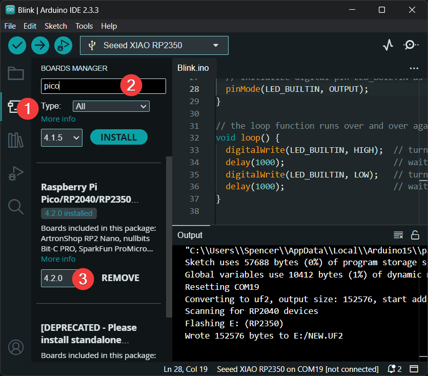
In the Boards Manager, search for pico and click Install.
-
After installation, go to Tools > Board and select the board shown below as your board.
Ensure you install version 4.2.0 or later for full support of the XIAO RP2350 board.
3. Uploading a Sketch
Before uploading a sketch, place your XIAO RP2350 into BOOT mode. Use one of the methods below:
- Method 1: Before Connecting to Computer
- Method 2: While Connected to Computer
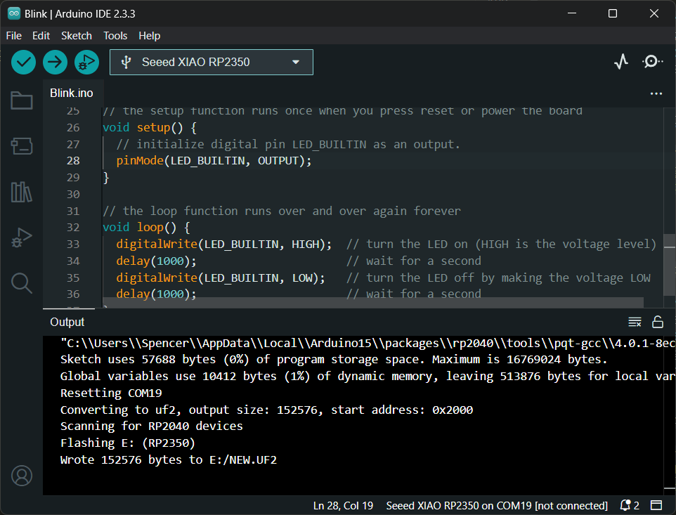
- Open the Arduino IDE and create a new sketch.
- Write your code. For example, use the
Blinkexample code. - Go to Tools > Port and select the port where your RP2350 is connected.
Assets & Resources
Hardware Design
- 📄[Datasheet] Raspberry Pi RP2350 Datasheet
- 📄[Schematic] XIAO RP2350 Schematic
- 🗃️[PCB Design Files] XIAO RP2350 KiCad Project
- 🗃️[PCB Design Libraries]
- 📄[Pinout Diagram] XIAO RP2350 Pinout Sheet
Mechanical Design
- 📄[2D Dimensions] XIAO RP2350 Dimension in DXF
- 🔗[3D Model] XIAO RP2350 3D Model
Software & Tools
- 📄[Test Firmware] XIAO RP2350 Low Power Test Firmware
Others
- 📄[Document] Getting Started with Raspberry Pi Pico-series
- A comprehensive guide to setting up and programming Raspberry Pi Pico boards, ideal for beginners looking to learn MicroPython or C/C++.
- 📄[Document] Raspberry Pi Pico-series Python SDK
- The book which documents the MicroPython setup tutorials and APIs
- 📄[Document] Raspberry Pi Pico-series C/C++SDK
- The book which documents the Pico C/C++ SDK APIs
- 📄[arduino-pico GitHub](https://github.com/earlephilhower/arduino-pico)
- 📄[Arduino-Pico Core Documentation](https://arduino-pico.readthedocs.io/en/latest/install.html)
Support & Discussion
Thank you for using Seeed products! We offer multiple channels for support and community discussion: