XIAO STM32C5 Application Examples
Overview
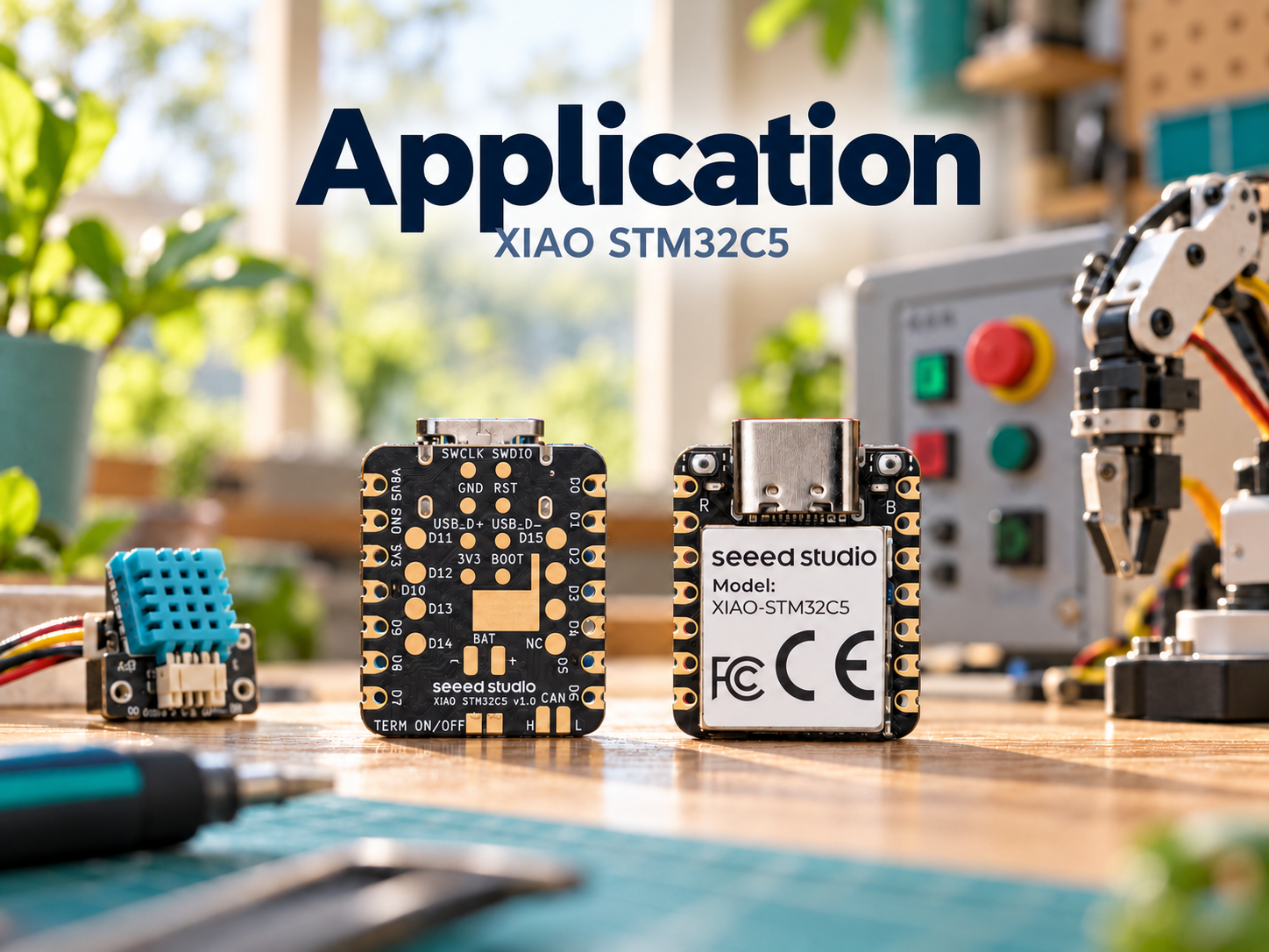
The XIAO STM32C5 is equipped with the LSM6DS3TR-C 6-axis inertial sensor, which integrates a 3-axis accelerometer and a 3-axis gyroscope. It also features an on-board CAN transceiver, directly meeting the requirements for motion sensing and CAN bus communication. With these hardware resources, you can implement various applications including attitude detection, vibration monitoring, low-power motion wake-up, interactive lighting control, CAN FD data logging and fault diagnosis.
This article uses PlatformIO. If you are not familiar with it, see Getting Started with PlatformIO for XIAO STM32C5.
IMU Usage
The XIAO STM32C5 carries an on‑board LSM6DS3TR‑C 6‑axis inertial sensor, which integrates a 3‑axis accelerometer and a 3‑axis gyroscope. It can be applied to attitude detection, motion recognition, vibration monitoring and other use‑cases.
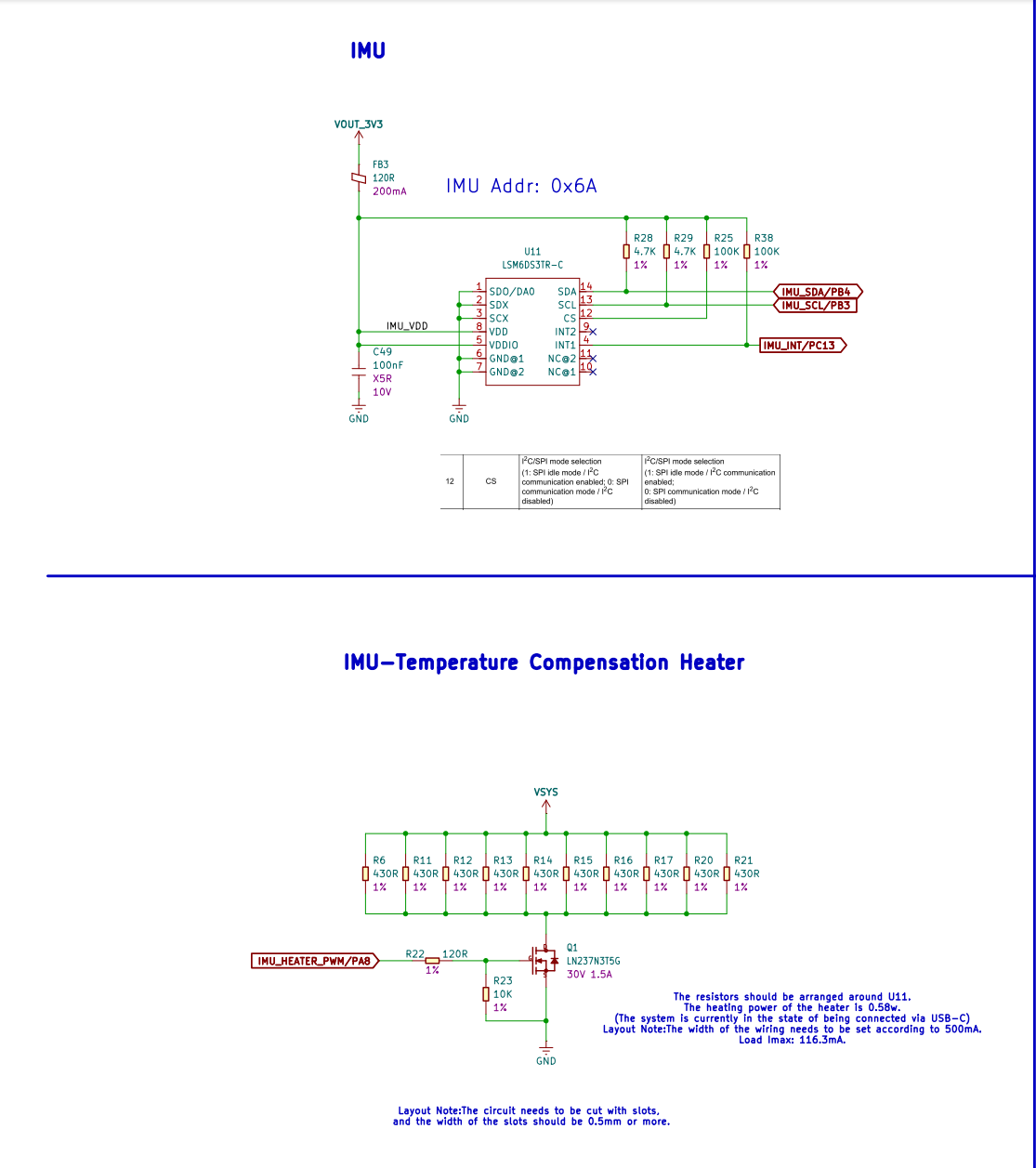
To mitigate the impact of ambient temperature variation on sensor bias and measurement stability, the board implements an active temperature‑compensation heating circuit. Heating resistors placed around the IMU provide uniform heating for the sensor, and heating power can be adjusted via PWM signals. Combined with internal temperature readings from the IMU, software control keeps the sensor operating at a relatively stable temperature. This reduces measurement drift caused by temperature drift and improves data consistency during long‑term operation and under variable‑temperature conditions.
Reading 6-axis Sensor Data
- Hardware Preparation
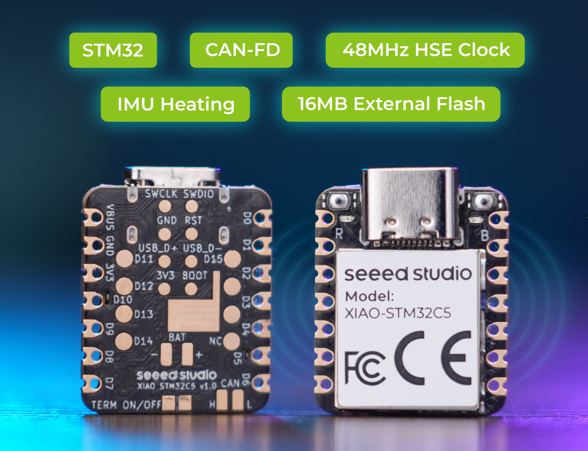
One XIAO STM32C5 board.
| Seeed Studio XIAO STM32C5 |
|---|
 |
- Software Preparation
Create a new PlatformIO project
- Modify the device tree configuration in
app.overlay
app.overlay
/*
 * No application-level devicetree overrides are required.
 *
 * The board DTS supplies imu0 as the LSM6DS3TR-C on I2C2:
 *   address 0x6a, SCL PB3, SDA PB4.
 *
 * The board DTS also describes INT1 on PC13 and the heater on PA8/TIM1_CH1,
 * but this polling-only application does not configure an IMU trigger and
 * does not enable or access PWM.  Those board-level nodes remain unchanged.
 */
- Modify
prj.confto enable fixed-rate polling sampling for the LSM6DS3TR-C 6-axis sensor, along with USB CDC ACM serial console output.
prj.conf
# LSM6DS3TR-C six-axis polling sample.
CONFIG_SENSOR=y
CONFIG_I2C=y

# Fixed sensor configuration: 104 Hz, accel +/-4g, gyro +/-500 dps.
CONFIG_LSM6DSL_ACCEL_ODR=4
CONFIG_LSM6DSL_ACCEL_FS=4
CONFIG_LSM6DSL_GYRO_ODR=4
CONFIG_LSM6DSL_GYRO_FS=500

# USB CDC ACM console for sample output.
CONFIG_SERIAL=y
CONFIG_CONSOLE=y
CONFIG_UART_CONSOLE=y
CONFIG_UF2_DFU_RESET=y
CONFIG_USB_DEVICE_STACK_NEXT=y
CONFIG_USBD_CDC_ACM_CLASS=y
CONFIG_UART_LINE_CTRL=y

# Deliberately not enabled:
# CONFIG_PWM
# CONFIG_LSM6DSL_ENABLE_TEMP
# CONFIG_LSM6DSL_TRIGGER
- Modify main.c
main.c
/*
 * Copyright (c) 2026 Seeed Technology Co., Ltd.
 * SPDX-License-Identifier: Apache-2.0
 *
 * XIAO STM32C5 onboard LSM6DS3TR-C six-axis polling sample.
 */

#include <zephyr/device.h>
#include <zephyr/devicetree.h>
#include <zephyr/drivers/sensor.h>
#include <zephyr/kernel.h>
#include <zephyr/sys/printk.h>

#define IMU_NODE DT_ALIAS(imu0)
#define SAMPLE_INTERVAL_MS 100

BUILD_ASSERT(DT_NODE_HAS_STATUS(IMU_NODE, okay),
	     "imu0 alias is not defined or not okay");

static const struct device *const imu = DEVICE_DT_GET(IMU_NODE);

static void print_value(const struct sensor_value *value)
{
	int64_t micro = sensor_value_to_micro(value);
	uint64_t magnitude = micro < 0 ? (uint64_t)(-micro) : (uint64_t)micro;

	printk("%s%lld.%06llu",
	       micro < 0 ? "-" : "",
	       (long long)(magnitude / 1000000U),
	       (unsigned long long)(magnitude % 1000000U));
}

static int read_six_axis(struct sensor_value accel[3],
			 struct sensor_value gyro[3])
{
	int ret = sensor_sample_fetch(imu);

	if (ret < 0) {
		return ret;
	}

	ret = sensor_channel_get(imu, SENSOR_CHAN_ACCEL_XYZ, accel);
	if (ret < 0) {
		return ret;
	}

	return sensor_channel_get(imu, SENSOR_CHAN_GYRO_XYZ, gyro);
}

int main(void)
{
	struct sensor_value accel[3];
	struct sensor_value gyro[3];
	int ret;

	if (!device_is_ready(imu)) {
		printk("IMU device is not ready\n");
		return 0;
	}

	printk("LSM6DS3TR-C polling: accel +/-4g, gyro +/-500 dps, 104 Hz\n");
	printk("INT1 and heater PWM are not used by this application.\n");

	while (true) {
		ret = read_six_axis(accel, gyro);
		if (ret < 0) {
			printk("IMU read failed: %d\n", ret);
			k_msleep(SAMPLE_INTERVAL_MS);
			continue;
		}

		printk("accel(m/s^2) x=");
		print_value(&accel[0]);
		printk(" y=");
		print_value(&accel[1]);
		printk(" z=");
		print_value(&accel[2]);
		printk("  gyro(rad/s) x=");
		print_value(&gyro[0]);
		printk(" y=");
		print_value(&gyro[1]);
		printk(" z=");
		print_value(&gyro[2]);
		printk("\n");

		k_msleep(SAMPLE_INTERVAL_MS);
	}

	return 0;
}
- Result
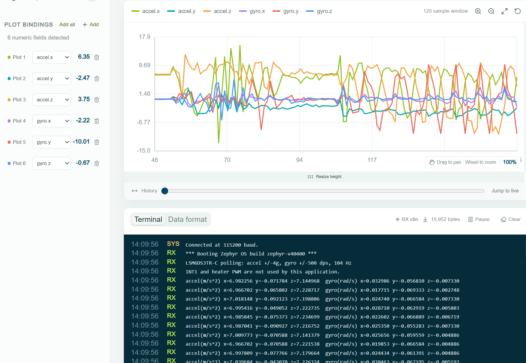
Use any serial monitor to observe the output 3-axis accelerometer and gyroscope readings.
- If PWM temperature compensation is enabled, the XIAO STM32C5 will be heated to around 40°C. Therefore, heat generation is normal.
- Code examples for PWM temperature compensation and IMU INT1 interrupt are shown below.
IMU Motion Wakeup
The onboard LSM6DS3TR-C can detect motion while the XIAO STM32C5 is in a low-power state. When motion exceeds the configured wake-up threshold, the IMU asserts INT1 to wake the board.
- Hardware Preparation
| Seeed Studio XIAO STM32C5 |
|---|
|
Before you start, prepare one XIAO STM32C5 board.
Software Preparation
- Add the STOP1 power-state configuration to app.overlay. The board DTS already defines the IMU and its INT1 pin.
app.overlay
/*
 * No IMU-specific devicetree overrides are required.
 *
 * The board DTS supplies imu0 as the LSM6DS3TR-C on I2C2:
 *   address 0x6a, SCL PB3, SDA PB4.
 *
 * The board DTS also describes INT1 on PC13 and the heater on PA8/TIM1_CH1.
 */

 / {
	power-states {
		stop1: stop1 {
			compatible = "zephyr,power-state";
			power-state-name = "suspend-to-idle";
			substate-id = <1>;
			min-residency-us = <1000>;
			exit-latency-us = <100>;
		};
	};
};

&cpu0 {
	cpu-power-states = <&stop1>;
};
- Modify the
prj.confconfiguration file.
prj.conf
CONFIG_I2C=y
CONFIG_GPIO=y
CONFIG_PM=y

CONFIG_SERIAL=y
CONFIG_CONSOLE=y
CONFIG_UART_CONSOLE=y
CONFIG_PRINTK=y
CONFIG_UF2_DFU_RESET=y
CONFIG_USB_DEVICE_STACK_NEXT=y
CONFIG_USBD_CDC_ACM_CLASS=y
CONFIG_UART_LINE_CTRL=y

# The IMU heater/temperature compensation is intentionally unused.
CONFIG_PWM=n
- Implement motion wake-up in main.c. The IMU compares motion against the configured wake-up threshold and asserts INT1 when triggered. The XIAO then wakes, logs the event and an IMU sample, and returns to sleep.
main.c
/* XIAO STM32C5 + LSM6DS3TR-C motion wake-up demo. */

#include <zephyr/device.h>
#include <zephyr/devicetree.h>
#include <zephyr/drivers/gpio.h>
#include <zephyr/drivers/i2c.h>
#include <zephyr/kernel.h>
#include <zephyr/pm/pm.h>
#include <zephyr/sys/printk.h>

#include <stm32_ll_cortex.h>
#include <stm32_ll_pwr.h>

#define IMU_NODE DT_ALIAS(imu0)

#define CTRL1_XL   0x10
#define CTRL2_G    0x11
#define CTRL3_C    0x12
#define CTRL6_C    0x15
#define WAKE_SRC   0x1b
#define OUTX_L_G   0x22
#define TAP_CFG    0x58
#define WAKE_THS   0x5b
#define WAKE_DUR   0x5c
#define MD1_CFG    0x5e

static const struct i2c_dt_spec imu = I2C_DT_SPEC_GET(IMU_NODE);
static const struct gpio_dt_spec imu_int =
	GPIO_DT_SPEC_GET(IMU_NODE, irq_gpios);
static const struct gpio_dt_spec led =
	GPIO_DT_SPEC_GET(DT_ALIAS(led0), gpios);

static struct gpio_callback imu_cb;
K_SEM_DEFINE(wake_sem, 0, 1);

extern int stm32_clock_control_init(const struct device *dev);

/* Zephyr 4.4 has no STM32C5 PM backend yet, so provide the STOP1 hooks here. */
void pm_state_set(enum pm_state state, uint8_t substate_id)
{
	if (state == PM_STATE_SUSPEND_TO_IDLE && substate_id == 1) {
		LL_PWR_SetPowerMode(LL_PWR_STOP1_MODE);
		SCB_EnableDeepSleep();
		k_cpu_idle();
	}
}

void pm_state_exit_post_ops(enum pm_state state, uint8_t substate_id)
{
	if (state == PM_STATE_SUSPEND_TO_IDLE && substate_id == 1) {
		SCB_DisableDeepSleep();
		(void)stm32_clock_control_init(NULL);
	}
	irq_unlock(0);
}

static void imu_isr(const struct device *port, struct gpio_callback *cb,
		    gpio_port_pins_t pins)
{
	ARG_UNUSED(port);
	ARG_UNUSED(cb);
	ARG_UNUSED(pins);
	k_sem_give(&wake_sem);
}

static int imu_wakeup_init(void)
{
	int ret;

	if (!i2c_is_ready_dt(&imu) || !gpio_is_ready_dt(&imu_int) ||
	    !gpio_is_ready_dt(&led)) {
		return -ENODEV;
	}

	ret = gpio_pin_configure_dt(&led, GPIO_OUTPUT_INACTIVE);
	ret |= gpio_pin_configure_dt(&imu_int, GPIO_INPUT);
	if (ret < 0) {
		return ret;
	}

	gpio_init_callback(&imu_cb, imu_isr, BIT(imu_int.pin));
	ret = gpio_add_callback(imu_int.port, &imu_cb);
	if (ret < 0) {
		return ret;
	}

	return 0;
}

static int enter_imu_low_power(void)
{
	int ret;

	/* Sleep sensing: accel 12.5 Hz low-power +/-2 g, gyro off. */
	ret = i2c_reg_write_byte_dt(&imu, MD1_CFG, 0x00);
	ret |= i2c_reg_write_byte_dt(&imu, CTRL3_C, 0x44);
	ret |= i2c_reg_write_byte_dt(&imu, CTRL2_G, 0x00);
	ret |= i2c_reg_write_byte_dt(&imu, CTRL6_C, 0x10);
	ret |= i2c_reg_write_byte_dt(&imu, CTRL1_XL, 0x10);
	ret |= i2c_reg_write_byte_dt(&imu, WAKE_THS, 0x08);
	ret |= i2c_reg_write_byte_dt(&imu, WAKE_DUR, 0x00);
	ret |= i2c_reg_write_byte_dt(&imu, TAP_CFG, 0x80);
	return ret;
}

static int arm_imu_wakeup(void)
{
	uint8_t source;
	int ret;

	/* Discard the mode-change transient only after the 500 ms settling time. */
	k_sem_reset(&wake_sem);
	ret = i2c_reg_read_byte_dt(&imu, WAKE_SRC, &source);
	ret |= i2c_reg_write_byte_dt(&imu, MD1_CFG, BIT(5));
	ret |= gpio_pin_interrupt_configure_dt(&imu_int,
					       GPIO_INT_EDGE_TO_ACTIVE);
	return ret;
}

static int16_t sample16(const uint8_t *data)
{
	return (int16_t)((uint16_t)data[0] | ((uint16_t)data[1] << 8));
}

static void print_imu_sample(void)
{
	uint8_t data[12];
	int16_t gx, gy, gz, ax, ay, az;

	/* Awake sensing: accel and gyro at 104 Hz. */
	(void)i2c_reg_write_byte_dt(&imu, MD1_CFG, 0x00);
	(void)i2c_reg_write_byte_dt(&imu, CTRL6_C, 0x00);
	(void)i2c_reg_write_byte_dt(&imu, CTRL1_XL, 0x40);
	(void)i2c_reg_write_byte_dt(&imu, CTRL2_G, 0x40);
	k_msleep(30);

	if (i2c_burst_read_dt(&imu, OUTX_L_G, data, sizeof(data)) < 0) {
		printk("IMU sample read failed\n");
		return;
	}

	gx = sample16(&data[0]);
	gy = sample16(&data[2]);
	gz = sample16(&data[4]);
	ax = sample16(&data[6]);
	ay = sample16(&data[8]);
	az = sample16(&data[10]);

	/* +/-2 g: 0.061 mg/LSB; +/-250 dps: 8.75 mdps/LSB. */
	printk("accel[mg]=%d,%d,%d gyro[mdps]=%d,%d,%d\n",
	       ax * 61 / 1000, ay * 61 / 1000, az * 61 / 1000,
	       gx * 875 / 100, gy * 875 / 100, gz * 875 / 100);
}

int main(void)
{
	uint32_t event_count = 0;
	uint8_t source;

	if (imu_wakeup_init() < 0) {
		printk("IMU wake-up init failed\n");
		return 0;
	}

	gpio_pin_set_dt(&led, 1);
	if (enter_imu_low_power() < 0) {
		printk("Failed to configure IMU low-power mode\n");
		return 0;
	}
	k_msleep(500);
	gpio_pin_set_dt(&led, 0);

	while (true) {
		if (arm_imu_wakeup() < 0) {
			printk("Failed to arm IMU wake-up\n");
			return 0;
		}

		printk("Sleeping in STOP1. Move or tap the board to wake it.\n");

		/* With no runnable work, Zephyr selects STOP1 from app.overlay. */
		k_sem_take(&wake_sem, K_FOREVER);

		(void)gpio_pin_interrupt_configure_dt(&imu_int,
						      GPIO_INT_DISABLE);
		(void)i2c_reg_write_byte_dt(&imu, MD1_CFG, 0x00);
		(void)i2c_reg_read_byte_dt(&imu, WAKE_SRC, &source);
		gpio_pin_set_dt(&led, 1);
		printk("Knock event #%u, WAKE_UP_SRC=0x%02x\n",
		       ++event_count, source);
		print_imu_sample();

		/* Let low-power acceleration settle while the LED remains on. */
		if (enter_imu_low_power() < 0) {
			printk("Failed to configure IMU low-power mode\n");
			return 0;
		}
		k_msleep(500);
		gpio_pin_set_dt(&led, 0);
	}

	return 0;
}
- Result
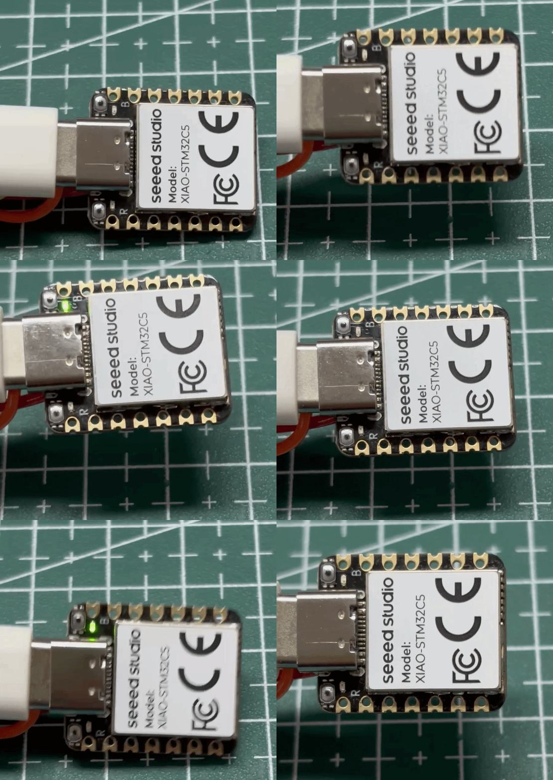
- When motion exceeds the configured threshold, INT1 wakes the board. The LED lights briefly before the board returns to sleep.
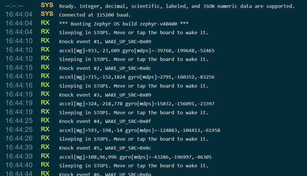
- Each wake-up prints an event number, the WAKE_UP_SRC value, and an IMU sample to the serial port.
IMU Electronic Ocean
The Electronic Ocean demo uses the IMU to sense the gravity direction and motion state of the device. Two cascaded 6×10 RGB matrices are treated as one unified 6×20 display area. The program calculates the water surface orientation from accelerometer data, and controls wave amplitude using gyroscope readings and motion intensity. It also dynamically adjusts the water level, maintaining roughly half fill of the "seawater" as the device rotates or tilts. This simulates the fluid flowing, sloshing and surging under gravity.
-
Usage:
- After power-on, the RGB LEDs stay off by default, waiting for wakeup.
- Wake the Electronic Ocean by shaking the device noticeably or holding the button for 2 seconds.
- Tilt the device slowly; the water surface will shift smoothly following gravity.
- Move the device moderately to intensify wave undulation and surging effects.
- Short-press the button to switch display modes: neon, deep-sea blue, sky cyan, purple breathing, scrolling text and more.
- Hold the button for 2 seconds or shake the device firmly during operation to manually enter sleep mode.
- If the device attitude remains nearly unchanged for 90 consecutive seconds, the RGB LEDs will turn off automatically and wait to be woken by IMU events or button input.
-
Hardware Preparation
| Seeed Studio XIAO STM32C5 | 6x10 RGB WS2812 Matrix for Seeed Studio XIAO × 2 | Grove Button |
|---|---|---|
|  |  |
- Software Preparation
- Modify the
app.overlayfile to enable the configured pins. Here, D1 is selected for button control, and D0 serves as the signal pin for driving the RGB WS2812 Matrix.
app.overlay
#include <zephyr/dt-bindings/gpio/gpio.h>

/ {
	aliases {
		rgb-data = &rgb_matrix_data;
		imu-wake = &imu_wake;
		mode-button = &mode_button;
	};

	mode_buttons {
		compatible = "gpio-keys";
		mode_button: mode-button {
			gpios = <&gpioa 1 (GPIO_PULL_DOWN | GPIO_ACTIVE_HIGH)>;
			label = "Grove Button on D1";
		};
	};

	imu_wake_pins {
		compatible = "gpio-keys";
		imu_wake: imu-wake {
			gpios = <&gpioc 13 GPIO_ACTIVE_HIGH>;
			label = "LSM6DS3TR-C INT1";
		};
	};

	/* D0/PA0 drives two cascaded 6 x 10 panels (first DOUT -> second DIN). */
	rgb_matrix_pins {
		compatible = "gpio-leds";

		rgb_matrix_data: rgb-matrix-data {
			gpios = <&gpioa 0 GPIO_ACTIVE_HIGH>;
		};
	};
};

/* The on-board LSM6DS3TR-C is polled at 50 Hz to animate the ocean. */
&i2c2 {
	status = "okay";
};

&lsm6ds3tr_c {
	status = "okay";
};
- Modify the
prj.confconfiguration file.
prj.conf
CONFIG_GPIO=y
CONFIG_I2C=y
CONFIG_SENSOR=y
CONFIG_LSM6DSL=y
CONFIG_PRINTK=y
CONFIG_MAIN_STACK_SIZE=4096
-
Implement the logic in
main.c. Since the reference code is quite long, navigate to the code file and copy its contents intomain.c.- 📄[c-file] electronic-ocean-main.c
-
result
- When the device is stationary or enters sleep mode, the RGB lights turn off, and the IMU remains in low-power motion detection.
- Shake the device; the IMU interrupt triggers wakeup, and the RGB ocean effect lights up again.
- Tilt the device slowly, and the sea level will incline smoothly following gravity, just like the water surface inside a container.
- When changing the device orientation, the seawater flows continuously across the entire RGB matrix.
- As the movement or shaking intensity increases, the wave undulation and surging effects become stronger accordingly.
- If the attitude stays unchanged for a long time, or after a noticeable shake, the lights will turn off again and return to the wakeup-waiting state.
- 3D‑printable enclosure files are available below
- USB‑C charging is supported after installing a battery. Please refer to Battery Usage.
- If you intend to fit a battery inside the enclosure, the recommended lithium‑ion battery is KXW 402030 (3.7 V, 200 mAh, 0.74 Wh).
CAN Logger
The XIAO STM32C5 features two‑channel CAN FD peripherals on‑board. It is equipped with the TCAN3403-Q1 transceiver, and a 120‑ohm termination resistor is pre‑configured. You can directly use the CAN_H and CAN_L solder pad interfaces on the back side for CAN‑BUS‑related applications.
For more information about CAN and CAN‑FD usage on the XIAO STM32C5, please refer to XIAO STM32C5 CANFD Usage
In CAN BUS applications, analysis of CAN payload data, verification of successful transmission and reception, packet loss rate and other related factors are critical for practical deployment. However, the CAN BUS protocol is complex, making troubleshooting challenging for developers. Certain tools are therefore required to preliminarily identify faulty nodes on the CAN BUS for further diagnosis.
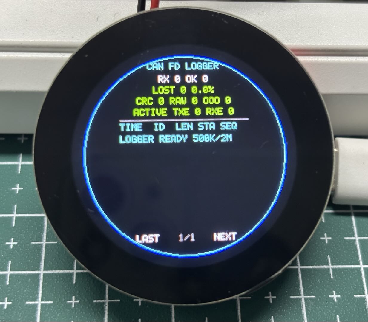
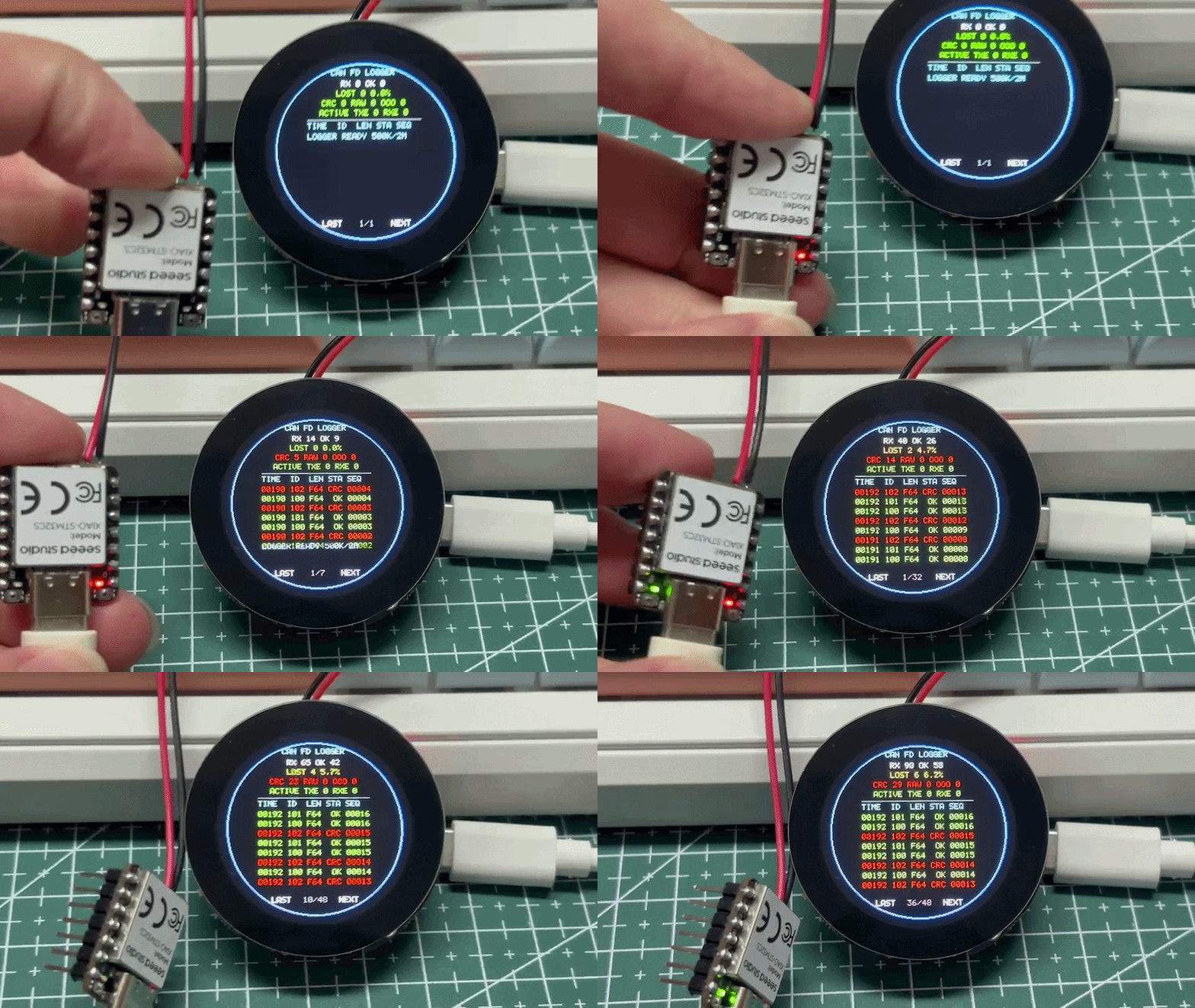
The following CAN FD fault simulation and visual diagnosis demo is built with two XIAO STM32C5 boards and a Round Display. It can generate normal frames, frames with missing sequences and frames with application-layer CRC errors. It also displays reception statistics in real time, estimates packet loss rate and shows check results.
Hardware Preparation
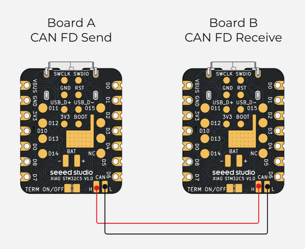
Two XIAO STM32C5 boards are required here. One acts as the CAN Logger for control and analysis, while the other simulates a CAN BUS node to transmit data and emulate packet loss. Connect the two boards via CAN_H and CAN_L. If the boards use separate power supplies, connect their grounds as well.
| Seeed Studio XIAO STM32C5 × 2 | Round Display for Seeed Studio XIAO |
|---|---|
|  |
Software Preparation
CANFD Send Message Node
- Use one XIAO STM32C5 as the CAN FD transmitting node.
- Arbitration phase bitrate: 500 kbit/s
- Data phase bitrate: 2 Mbit/s
- Payload length: 64 bytes
- Enable CAN FD and BRS
- The data contains sequence number, uptime, test payload and CRC16-CCITT
- Modify the device tree file
app.overlay
app.overlay
- Modify
prj.confto enable the corresponding configurations.
prj.conf
CONFIG_GPIO=y
CONFIG_SERIAL=y
CONFIG_CONSOLE=y
CONFIG_UART_CONSOLE=y
CONFIG_PRINTK=y
CONFIG_USB_DEVICE_STACK_NEXT=y
CONFIG_USBD_CDC_ACM_CLASS=y
CONFIG_UART_LINE_CTRL=y
CONFIG_UF2_DFU_RESET=y
CONFIG_CAN=y
CONFIG_CAN_FD_MODE=y
CONFIG_CAN_INIT_PRIORITY=80
CONFIG_CAN_DEFAULT_BITRATE=500000
CONFIG_CAN_DEFAULT_BITRATE_DATA=2000000
CONFIG_MAIN_STACK_SIZE=4096
- Write the program in
main.c. The project cyclically transmits three types of data frames:0x100: Normal data Continuous sequence numbers with valid application-layer CRC16.0x101: Frame loss simulation data Certain sequence numbers are intentionally skipped, so the receiver can estimate the number of lost frames based on sequence gaps.0x102: Checksum error data The frame is transmitted normally, but the application-layer CRC16 within the payload is deliberately tampered with for the receiver to detect CRC faults.
main.c
/* SPDX-License-Identifier: Apache-2.0
 * XIAO STM32C5 CAN FD logger traffic generator.
 */

#include <stdbool.h>
#include <stdint.h>
#include <string.h>
#include <zephyr/device.h>
#include <zephyr/drivers/can.h>
#include <zephyr/drivers/gpio.h>
#include <zephyr/kernel.h>
#include <zephyr/sys/printk.h>

#define CAN_NOMINAL_BITRATE 500000U
#define CAN_DATA_BITRATE    2000000U
#define PERIOD_MS           200U
#define FRAME_BYTES         64U
#define ID_NORMAL           0x100U
#define ID_LOSSY            0x101U
#define ID_BAD_CRC          0x102U
#define PACKET_MAGIC_0      0xCAU
#define PACKET_MAGIC_1      0xFDU
#define PACKET_VERSION      1U

enum packet_type { PACKET_NORMAL, PACKET_LOSSY, PACKET_BAD_CRC };

static const struct device *const can_dev =
	DEVICE_DT_GET(DT_CHOSEN(zephyr_canbus));
static const struct gpio_dt_spec led =
	GPIO_DT_SPEC_GET_OR(DT_ALIAS(led0), gpios, { 0 });
static uint32_t tx_ok;
static uint32_t tx_failed;

static uint16_t crc16_ccitt(const uint8_t *data, size_t len)
{
	uint16_t crc = 0xffffU;
	for (size_t i = 0; i < len; ++i) {
		crc ^= (uint16_t)data[i] << 8;
		for (int bit = 0; bit < 8; ++bit) {
			crc = (crc & 0x8000U) != 0U ?
				(uint16_t)((crc << 1) ^ 0x1021U) : (uint16_t)(crc << 1);
		}
	}
	return crc;
}

static void put_u32_le(uint8_t *dst, uint32_t value)
{
	dst[0] = (uint8_t)value;
	dst[1] = (uint8_t)(value >> 8);
	dst[2] = (uint8_t)(value >> 16);
	dst[3] = (uint8_t)(value >> 24);
}

static void build_packet(struct can_frame *frame, uint32_t id,
			 enum packet_type type, uint32_t sequence, bool corrupt_crc)
{
	memset(frame, 0, sizeof(*frame));
	frame->id = id;
	frame->flags = CAN_FRAME_FDF | CAN_FRAME_BRS;
	frame->dlc = can_bytes_to_dlc(FRAME_BYTES);
	frame->data[0] = PACKET_MAGIC_0;
	frame->data[1] = PACKET_MAGIC_1;
	frame->data[2] = PACKET_VERSION;
	frame->data[3] = (uint8_t)type;
	put_u32_le(&frame->data[4], sequence);
	put_u32_le(&frame->data[8], k_uptime_get_32());
	for (uint8_t i = 12U; i < FRAME_BYTES - 2U; ++i) {
		frame->data[i] = (uint8_t)(sequence + id + i * 17U);
	}
	uint16_t crc = crc16_ccitt(frame->data, FRAME_BYTES - 2U);
	if (corrupt_crc) {
		crc ^= 0x0001U;
	}
	frame->data[FRAME_BYTES - 2U] = (uint8_t)crc;
	frame->data[FRAME_BYTES - 1U] = (uint8_t)(crc >> 8);
}

static int send_packet(uint32_t id, enum packet_type type,
		       uint32_t sequence, bool corrupt_crc)
{
	struct can_frame frame;
	build_packet(&frame, id, type, sequence, corrupt_crc);
	int ret = can_send(can_dev, &frame, K_MSEC(100), NULL, NULL);
	if (ret == 0) {
		tx_ok++;
	} else {
		tx_failed++;
		printk("TX failed id=0x%03x seq=%u err=%d\n", id, sequence, ret);
	}
	return ret;
}

int main(void)
{
	uint32_t normal_seq = 0U, lossy_seq = 0U, bad_crc_seq = 0U;
	int ret;

	printk("XIAO STM32C5 CAN FD traffic generator\n");
	printk("nominal=%u data=%u payload=%u bytes BRS=on\n",
	       CAN_NOMINAL_BITRATE, CAN_DATA_BITRATE, FRAME_BYTES);
	if (!device_is_ready(can_dev)) {
		printk("CAN device is not ready\n");
		return -ENODEV;
	}
	if (led.port != NULL && gpio_is_ready_dt(&led)) {
		(void)gpio_pin_configure_dt(&led, GPIO_OUTPUT_INACTIVE);
	}
	ret = can_set_mode(can_dev, CAN_MODE_FD);
	if (ret != 0) {
		printk("Cannot enable CAN FD mode: %d\n", ret);
		return ret;
	}
	ret = can_set_bitrate(can_dev, CAN_NOMINAL_BITRATE);
	if (ret != 0) {
		printk("Cannot set nominal bitrate: %d\n", ret);
		return ret;
	}
	ret = can_set_bitrate_data(can_dev, CAN_DATA_BITRATE);
	if (ret != 0) {
		printk("Cannot set data bitrate: %d\n", ret);
		return ret;
	}
	ret = can_start(can_dev);
	if (ret != 0) {
		printk("Cannot start CAN controller: %d\n", ret);
		return ret;
	}
	printk("0x100 normal, 0x101 skips every 5th, 0x102 has bad app CRC16\n");

	while (true) {
		(void)send_packet(ID_NORMAL, PACKET_NORMAL, normal_seq++, false);
		if ((lossy_seq % 5U) != 4U) {
			(void)send_packet(ID_LOSSY, PACKET_LOSSY, lossy_seq, false);
		} else {
			printk("INTENTIONAL DROP id=0x101 seq=%u\n", lossy_seq);
		}
		lossy_seq++;
		(void)send_packet(ID_BAD_CRC, PACKET_BAD_CRC, bad_crc_seq++, true);
		if ((normal_seq % 10U) == 0U) {
			printk("TX ok=%u failed=%u seq=%u\n", tx_ok, tx_failed, normal_seq);
		}
		if (led.port != NULL) {
			(void)gpio_pin_toggle_dt(&led);
		}
		k_msleep(PERIOD_MS);
	}
}
CAN Logger Node
- Develop the CAN Logger firmware code using one XIAO STM32C5 together with the Round Display.
- Receive and parse 64-byte CAN FD test frames
- Verify frame type, payload length, protocol identifier and version
- Estimate lost frame count and frame loss rate from sequence number gaps
- Detect duplicated or out-of-order data
- Validate CRC16-CCITT in the payload
- Read CAN controller status and TX/RX error counters
- Use different colors to distinguish normal frames, lost frames, CRC errors and raw data
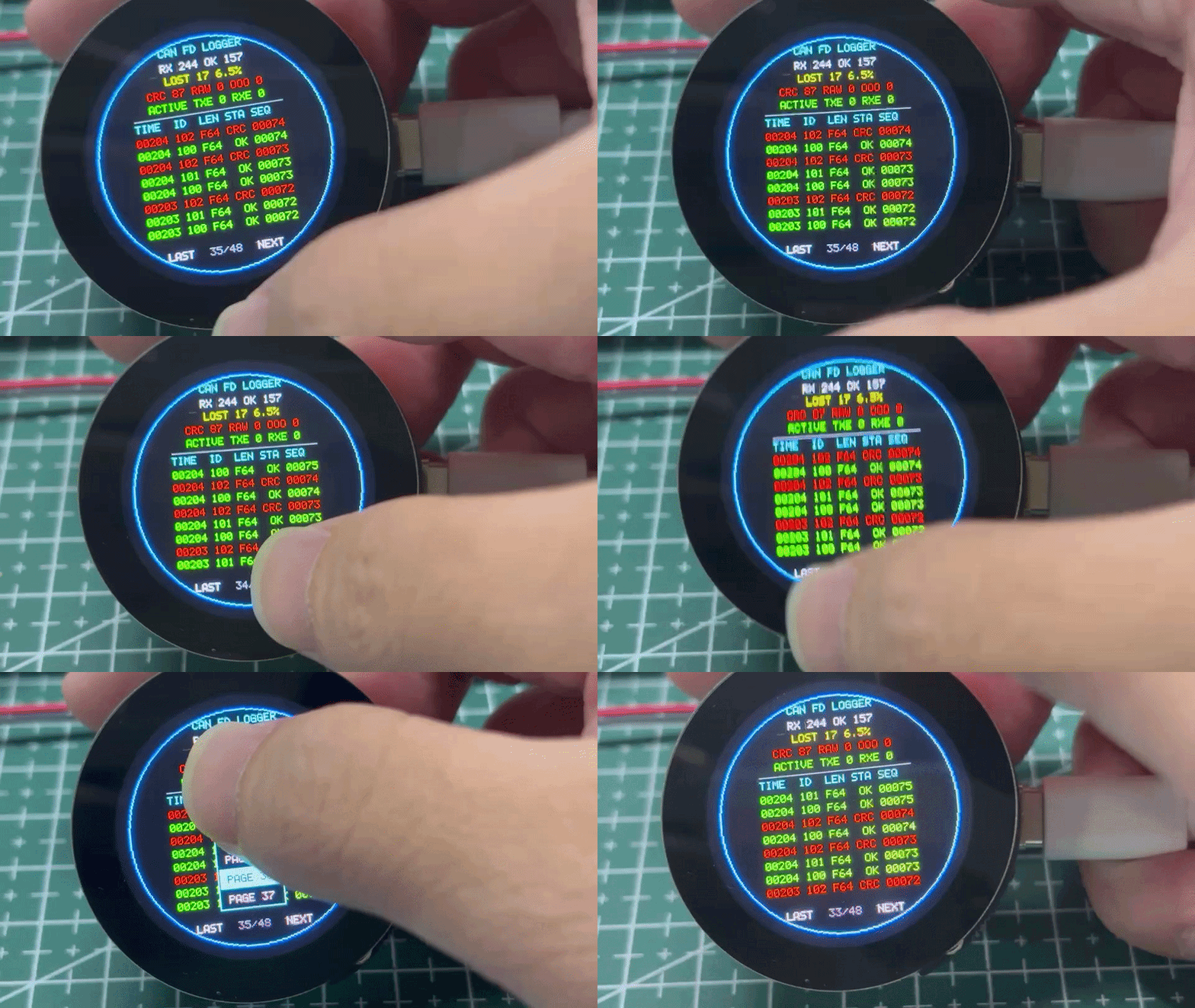
- Display statistics and the latest 48 in-memory log entries on the round screen
- Browse logs page by page via the bottom LAST / Page number / NEXT touch buttons
- Adopt the CHSC6X touch controller; read touch data over hardware I²C
- Modify the device tree file
app.overlayto bind the Round Display for Seeed Studio XIAO.
app.overlay
- Modify
prj.confto enable the corresponding configurations.
prj.conf
CONFIG_GPIO=y
CONFIG_I2C=y
CONFIG_I2C_STM32_BUS_RECOVERY=y
CONFIG_SPI=y
CONFIG_DISPLAY=y
CONFIG_MIPI_DBI=y
CONFIG_CAN=y
CONFIG_CAN_FD_MODE=y
CONFIG_CAN_INIT_PRIORITY=80
CONFIG_CAN_DEFAULT_BITRATE=500000
CONFIG_CAN_DEFAULT_BITRATE_DATA=2000000
CONFIG_SERIAL=y
CONFIG_CONSOLE=y
CONFIG_UART_CONSOLE=y
CONFIG_PRINTK=y
CONFIG_USB_DEVICE_STACK_NEXT=y
CONFIG_USBD_CDC_ACM_CLASS=y
CONFIG_UART_LINE_CTRL=y
CONFIG_UF2_DFU_RESET=y
CONFIG_MAIN_STACK_SIZE=6144
-
Write the program in
main.cand integrate the CAN FD analysis logic. Since the reference code is quite long, navigate to the code file and copy its contents intomain.c.- 📄[c-file] can-logger-main.c
Result
The transmitting node and logger node shall be wired by matching CAN_H to CAN_H and CAN_L to CAN_L.
- Display when no connection
- Display when nodes are connected
- Disconnect the transmitting node to view historical data
Summary
Through these simple application examples of the XIAO STM32C5, you should gain a basic understanding of its usage scenarios. Wish you a great experience with this tiny dev board and inspire more ideas to explore its application possibilities. You are also welcome to share your projects with the open-source community so everyone can see your work.
Tech Support & Product Discussion
Thank you for choosing our products! We are here to provide you with different support to ensure that your experience with our products is as smooth as possible. We offer several communication channels to cater to different preferences and needs.