XIAO STM32C5 CANFD Usage
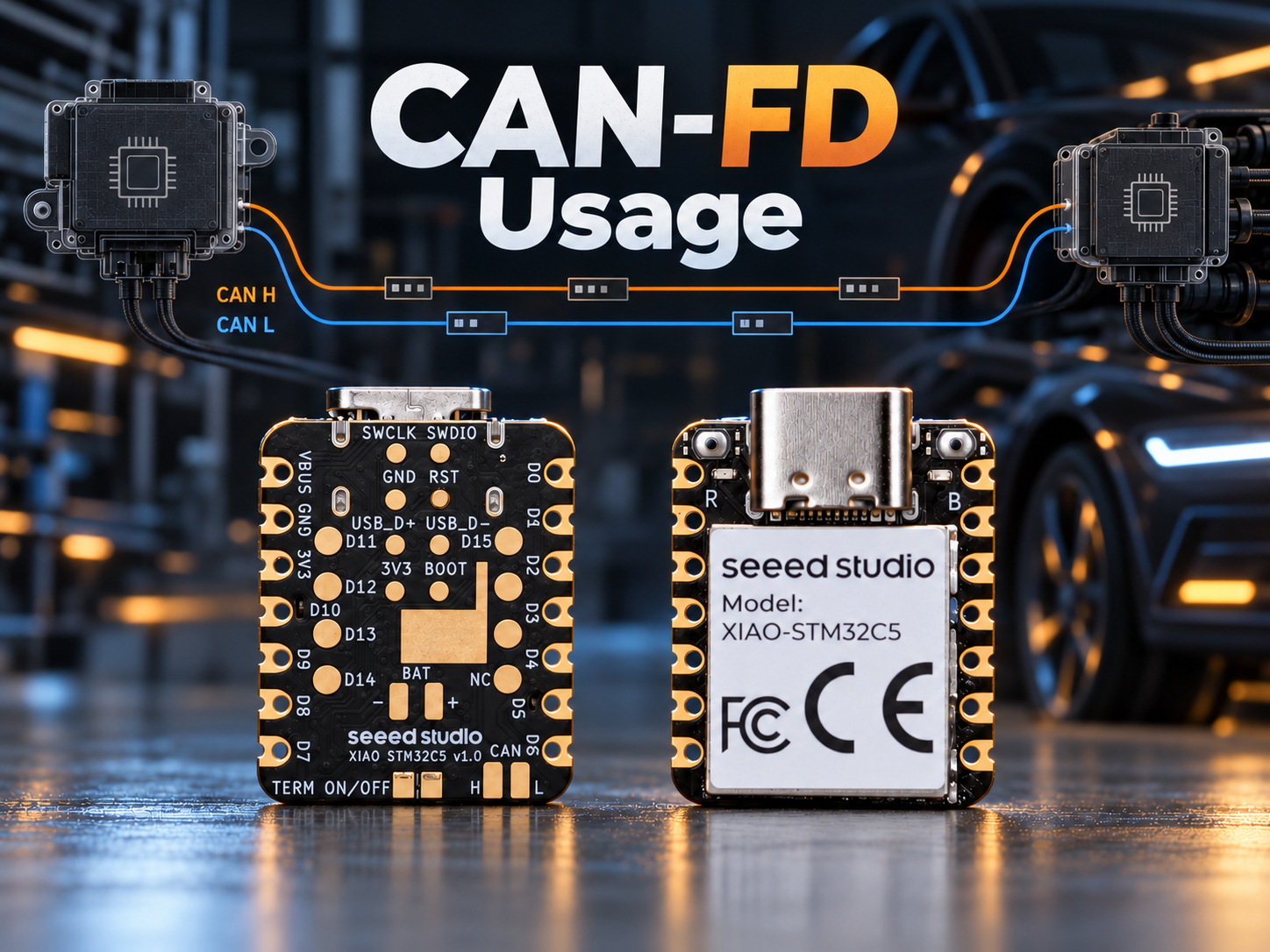
CAN Bus Introduction
CAN (Controller Area Network) is a serial communication bus developed by Bosch beginning in 1983 and publicly introduced in 1986. Initially designed for automotive electronics, it is now widely used in industrial automation, robotics, medical devices, and embedded systems.
The CAN data link layer and high-speed physical layer are defined by the ISO 11898 series of standards. In terms of the OSI model, CAN primarily specifies the following two layers:
- Physical layer: Defines cabling, electrical signaling, bit timing, and transceiver connections.
- Data link layer: Defines frame formats, bus arbitration, error detection, and fault confinement.
The main features of CAN include:
- Multi-master communication: When the bus is idle, any node can attempt to transmit without relying on polling by a dedicated master.
- Message-based broadcasting: Frames carry message identifiers rather than source and destination addresses. Each node uses filters to determine which messages to accept.
- Non-destructive arbitration: When multiple nodes transmit simultaneously, their identifiers are compared bit by bit, starting with the most significant bit. At the first differing bit, a dominant
0overrides a recessive1, giving the frame with the numerically lower identifier higher priority. Nodes that lose arbitration stop transmitting without corrupting the winning frame. - Robust error handling: CAN controllers can detect bit, stuffing, CRC, form, and ACK errors. Error counters and automatic retransmission improve communication reliability.
- Low wiring and component costs: High-speed CAN typically requires only one twisted pair, a transceiver for each node, and one termination resistor at each end of the bus.
CAN Physical Signaling
High-speed CAN typically uses a twisted pair consisting of CAN_H and CAN_L. The receiver determines the bus state from the differential voltage between the two signal lines:
V_diff = V(CAN_H) - V(CAN_L)
- Recessive bit
1: CAN_H and CAN_L are at similar voltage levels, producing a differential voltage close to 0 V. For common 5 V high-speed CAN transceivers, both lines are typically near 2.5 V. - Dominant bit
0: The CAN_H voltage rises while the CAN_L voltage falls. For common 5 V high-speed CAN transceivers, the typical levels are approximately 3.5 V and 1.5 V, respectively, producing a differential voltage of about 2 V.
These are typical voltage values. Actual values depend on the transceiver, supply voltage, bus load, and common-mode voltage. Refer to the transceiver datasheet for the specified operating ranges.
On a CAN bus, a dominant 0 takes precedence over a recessive 1. This characteristic enables non-destructive bitwise arbitration and allows receiving nodes to acknowledge a correctly received frame by transmitting a dominant bit in the ACK slot.
Classic CAN Data Frame
The following Classical CAN 2.0A data frame is used as an example: identifier 0x00A, DLC 1, data 0x81, and CRC-15/CAN 0x18DA. The field labels, logic bits, and CAN_H/CAN_L waveforms are aligned by column.
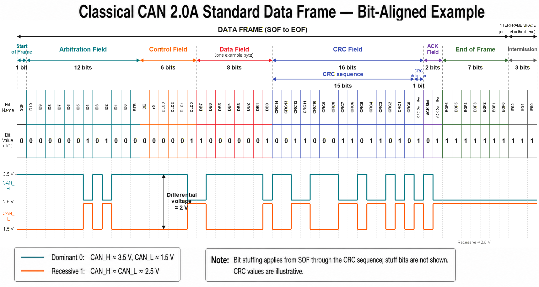
- Data Frame Fields
| Field | Length | Description |
|---|---|---|
| SOF | 1 bit | A dominant 0 marks the start of a frame and synchronizes the nodes. |
| Identifier | 11 bits | Identifies the message and determines its arbitration priority. |
| RTR | 1 bit | Dominant 0 for a data frame; recessive 1 for a remote frame. |
| IDE | 1 bit | Dominant 0 for a standard frame; recessive 1 for an extended frame. |
| r0 | 1 bit | Reserved bit transmitted as a dominant 0. |
| DLC | 4 bits | Values from 0 to 8 specify a payload length of 0 to 8 bytes. In Classical CAN, values from 9 to 15 also represent an 8-byte payload. |
| Data | 0–8 bytes | Contains the payload specified by the DLC. |
| CRC sequence | 15 bits | Enables receiving nodes to detect transmission errors. |
| CRC delimiter | 1 bit | Fixed at recessive 1. |
| ACK slot | 1 bit | The transmitter sends a recessive 1; nodes that receive the frame without error overwrite it with a dominant 0. |
| ACK delimiter | 1 bit | Fixed at recessive 1. |
| EOF | 7 bits | Seven consecutive recessive bits mark the end of the frame. |
| Intermission | 3 bits | Three recessive bits following the frame; part of the interframe space rather than the frame itself. |
How a CAN Frame Is Transmitted
- After detecting that the bus is idle, the transmitting node starts the frame with the SOF bit.
- If multiple nodes begin transmitting simultaneously, they compare the bus state bit by bit during the arbitration field. A node that transmits a recessive
1but detects a dominant0loses arbitration and stops transmitting. - The winning node continues transmitting the control and data fields. Receiving nodes filter the frame by its identifier and determine the payload length from the DLC.
- The receiving nodes remove stuff bits and verify the CRC. If the frame format and CRC are valid, they transmit a dominant
0in the ACK slot. - The transmitting node completes the transmission after detecting the ACK. If no ACK is detected, it reports an ACK error and normally attempts retransmission according to the controller configuration.
Bit Stuffing
From the SOF through the end of the CRC sequence, the transmitter inserts one complementary stuff bit after five consecutive bits of the same logical value. The receiver removes these stuff bits automatically.
Bit stuffing provides signal edges for synchronization and assists with error detection. Stuff bits do not belong to any frame field and are not included in the DLC or the specified field lengths. Therefore, the actual transmission time depends on the bit rate, payload length, and number of inserted stuff bits.
Introduction to CAN FD
Classical CAN supports a maximum payload of 8 bytes and a nominal bit rate of up to 1 Mbit/s. To support larger data transfers, Bosch introduced CAN FD (CAN with Flexible Data-rate) in 2012.
The main improvements include:
- Increasing the maximum payload from 8 bytes to 64 bytes per frame.
- Using the BRS bit to switch to a higher bit rate during the data phase and return to the nominal bit rate before the ACK field.
- Using 17-bit or 21-bit CRC sequences, depending on the payload length, and introducing a new DLC-to-payload-length mapping.
- Retaining the message identifiers and bitwise arbitration mechanism of Classical CAN during the arbitration phase.
The achievable CAN FD data-phase bit rate depends on the controller, transceiver, clock accuracy, cable length, number of nodes, and network topology. Common data-phase bit rates include 2 Mbit/s, 5 Mbit/s, and higher.
Using CAN FD with PlatformIO
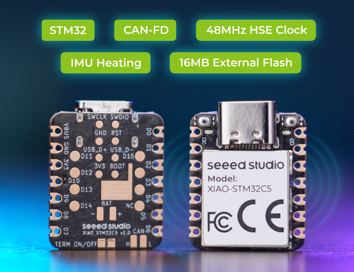
The XIAO STM32C5 provides a CAN FD interface with an onboard transceiver and termination resistor, allowing direct connection through CAN_H and CAN_L.
This example uses PlatformIO and the Zephyr framework with two XIAO STM32C5 boards:
- Board A transmits CAN FD frames.
- Board B receives and processes the frames, then controls its onboard user LED according to the received data.
This example uses PlatformIO. If you are not familiar with it, see Getting Started with PlatformIO for XIAO STM32C5.
- Check the hardware pin resources for CAN peripheral.
The XIAO STM32C5 provides two CAN FD interfaces. One exposes logic-level TX and RX signals for connection to an external CAN transceiver. The other is connected to the onboard TCAN3403-Q1 CAN FD transceiver and provides direct bus access through CAN_H and CAN_L.
The onboard CAN FD circuit includes a disconnectable 120 Ω termination resistor. Enable the resistor when the board is located at either end of the bus, and disconnect it when the board is an intermediate node or when another 120 Ω resistor is already installed at the XIAO end of the bus. The transceiver also supports standby mode to reduce power consumption when CAN communication is not required.
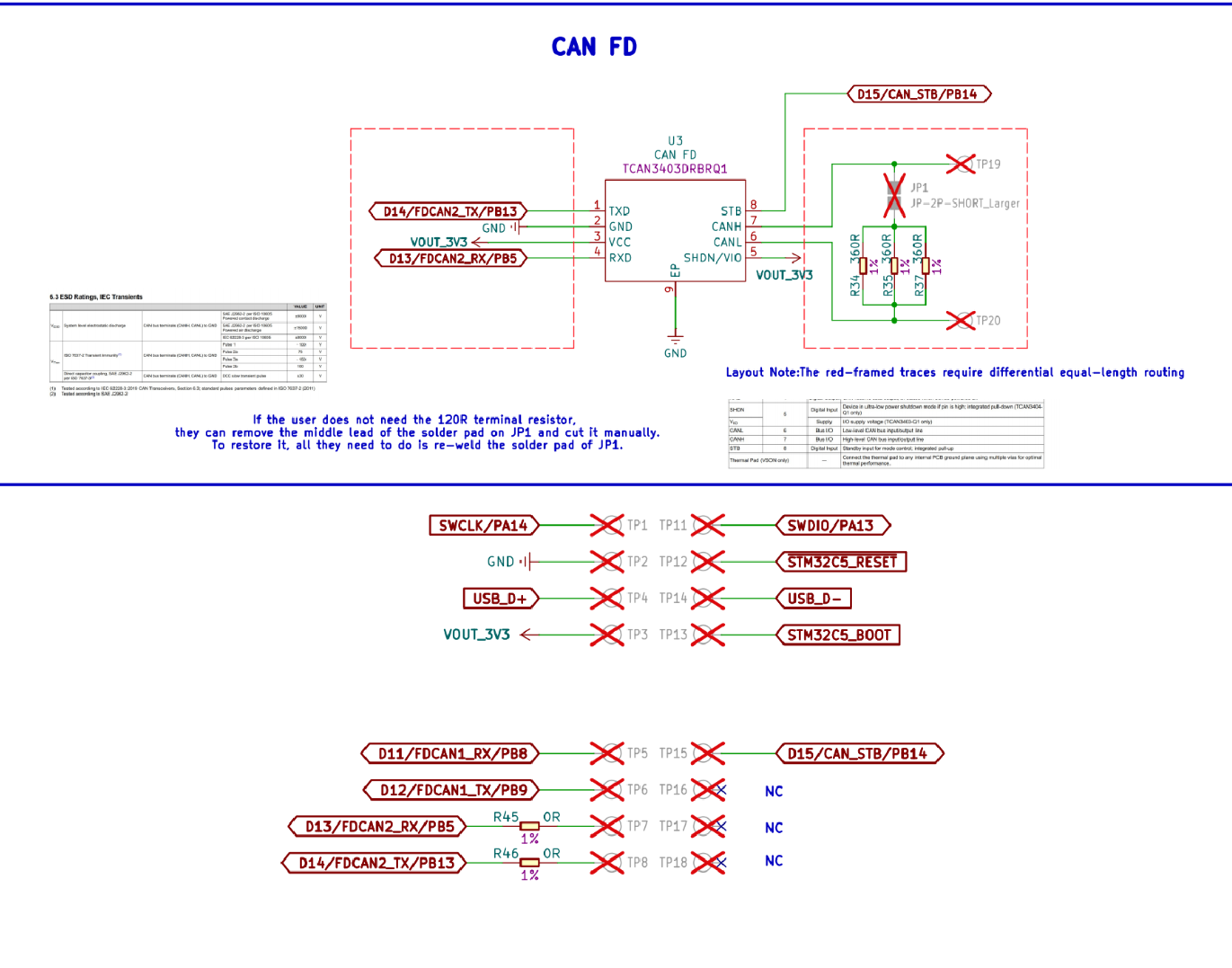
The CAN_H and CAN_L pads on the back can be used directly. However, if circular pads are used, an independent CAN conversion chip and matching terminal resistors need to be employed.
- Modify the
app.overlaydevicetree file. On XIAO STM32C5, thecanfd2node is used. The CAN transmit/receive pins are FDCAN2_RX‑PB5 and FDCAN2_TX‑PB13, with CAN_STB‑PB14. The corresponding devicetree alias nodes arefdcan2_rx_pb5,fdcan2_tx_pb13andcan_phy0.
/* FDCAN2, transceiver standby, and USB CDC are configured by the board DTS. */
- Modify the configuration file and add relevant configurations for
fdcan2.
# CAN FD: 500 kbit/s arbitration and 2 Mbit/s data phases.
CONFIG_CAN=y
CONFIG_CAN_FD_MODE=y
CONFIG_CAN_DEFAULT_BITRATE=500000
CONFIG_CAN_DEFAULT_BITRATE_DATA=2000000

# Keep application status output enabled; the board routes it to USB CDC.
CONFIG_PRINTK=y
- Write the
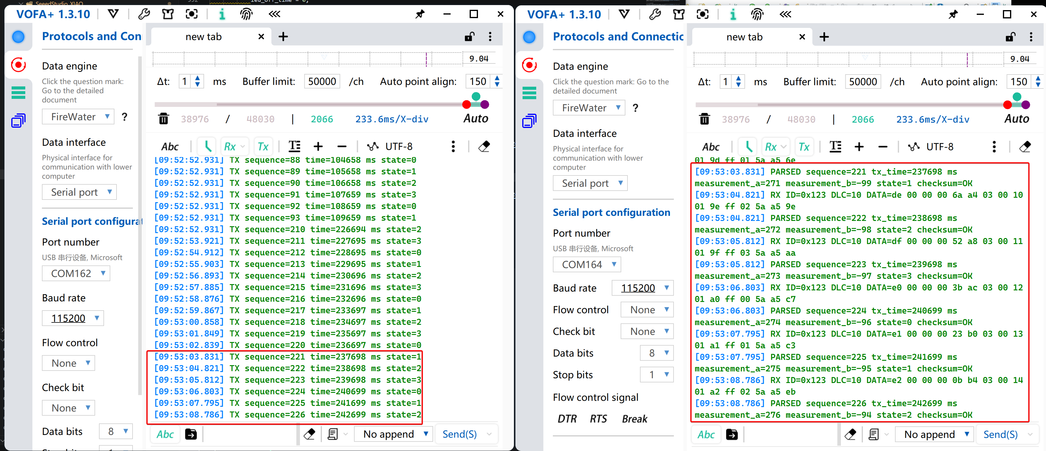
main.cprogram. This example uses two XIAO STM32C5 boards. Board A acts as the transmitter to send CAN protocol data. Board B works as the receiver; it receives and parses CAN messages, then turns on the on‑board LED.
CANFD Send Program
/*
 * XIAO STM32C5 CAN FD sender (board A)
 *
 * Sends one 16-byte CAN FD frame with standard ID 0x123 over FDCAN2
 * every second. BRS uses 500 kbit/s for arbitration and 2 Mbit/s for
 * the data phase. Transmission status is printed through USB CDC ACM.
 */
#include <zephyr/device.h>
#include <zephyr/devicetree.h>
#include <zephyr/drivers/can.h>
#include <zephyr/kernel.h>

#include <stdint.h>

#define CAN_NODE DT_CHOSEN(zephyr_canbus)
#define CAN_ID 0x123U
#define CAN_DATA_LENGTH 16U
#define CAN_DATA_DLC 10U
#define SEND_PERIOD_MS 1000

static const struct device *const can_dev = DEVICE_DT_GET(CAN_NODE);

/* Encode multibyte fields explicitly as little-endian wire data. */
static void put_u16_le(uint8_t *dst, uint16_t value)
{
 dst[0] = (uint8_t)value;
 dst[1] = (uint8_t)(value >> 8);
}

static void put_u32_le(uint8_t *dst, uint32_t value)
{
 dst[0] = (uint8_t)value;
 dst[1] = (uint8_t)(value >> 8);
 dst[2] = (uint8_t)(value >> 16);
 dst[3] = (uint8_t)(value >> 24);
}

static uint8_t payload_checksum(const uint8_t *data)
{
 uint8_t checksum = 0U;

 for (size_t i = 0U; i < CAN_DATA_LENGTH - 1U; i++) {
  checksum ^= data[i];
 }

 return checksum;
}

/*
 * 16-byte application payload:
 *   [0..3]   sequence number (uint32, little-endian)
 *   [4..7]   sender uptime in milliseconds (uint32, little-endian)
 *   [8..9]   example measurement A (int16, little-endian)
 *   [10..11] example measurement B (int16, little-endian)
 *   [12]     state value cycling from 0 to 3
 *   [13..14] fixed markers 0x5A and 0xA5
 *   [15]     XOR checksum of bytes 0 through 14
 */
static void build_frame(struct can_frame *frame, uint32_t sequence)
{
 int16_t measurement_a = (int16_t)(250 + (sequence % 50U));
 int16_t measurement_b = (int16_t)(-100 + (sequence % 20U));

 *frame = (struct can_frame) {
  .id = CAN_ID,
  .dlc = CAN_DATA_DLC,
  /* FDF selects CAN FD; BRS enables the faster data phase. */
  .flags = CAN_FRAME_FDF | CAN_FRAME_BRS,
 };

 put_u32_le(&frame->data[0], sequence);
 put_u32_le(&frame->data[4], k_uptime_get_32());
 put_u16_le(&frame->data[8], (uint16_t)measurement_a);
 put_u16_le(&frame->data[10], (uint16_t)measurement_b);
 frame->data[12] = (uint8_t)(sequence & 0x03U);
 frame->data[13] = 0x5AU;
 frame->data[14] = 0xA5U;
 frame->data[15] = payload_checksum(frame->data);
}

int main(void)
{
 uint32_t sequence = 0U;
 int ret;

 if (!device_is_ready(can_dev)) {
  printk("FDCAN2 device is not ready\r\n");
  return 0;
 }

 /* The controller mode must be selected before the controller starts. */
 ret = can_set_mode(can_dev, CAN_MODE_FD);
 if (ret != 0) {
  printk("Failed to enable CAN FD mode: %d\r\n", ret);
  return 0;
 }

 ret = can_start(can_dev);
 if (ret != 0) {
  printk("Failed to start FDCAN2: %d\r\n", ret);
  return 0;
 }

 printk("FDCAN2 sender started: ID=0x%03x, 500 kbit/s + 2 Mbit/s data\r\n",
        CAN_ID);

 while (true) {
  struct can_frame frame;

  build_frame(&frame, sequence);
  /* A NULL callback makes this synchronous, with a 100 ms timeout. */
  ret = can_send(can_dev, &frame, K_MSEC(100), NULL, NULL);
  if (ret == 0) {
   printk("TX sequence=%u time=%u ms state=%u\r\n",
          sequence, k_uptime_get_32(), frame.data[12]);
   sequence++;
  } else {
   printk("FDCAN2 send failed: %d\r\n", ret);
  }

  k_msleep(SEND_PERIOD_MS);
 }

 return 0;
}
CAN Receive Program
/*
 * XIAO STM32C5 CAN FD receiver (board B)
 *
 * FDCAN2 accepts standard ID 0x123, decodes the 16-byte application
 * payload, and prints it through USB CDC ACM. A valid frame lights the
 * onboard LED for 100 ms. With no traffic, the LED stays off and a
 * timeout warning is printed once per second.
 */
#include <zephyr/device.h>
#include <zephyr/devicetree.h>
#include <zephyr/drivers/can.h>
#include <zephyr/drivers/gpio.h>
#include <zephyr/kernel.h>

#include <stdint.h>

#define CAN_NODE DT_CHOSEN(zephyr_canbus)
#define CAN_ID 0x123U
#define CAN_DATA_LENGTH 16U
#define CAN_DATA_DLC 10U
#define LED_FLASH_MS 100
#define RX_POLL_MS 20
#define NO_RX_REPORT_MS 1000

static const struct device *const can_dev = DEVICE_DT_GET(CAN_NODE);
static const struct gpio_dt_spec led =
 GPIO_DT_SPEC_GET(DT_ALIAS(led0), gpios);

/* The driver posts frames from interrupt context; the main loop consumes them. */
CAN_MSGQ_DEFINE(rx_msgq, 10);

/* Decode multibyte fields using the sender's little-endian wire format. */
static uint16_t get_u16_le(const uint8_t *src)
{
 return (uint16_t)src[0] | ((uint16_t)src[1] << 8);
}

static uint32_t get_u32_le(const uint8_t *src)
{
 return (uint32_t)src[0] |
        ((uint32_t)src[1] << 8) |
        ((uint32_t)src[2] << 16) |
        ((uint32_t)src[3] << 24);
}

static uint8_t payload_checksum(const uint8_t *data)
{
 uint8_t checksum = 0U;

 for (size_t i = 0U; i < CAN_DATA_LENGTH - 1U; i++) {
  checksum ^= data[i];
 }

 return checksum;
}

/*
 * Print the raw payload and its decoded fields.
 * A true return value means the XOR checksum passed and permits an LED flash.
 */
static bool print_frame(const struct can_frame *frame)
{
 uint32_t sequence = get_u32_le(&frame->data[0]);
 uint32_t tx_time_ms = get_u32_le(&frame->data[4]);
 int16_t measurement_a = (int16_t)get_u16_le(&frame->data[8]);
 int16_t measurement_b = (int16_t)get_u16_le(&frame->data[10]);
 uint8_t state = frame->data[12];
 uint8_t received_checksum = frame->data[15];
 uint8_t calculated_checksum = payload_checksum(frame->data);

 printk("RX ID=0x%03x DLC=%u DATA=", frame->id, frame->dlc);
 for (size_t i = 0U; i < CAN_DATA_LENGTH; i++) {
  printk("%02x%s", frame->data[i],
         (i == CAN_DATA_LENGTH - 1U) ? "" : " ");
 }
 printk("\r\n");

 printk("PARSED sequence=%u tx_time=%u ms measurement_a=%d "
        "measurement_b=%d state=%u checksum=%s\r\n",
        sequence, tx_time_ms, measurement_a, measurement_b, state,
        received_checksum == calculated_checksum ? "OK" : "ERROR");

 return received_checksum == calculated_checksum;
}

int main(void)
{
 /* Match standard 11-bit ID 0x123; other IDs do not enter the queue. */
 const struct can_filter filter = {
  .id = CAN_ID,
  .mask = CAN_STD_ID_MASK,
  .flags = 0U,
 };
 int64_t led_off_time = 0;
 int64_t last_rx_time = k_uptime_get();
 int64_t last_no_rx_report_time = last_rx_time;
 int filter_id;
 int ret;

 if (!gpio_is_ready_dt(&led)) {
  printk("LED device is not ready\r\n");
  return 0;
 }

 /* GPIO_OUTPUT_INACTIVE honors devicetree polarity and starts with LED off. */
 ret = gpio_pin_configure_dt(&led, GPIO_OUTPUT_INACTIVE);
 if (ret != 0) {
  printk("Failed to configure LED: %d\r\n", ret);
  return 0;
 }

 if (!device_is_ready(can_dev)) {
  printk("FDCAN2 device is not ready\r\n");
  return 0;
 }

 /* Enable CAN FD mode before starting the controller. */
 ret = can_set_mode(can_dev, CAN_MODE_FD);
 if (ret != 0) {
  printk("Failed to enable CAN FD mode: %d\r\n", ret);
  return 0;
 }

 /* Queue matching frames so parsing and printing stay out of interrupt context. */
 filter_id = can_add_rx_filter_msgq(can_dev, &rx_msgq, &filter);
 if (filter_id < 0) {
  printk("Failed to add receive filter: %d\r\n", filter_id);
  return 0;
 }

 ret = can_start(can_dev);
 if (ret != 0) {
  printk("Failed to start FDCAN2: %d\r\n", ret);
  return 0;
 }

 printk("FDCAN2 receiver started: ID=0x%03x, output via USB CDC\r\n",
        CAN_ID);

 while (true) {
  struct can_frame frame;

  /*
   * Poll with a short timeout instead of blocking forever so the loop
   * can turn off the LED and report an absence of CAN traffic.
   */
  if (k_msgq_get(&rx_msgq, &frame, K_MSEC(RX_POLL_MS)) != 0) {
   int64_t now = k_uptime_get();

   if (led_off_time != 0 && now >= led_off_time) {
    (void)gpio_pin_set_dt(&led, 0);
    led_off_time = 0;
   }

   if ((now - last_rx_time) >= NO_RX_REPORT_MS &&
       (now - last_no_rx_report_time) >= NO_RX_REPORT_MS) {
    printk("WARN: no FDCAN2 data received for %lld ms\r\n",
           now - last_rx_time);
    last_no_rx_report_time = now;
   }
   continue;
  }

  last_rx_time = k_uptime_get();
  last_no_rx_report_time = last_rx_time;

  /* This example only decodes 16-byte CAN FD frames. */
  if ((frame.flags & CAN_FRAME_FDF) == 0U ||
      frame.dlc != CAN_DATA_DLC) {
   printk("Ignored non-matching frame: flags=0x%x dlc=%u\r\n",
          frame.flags, frame.dlc);
   (void)gpio_pin_set_dt(&led, 0);
   led_off_time = 0;
   continue;
  }

  if (print_frame(&frame)) {
   /* Logical GPIO levels automatically handle the active-low onboard LED. */
   (void)gpio_pin_set_dt(&led, 1);
   led_off_time = k_uptime_get() + LED_FLASH_MS;
  } else {
   (void)gpio_pin_set_dt(&led, 0);
   led_off_time = 0;
  }
 }

 return 0;
}
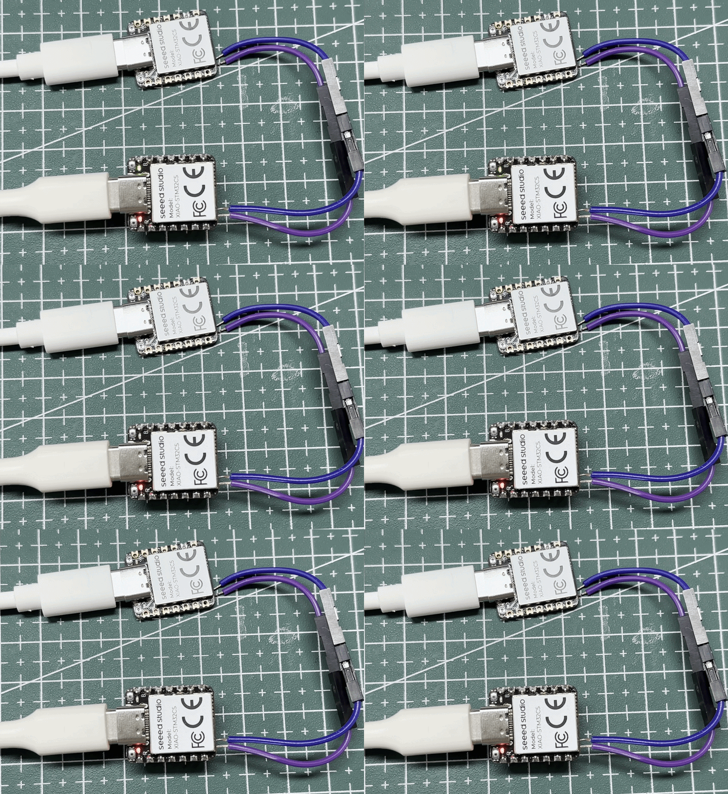
- Results are shown in the figure below.
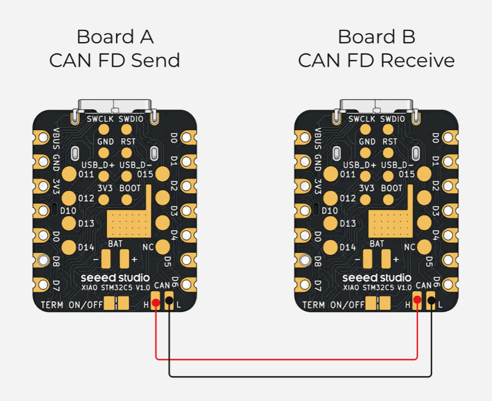
- Connect CAN_H to CAN_H and CAN_L to CAN_L between Boards A and B. If they use separate power supplies, connect their grounds as well. Board B blinks its LED after receiving and validating a frame.
- Check transmitted and parsed data using the serial monitor.
USB to CAN Bridge
The CAN Bridge turns the XIAO STM32C5 into a USB‑CAN adapter. It forwards messages bidirectionally between the PC and CAN/CAN‑FD bus, allowing the PC to send control commands, monitor device status, and log bus traffic. Typical use‑cases include robot joint motor debugging, automotive ECU and in‑vehicle network analysis, integration testing for industrial servos and CAN sensors, and BMS status monitoring. For robot development as an example, the PC can send enable, position and velocity commands to joint motor controllers via CAN Bridge, while receiving angle, current, temperature and fault information.
This tutorial provides two implementations: gs_usb and slcan. Both offer similar CAN‑side functions; the main differences lie in host‑board data transport, supported platforms, and CAN‑FD capability.
gs_usb vs slcan
gs_usb is a communication protocol for USB‑CAN adapters. The board transfers CAN messages over USB to the PC. On Linux, the in‑kernel gs_usb driver registers it directly as a SocketCAN interface such as can0. It delivers high throughput with CAN‑FD support, suited for high‑speed communication, bus monitoring, automated tests and long‑term debugging under Linux.
slcan is a communication method that encapsulates CAN messages with Lawicel ASCII commands. In this project, the board communicates with the PC over the USB CDC serial port. The board appears as a COM port on Windows and /dev/ttyACMx on Linux. It can work with SavvyCAN, python‑can or slcand. This approach features a simple protocol, flexible access and good cross‑platform compatibility.
Working with gs_usb
This section demonstrates functionality using pre‑built firmware. Source code can be downloaded from the platform‑seeedboards repository.
- The board has an onboard 120 Ω terminator. When it is enabled and the board is at one end of the bus, no additional resistor is needed at that end. Ensure the other end is also terminated; disable the onboard resistor for an intermediate node.
- This section is based on Ubuntu 22.04 LTS Linux distribution.
- 📄[Firmware] CAN-Bridge-gsusb Firmware
- Refer to the GitHub link for source code.
- Double‑press the Reset button on the XIAO STM32C5 to enter bootloader mode. Download and copy the firmware file to the
XIAOC5BOOTmass‑storage drive. To test CAN‑FD transmit and receive performance, flash the firmware onto two XIAO STM32C5 boards for verification.
Refer to the wiring diagram for connections. Using CANFD With PlatformIO
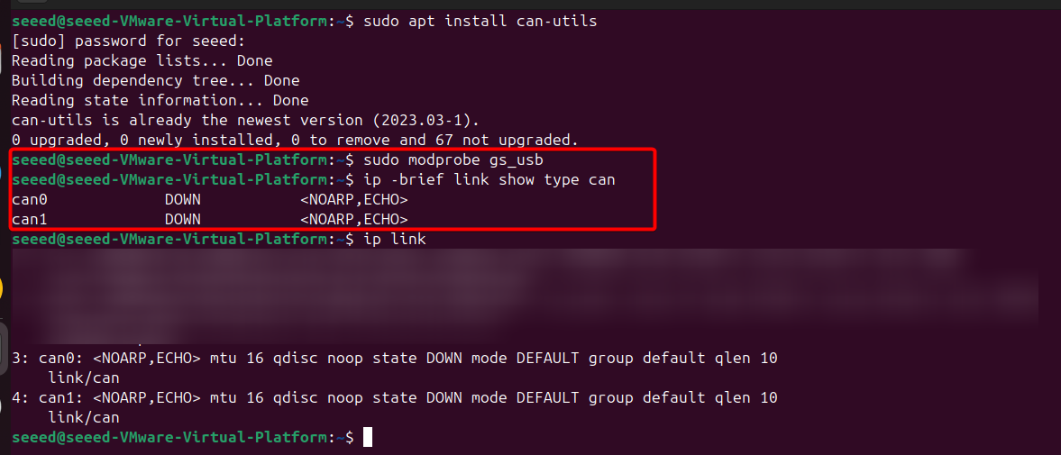
- Connect the board to your Linux host, open a terminal, and install the required software packages. The CAN devices will then be enumerated, typically
can0andcan1.
# Install can-utils
sudo apt update
sudo apt install can-utils

# Load gs_usb kernel module
sudo modprobe gs_usb
ip -brief link show type can
- Configure the CAN interfaces
# Bring up can0
sudo ip link set can0 down
sudo ip link set can0 type can bitrate 500000 dbitrate 2000000 fd on
sudo ip link set can0 up

# Bring up can1
sudo ip link set can1 down
sudo ip link set can1 type can bitrate 5000000 dbitrate 2000000 fd on
sudo ip link set can1 up
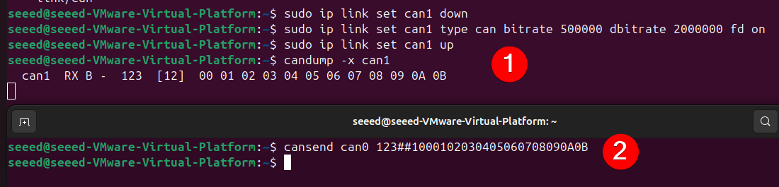
- Send and monitor CAN‑FD traffic
- Open another terminal to receive data on the
can1interface.
candump -x can1
- In another terminal, send a 12‑byte CAN‑FD frame with BRS enabled via the
can0interface.
cansend can0 123##1000102030405060708090A0B
- Verify with script
- Install the
python‑canmodule
sudo apt update
sudo apt install python3-can
- Run on the receiver side
canfd_2m_test.py
# SPDX-License-Identifier: Apache-2.0
"""Send or receive CAN FD frames at 500 kbit/s nominal and 2 Mbit/s data."""

import argparse
import time

import can

NOMINAL_BITRATE = 500_000
DATA_BITRATE = 2_000_000


def open_bus(interface, channel, serial_number=None, loop_back=False):
    if interface == "socketcan":
        options = {
            "interface": "socketcan",
            "channel": channel,
            "fd": True,
        }
    else:
        try:
            candle_channel = int(channel)
        except ValueError:
            candle_channel = channel
        options = {
            "interface": "candle",
            "channel": candle_channel,
            "fd": True,
            "bitrate": NOMINAL_BITRATE,
            "data_bitrate": DATA_BITRATE,
            "loop_back": loop_back,
            "ignore_config": True,
        }
        if serial_number:
            options["serial_number"] = serial_number
    return can.Bus(**options)


def make_test_frames():
    payload_12 = bytes(range(12))
    payload_64 = bytes(range(64))
    return (
        can.Message(
            arbitration_id=0x200,
            is_extended_id=False,
            is_fd=True,
            bitrate_switch=True,
            data=payload_12,
        ),
        can.Message(
            arbitration_id=0x201,
            is_extended_id=False,
            is_fd=True,
            bitrate_switch=True,
            data=payload_64,
        ),
    )


def send_frames(bus, count, interval):
    frames = make_test_frames()

    acknowledged = 0
    for _ in range(count):
        for frame in frames:
            try:
                bus.send(frame, timeout=1.0)
                acknowledged += 1
                print(
                    f"TX ID={frame.arbitration_id:#05x} len={len(frame.data)} "
                    f"FD={frame.is_fd} BRS={frame.bitrate_switch}"
                )
            except can.CanError as error:
                print(f"TX failed for ID {frame.arbitration_id:#05x}: {error}")
            time.sleep(interval)

    print(f"Transmission complete: {acknowledged} CAN FD frames submitted")


def loopback_test(bus, count, interval):
    frames = make_test_frames()
    passed = 0
    expected = count * len(frames)

    for _ in range(count):
        for frame in frames:
            bus.send(frame, timeout=1.0)
            deadline = time.monotonic() + 1.0
            received = None

            while time.monotonic() < deadline:
                candidate = bus.recv(timeout=0.1)
                if candidate is None:
                    continue
                if (
                    candidate.arbitration_id == frame.arbitration_id
                    and candidate.is_fd
                    and candidate.bitrate_switch
                    and bytes(candidate.data) == bytes(frame.data)
                ):
                    received = candidate
                    break

            if received is None:
                print(
                    f"FAIL ID={frame.arbitration_id:#05x}: "
                    "no matching loopback frame"
                )
            else:
                passed += 1
                print(
                    f"PASS ID={received.arbitration_id:#05x} "
                    f"len={len(received.data)} FD={received.is_fd} "
                    f"BRS={received.bitrate_switch}"
                )
            time.sleep(interval)

    print(f"Loopback complete: {passed}/{expected} CAN FD frames passed")
    if passed != expected:
        raise RuntimeError("CAN FD loopback test failed")


def receive_frames(bus, duration):
    deadline = time.monotonic() + duration
    received = 0
    while time.monotonic() < deadline:
        frame = bus.recv(timeout=0.5)
        if frame is None:
            continue
        received += 1
        print(
            f"RX ID={frame.arbitration_id:#x} len={len(frame.data)} "
            f"FD={frame.is_fd} BRS={frame.bitrate_switch} "
            f"data={bytes(frame.data).hex().upper()}"
        )
    print(f"Reception complete: {received} frames")


def main():
    parser = argparse.ArgumentParser(
        description="XIAO STM32C5 gs_usb CAN FD 500k/2M test"
    )
    parser.add_argument("mode", choices=("send", "receive", "loopback"))
    parser.add_argument(
        "--interface",
        choices=("candle", "socketcan"),
        default="candle",
        help="candle uses direct USB; socketcan uses a Linux canX interface",
    )
    parser.add_argument(
        "--channel",
        default="0",
        help="candle channel number or SocketCAN interface name such as can0",
    )
    parser.add_argument("--serial-number", help="USB serial number for board selection")
    parser.add_argument("--count", type=int, default=10)
    parser.add_argument("--interval", type=float, default=0.1)
    parser.add_argument("--duration", type=float, default=10.0)
    args = parser.parse_args()

    print(
        f"Opening {args.interface} channel {args.channel}: "
        f"nominal={NOMINAL_BITRATE}, "
        f"data={DATA_BITRATE}, FD enabled, "
        f"loopback={args.mode == 'loopback'}"
    )
    bus = open_bus(
        args.interface,
        args.channel,
        args.serial_number,
        loop_back=args.mode == "loopback",
    )
    try:
        if args.mode == "send":
            send_frames(bus, args.count, args.interval)
        elif args.mode == "receive":
            receive_frames(bus, args.duration)
        else:
            loopback_test(bus, args.count, args.interval)
    finally:
        bus.shutdown()


if __name__ == "__main__":
    main()
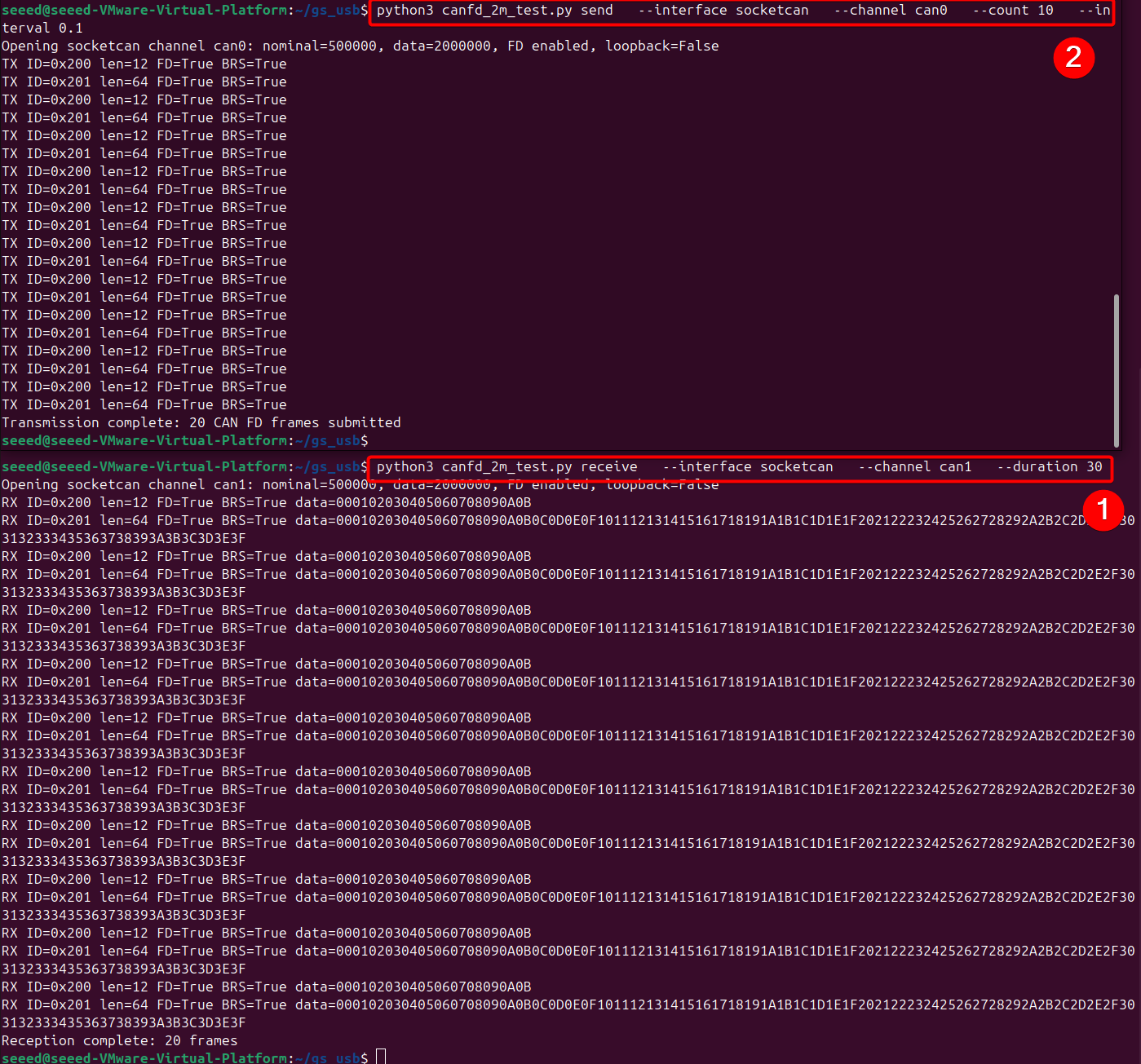
python3 canfd_2m_test.py receive \
  --interface socketcan \
  --channel can1 \
  --duration 30
- Run on the transmitter side
python3 canfd_2m_test.py send \
  --interface socketcan \
  --channel can0 \
  --count 10 \
  --interval 0.1
Working with slcan
This section demonstrates functionality using pre‑built firmware. Source code can be downloaded from the platform‑seeedboards repository.
- The XIAO STM32C5 already has a built-in 120 Ω CAN termination resistor enabled by default, so you do not need to solder an extra resistor across its CAN_H and CAN_L pads. When using two XIAO boards, the built-in resistor on each board terminates one end of the bus.
- This section is based on Ubuntu 22.04 LTS Linux distribution.
- 📄[Firmware] CAN-Bridge-slcan Firmware
- Refer to the GitHub link for source code.
- Double‑press the Reset button on the XIAO STM32C5 to enter bootloader mode. Download and copy the firmware file to the
XIAOC5BOOTmass‑storage drive. Use two XIAO STM32C5 boards with the firmware flashed, or one XIAO STM32C5 plus another slcan‑capable receiver device. - Connect the board to your Linux host and open a terminal. Locate the serial devices under
/dev/ttyACM*, typicallyttyACM0andttyACM1.
ls /dev/ttyACM*

- Install SavvyCAN. Download version V220 or newer, then establish a connection via SavvyCAN.
- For Linux systems, the
libfuse2package is required before use.
sudo apt update
sudo apt install libfuse2
- This example uses the V220 release. Run the application as shown below under Linux:
# For Linux
sudo chmod +x SavvyCAN-7c576c5-x86_64.AppImage
./SavvyCAN-7c576c5-x86_64.AppImage

# On Windows, directly launch the executable SavvyCAN.exe
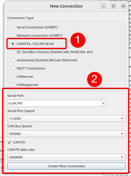
- Go to Connection → Open Connection Window. Click Add New Device Connection. Set connection type to LAWICEL / SLCAN Serial. Select
ttyACM0for Serial Port. Set Serial Port Speed to115200, CAN Bus Speed to500000 bit/s. Enable CAN‑FD, and set CAN‑FD data rate to2000000 bit/s.
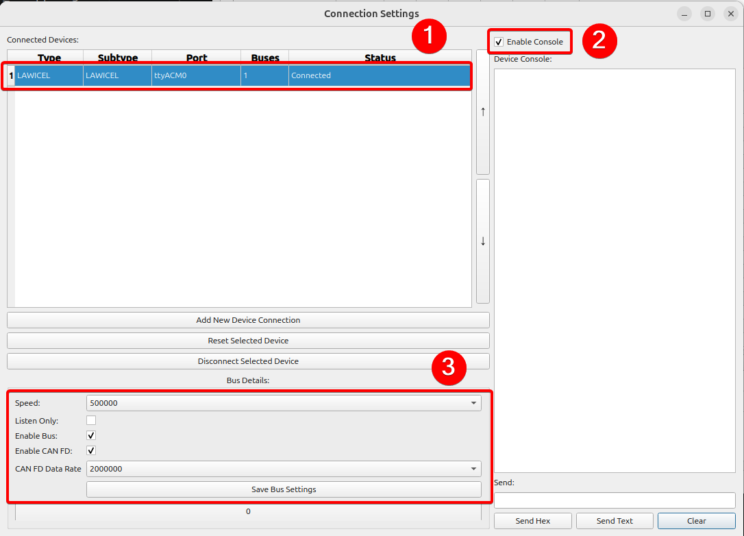
- After configuration, the connection status will indicate whether the connection succeeded. It is recommended to open the console in the upper‑right corner to view logs, verify that parameters match your settings, then save the configuration.
- Open a new terminal and run the test script. The script will automatically detect unused
/dev/ttyACM*serial devices and transmit CAN‑FD data.
python3 savvycan_fd_peer.py send
savvycan_fd_peer.py
# SPDX-License-Identifier: Apache-2.0
"""Send or receive SavvyCAN LAWICEL CAN FD frames with a second XIAO board."""

import argparse
import time

import serial
import serial.tools.list_ports

SEEED_VID = 0x2886
SERIAL_BAUD = 115200


def find_available_port(explicit_port=None):
    candidates = [explicit_port] if explicit_port else [
        port.device
        for port in serial.tools.list_ports.comports()
        if port.vid == SEEED_VID
    ]

    for device in candidates:
        try:
            connection = serial.Serial(device, SERIAL_BAUD, timeout=0.35)
            connection.dtr = True
            connection.rts = False
            time.sleep(0.4)
            connection.reset_input_buffer()
            return connection
        except (OSError, serial.SerialException) as error:
            print(f"Skipping {device}: {error}")

    raise RuntimeError(
        "No available Seeed CDC port. Close SavvyCAN on the peer port or "
        "specify the unused port with --port."
    )


def command(connection, text, response_wait=0.08):
    connection.reset_input_buffer()
    connection.write((text + "\r").encode("ascii"))
    connection.flush()
    time.sleep(response_wait)
    response = connection.read(256)
    if b"\x07" in response:
        raise RuntimeError(f"Firmware rejected command {text!r}: {response!r}")
    if b"\r" not in response:
        raise RuntimeError(f"No acknowledgement for {text!r}: {response!r}")
    return response


def open_can_fd(connection):
    command(connection, "C")
    command(connection, "S6")  # 500 kbit/s nominal bitrate
    command(connection, "Y2")  # 2 Mbit/s CAN FD data bitrate
    command(connection, "O")


def send_frames(connection, duration):
    frames = [
        "d2009000102030405060708090A0B",  # 12-byte standard FD, no BRS
        "b201F" + "".join(f"{value:02X}" for value in range(64)),
        "B001ABCDE9AABBCCDDEEFF001122334455",  # 12-byte extended FD with BRS
    ]
    deadline = time.monotonic() + duration
    sent = 0

    print("Sending IDs 0x200, 0x201, and 0x1ABCDE to SavvyCAN...")
    while time.monotonic() < deadline:
        for frame in frames:
            command(connection, frame, response_wait=0.04)
            sent += 1
            time.sleep(0.16)
    print(f"Transmission complete: {sent} acknowledged CAN FD frames.")


def receive_frames(connection, duration):
    deadline = time.monotonic() + duration
    print("Waiting for CAN FD frames sent by SavvyCAN...")
    connection.reset_input_buffer()
    while time.monotonic() < deadline:
        line = connection.read_until(b"\r")
        if line:
            print(line.decode("ascii", errors="replace").strip())


def main():
    parser = argparse.ArgumentParser()
    parser.add_argument("mode", choices=("send", "receive"))
    parser.add_argument(
        "--port",
        help="Unused peer port, for example COM4 or /dev/ttyACM1",
    )
    parser.add_argument("--duration", type=float, default=12.0)
    args = parser.parse_args()

    connection = find_available_port(args.port)
    print(f"Using {connection.port} at {SERIAL_BAUD} baud")
    try:
        open_can_fd(connection)
        if args.mode == "send":
            send_frames(connection, args.duration)
        else:
            receive_frames(connection, args.duration)
        command(connection, "C")
    finally:
        connection.close()


if __name__ == "__main__":
    main()
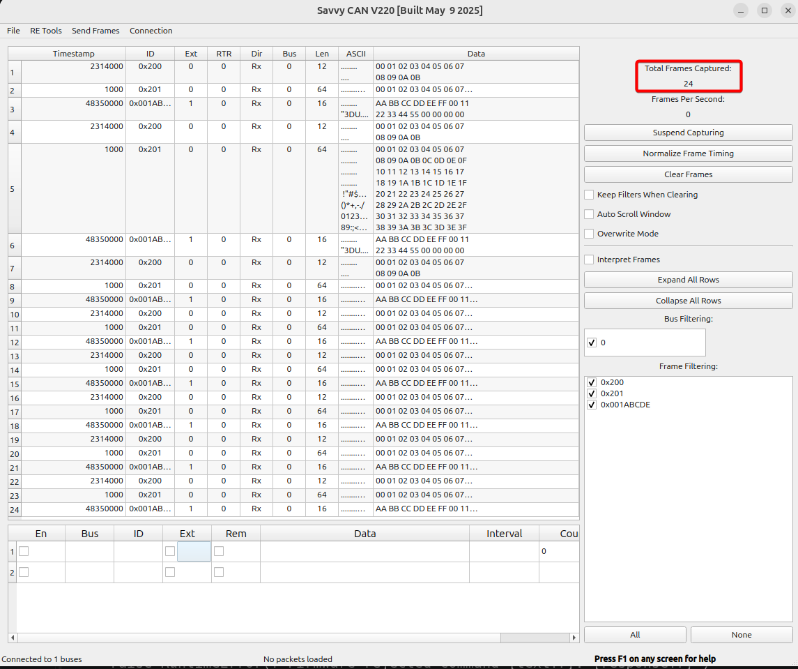
You can observe that the script writes 24 CAN‑FD frames to the /dev/ttyACM1 device. /dev/ttyACM0 shows busy because it is occupied by SavvyCAN.

- You can view the received and parsed CAN‑FD frame data on SavvyCAN’s main panel.
Drive a Motor Over CAN
The XIAO STM32C5 can serve as a driver mainboard for high‑precision brushless motors with CAN communication. It is suitable for practical applications in robot control, industrial control and multi‑motor control scenarios.
The following example demonstrates its driving capability by controlling the DM4310 motor.
This example is built with PlatformIO. If you are new to PlatformIO, please refer to Getting Started with PlatformIO For XIAO STM32C5
Hardware Preparation
- 1 × XIAO STM32C5
- PC with Type‑C cable
- 24 V power supply
- XT30 2+2 Power Separation Board
- DM4310 Motor
| Seeed Studio XIAO STM32C5 | DM4310 | XT30 2+2 Power Separation Board |
|---|---|---|
 |  |  |
Software Program
A 24 V power supply is required for motor driving. Use a compliant power supply to avoid hazards to your equipment and personal safety!
-
Obtain the motor ID. Use the Damiao host PC software to configure: Motor CAN ID:
0x007, Master ID:0x017. Please refer to Damiao 43 Series Motors Getting Started -
Flash the program via PlatformIO, or flash the pre‑built test firmware:
- 📄[Firmware] CAN-Driver-DM4310 Firmware
- Refer to the GitHub link for source code.
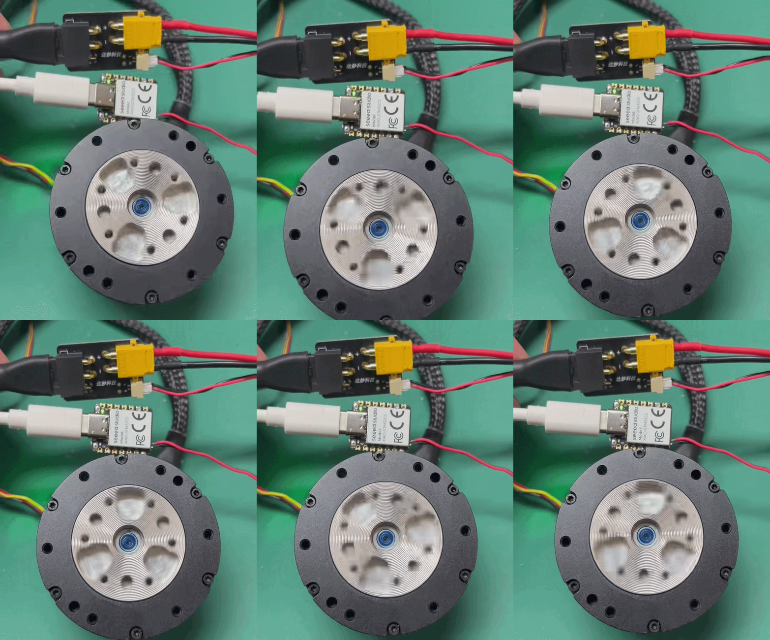
- After motor enable, the DM‑J4310 cycles through target velocities
0 → 3 → 6 → 10 → 6 → 3 rad/severy 5 seconds. The on‑board LED turns on when the target velocity is non‑zero and turns off when it is zero. Motor feedback data is printed over the serial port simultaneously.
- When driving the motor, ensure CAN_H and CAN_L on the XIAO STM32C5 are correctly matched with CAN_H and CAN_L of the connected device. Mismatched wiring will result in communication failure.
Summary
Following these examples, you should now have a basic understanding of how to use CAN‑FD features on the XIAO STM32C5. The payload transmitted over CAN varies for different use‑cases and depends on functional requirements. CAN and CAN‑FD are widely adopted in industrial control, embodied intelligence, robot control, automotive electronics and many other fields. Have fun building interesting projects with this feature, and share your work in the open‑source community for others to discover, learn from and reuse!
Reference source
Tech Support & Product Discussion
Thank you for choosing our products! We are here to provide you with different support to ensure that your experience with our products is as smooth as possible. We offer several communication channels to cater to different preferences and needs.