Getting Started with XIAO STM32C5
Overview
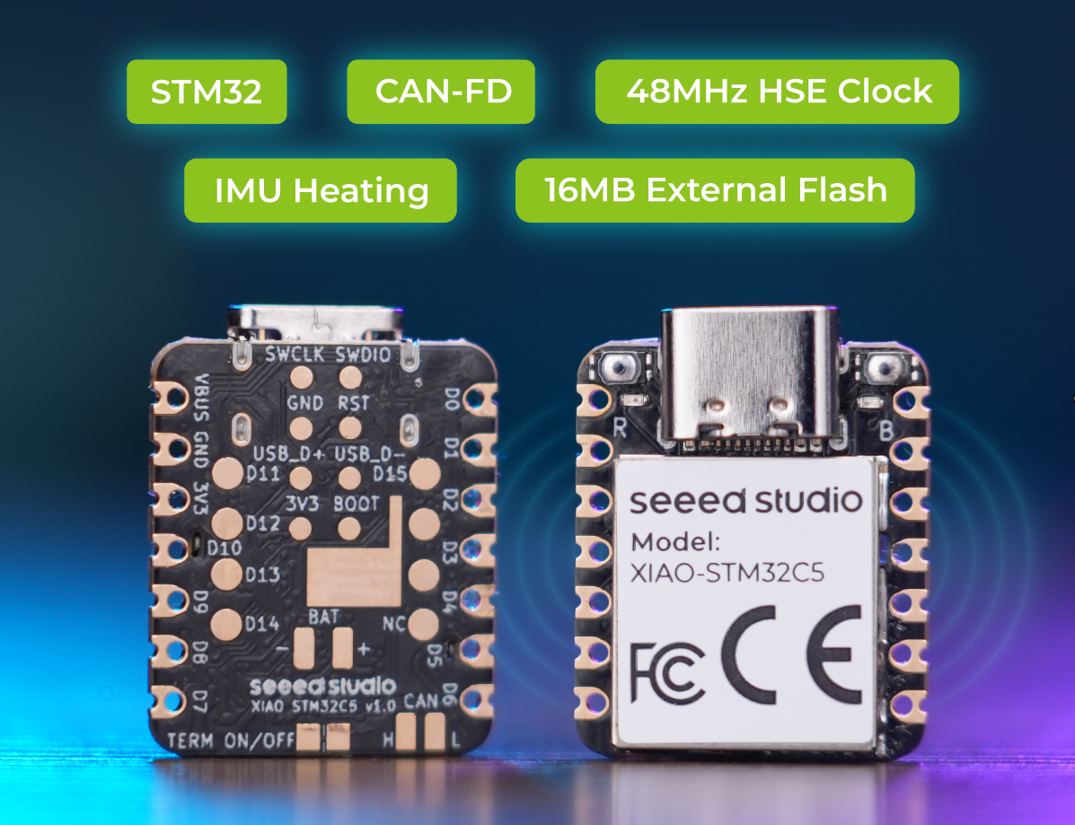
Meet the first STM32-powered XIAO. Built around the STM32C5A3CG with a 144MHz Arm Cortex-M33 core, XIAO STM32C5 brings CAN FD connectivity, 16MB of external Flash, and a six-axis IMU with programmable heating to the compact XIAO form factor. Dedicated heating resistors around the IMU enable firmware-controlled warm-up for robotics and motion-sensing projects. Two native CAN FD controllers, including one channel with an onboard TCAN3403-Q1 transceiver, provide a starting point for USB-to-CAN adapters, connected sensors, and robot control projects. USB-C and onboard battery charging support both desktop development and portable applications.
Features
- The First STM32-Powered XIAO: Built with the STM32C5A3CG, featuring a 144MHz Arm Cortex-M33 processor, floating-point support, and DSP instructions for embedded control and sensor processing.
- CAN FD Connectivity Built In: Two native CAN FD controllers, with one channel connected to an onboard TCAN3403-Q1 transceiver and accessible CANH/CANL pads. Add an external transceiver to use the second channel.
- 6-Axis IMU with Programmable Heating: The onboard LSM6DS3TR-C accelerometer and gyroscope are paired with dedicated heating resistors around the sensor. GPIO-controlled heating enables programmable warm-up and, with temperature-feedback firmware, closed-loop temperature regulation to help reduce temperature-related drift in robotics and motion-sensing applications.
- 16MB External Flash: Store application data, sensor logs, configuration files, and CAN message records using application firmware.
- External Crystal for Communication Timing: An onboard high-speed external crystal provides a clock reference for CAN FD and other timing-sensitive applications.
- USB-C and Battery Charging: Develop over USB-C or build battery-powered devices using the onboard lithium-battery charging circuit and battery connection pads.
- Compact, Integration-Friendly Design: The XIAO form factor and castellated edge pads support breadboard prototyping with headers and integration into custom carrier boards.
Specifications
| Item | Specification |
|---|---|
| Product | Seeed Studio XIAO STM32C5 |
| Microcontroller | STMicroelectronics STM32C5A3CG |
| CPU | Single-core Arm Cortex-M33, up to 144MHz, with FPU and DSP instructions |
| MCU package | UFQFPN48 |
| Internal program Flash | 1MB |
| SRAM | 256KB |
| External Flash | 16MB |
| CAN controllers | 2 native CAN FD controllers |
| Onboard CAN transceiver | 1 x TI TCAN3403-Q1 |
| Onboard CAN bus connection | CANH/CANL pads; use board GND as the signal reference |
| Second CAN channel | Digital TX/RX signals; external CAN transceiver required |
| CAN termination | 120 ohms, enabled by default; disconnectable through a cuttable solder link |
| CAN isolation | No onboard galvanic isolation |
| IMU | STMicroelectronics LSM6DS3TR-C, three-axis accelerometer and three-axis gyroscope |
| IMU heating | Dedicated heating resistors around the IMU with GPIO-controlled drive |
| Temperature regulation | Programmable warm-up; closed-loop setpoint regulation requires temperature feedback and suitable application firmware |
| External clock | Onboard high-speed external crystal |
| USB | USB-C; USB 2.0 Full Speed, 12Mbps signaling rate |
| Logic level | 3.3V |
| Power | USB-C 5V input or compatible lithium battery through BAT pads |
| Battery charging | Onboard charging circuit |
| User controls | Reset button and boot button |
| Indicators | User LED and charging indicator |
| Debug interface | SWD |
| Form factor | Compact XIAO module with castellated edge pads |
Hardware Overview
Pin Map
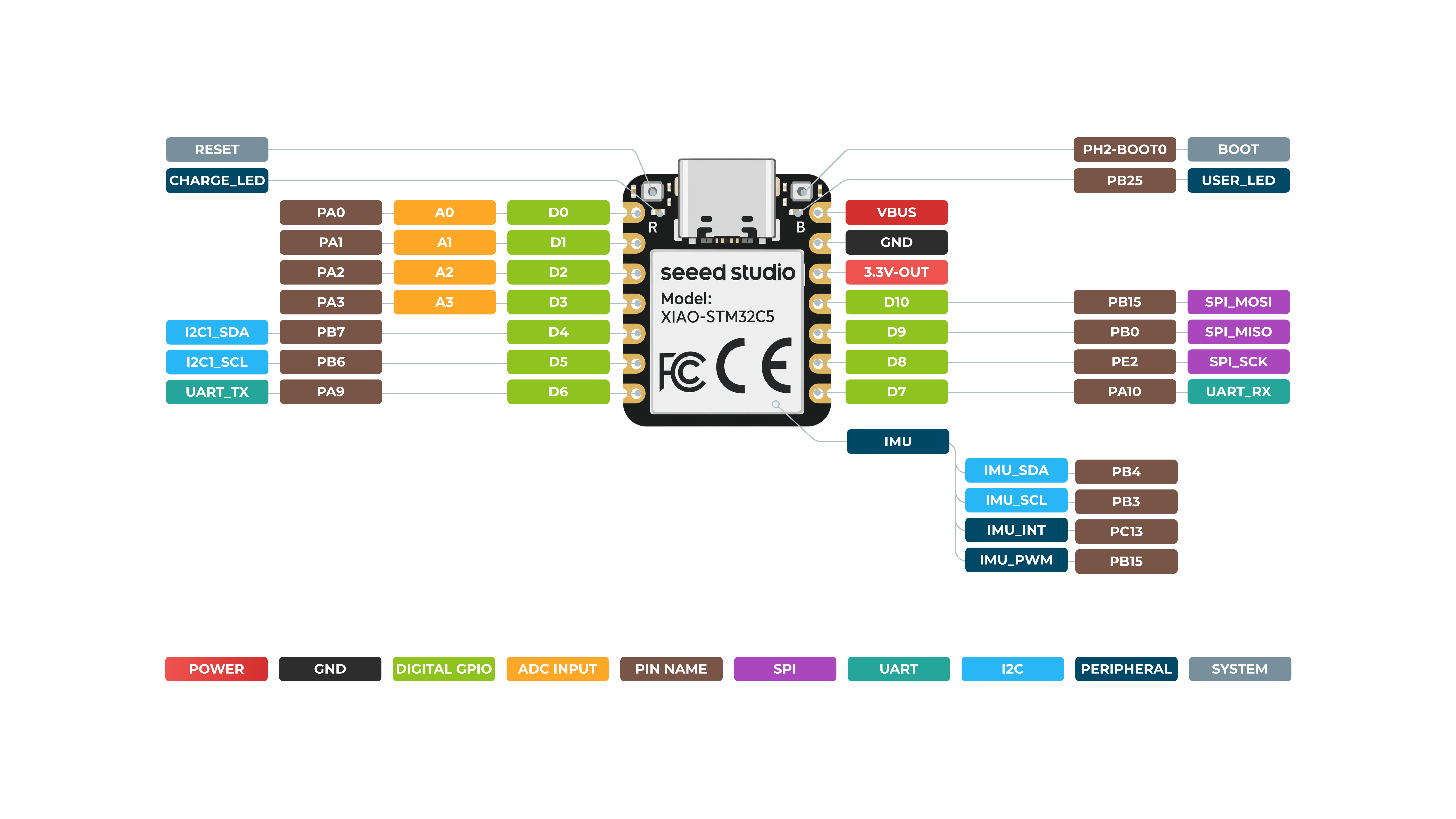
| XIAO Pin / Signal | Function | Chip Pin | Alternate Functions | Description |
|---|---|---|---|---|
| VBUS | Power | USB 5V | 5V power input/output | |
| GND | Ground | Power ground | ||
| 3V3 / 3.3V-OUT | Power | VOUT_3V3 | Regulated 3.3V output | |
| D0 | Analog | PA0 | A0, ADC | GPIO and analog input |
| D1 | Analog | PA1 | A1, ADC | GPIO and analog input |
| D2 | Analog | PA2 | A2, ADC | GPIO and analog input |
| D3 | Analog | PA3 | A3, ADC | GPIO and analog input |
| D4 | I2C | PB7 | I2C1_SDA | GPIO and I2C data |
| D5 | I2C | PB6 | I2C1_SCL | GPIO and I2C clock |
| D6 | UART | PA9 | UART_TX | GPIO and UART transmit |
| D7 | UART | PA10 | UART_RX | GPIO and UART receive |
| D8 | SPI | PE2 | SPI_SCK | GPIO and SPI clock |
| D9 | SPI | PB0 | SPI_MISO | GPIO and SPI data input |
| D10 | SPI | PB15 | SPI_MOSI | GPIO and SPI data output |
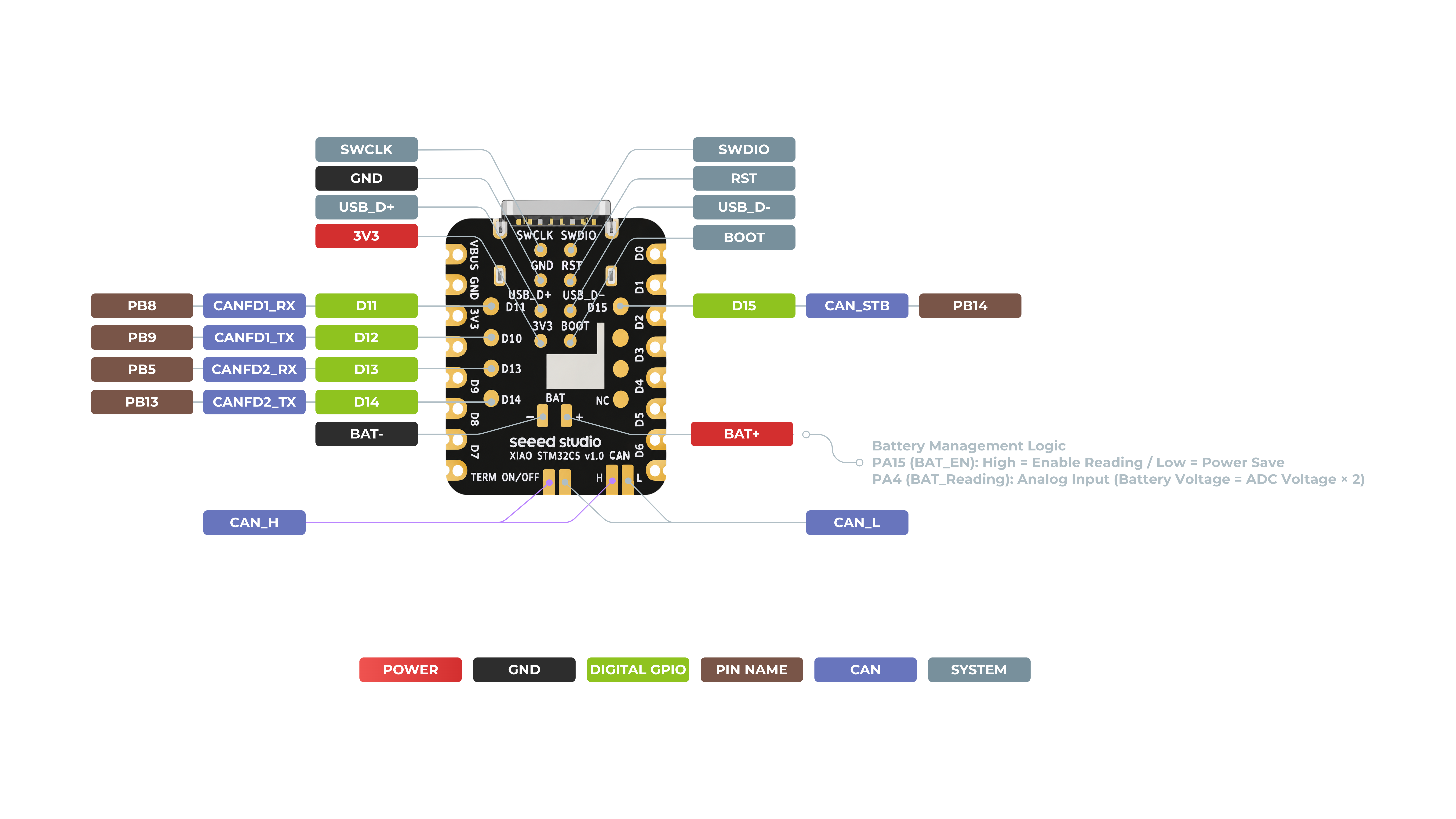
| D11 | CAN FD | PB8 | FDCAN1_RX | GPIO and FDCAN1 receive |
| D12 | CAN FD | PB9 | FDCAN1_TX | GPIO and FDCAN1 transmit |
| D13 | CAN FD | PB5 | FDCAN2_RX | GPIO and onboard CAN transceiver receive |
| D14 | CAN FD | PB13 | FDCAN2_TX | GPIO and onboard CAN transceiver transmit |
| D15 | CAN Control | PB14 | CAN_STB | Controls onboard CAN transceiver standby mode |
| CAN_H | CAN Bus | TCAN3403 CANH | CAN FD differential bus high | |
| CAN_L | CAN Bus | TCAN3403 CANL | CAN FD differential bus low | |
| CANFD2_TERM | CAN Termination | JP1, 120 ohm | Cut/open to disable the onboard 120-ohm termination resistor | |
| BAT+ | Battery Power | VBAT | Positive terminal for a 3.7V Li-ion/LiPo battery | |
| BAT- | Battery Ground | GND | Negative battery terminal | |
| BAT_EN | Battery Monitor | PA15 | Enables the battery-voltage measurement circuit | |
| BAT_READ | Analog | PA4 | ADC | Reads battery voltage; ADC input is approximately VBAT / 2 |
| SWCLK | Debug | PA14 | SWD Clock | Serial Wire Debug clock pad |
| SWDIO | Debug | PA13 | SWD Data | Serial Wire Debug data pad |
| RST | System | NRST | STM32C5_RESET | Hardware reset test pad |
| USB_D+ | USB | PA12 | USB_DP | USB 2.0 differential data positive |
| USB_D- | USB | PA11 | USB_DN | USB 2.0 differential data negative |
| BOOT | System | PH2-BOOT0 | STM32C5_BOOT | Boot-mode test pad and boot-button signal |
| CHARGE_LED | Indicator | Charger NCHG output | Red charging-status LED controlled by the charger IC | |
| USER_LED | GPIO Indicator | PB12 | GPIO25 / User_LED | Green user LED; connected active-low |
| IMU_SDA | Onboard IMU | PB4 | I2C2_SDA | I2C data for the onboard LSM6DS3TR-C IMU |
| IMU_SCL | Onboard IMU | PB3 | I2C2_SCL | I2C clock for the onboard LSM6DS3TR-C IMU |
| IMU_INT | Onboard IMU | PC13 | IMU_INT1 | Interrupt output from the onboard IMU |
| IMU_HEATER_PWM | IMU Heater | PA8 | PWM | PWM control for the IMU temperature-compensation heater |
Bootloader Usage
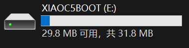
The XIAO STM32C5 is factory‑preloaded with a UF2‑capable bootloader primarily intended for firmware updates. Before flashing a .uf2 file, quickly double‑tap the on‑board Reset button. A mass‑storage drive named XIAOC5BOOT will mount on your PC. You can then copy the firmware file to this drive to complete flashing.
Getting Started With PlatformIO
This section demonstrates development and usage of the XIAO STM32C5 by lighting the on‑board user LED, using the PlatformIO development platform with the Zephyr RTOS framework.
Hardware Preparation
You need to prepare the following:
- 1 x Seeed Studio XIAO STM32C5
- 1 x Computer
- 1 x USB Type-C cable
| Seeed Studio XIAO STM32C5 |
|---|
|
Software Preparation
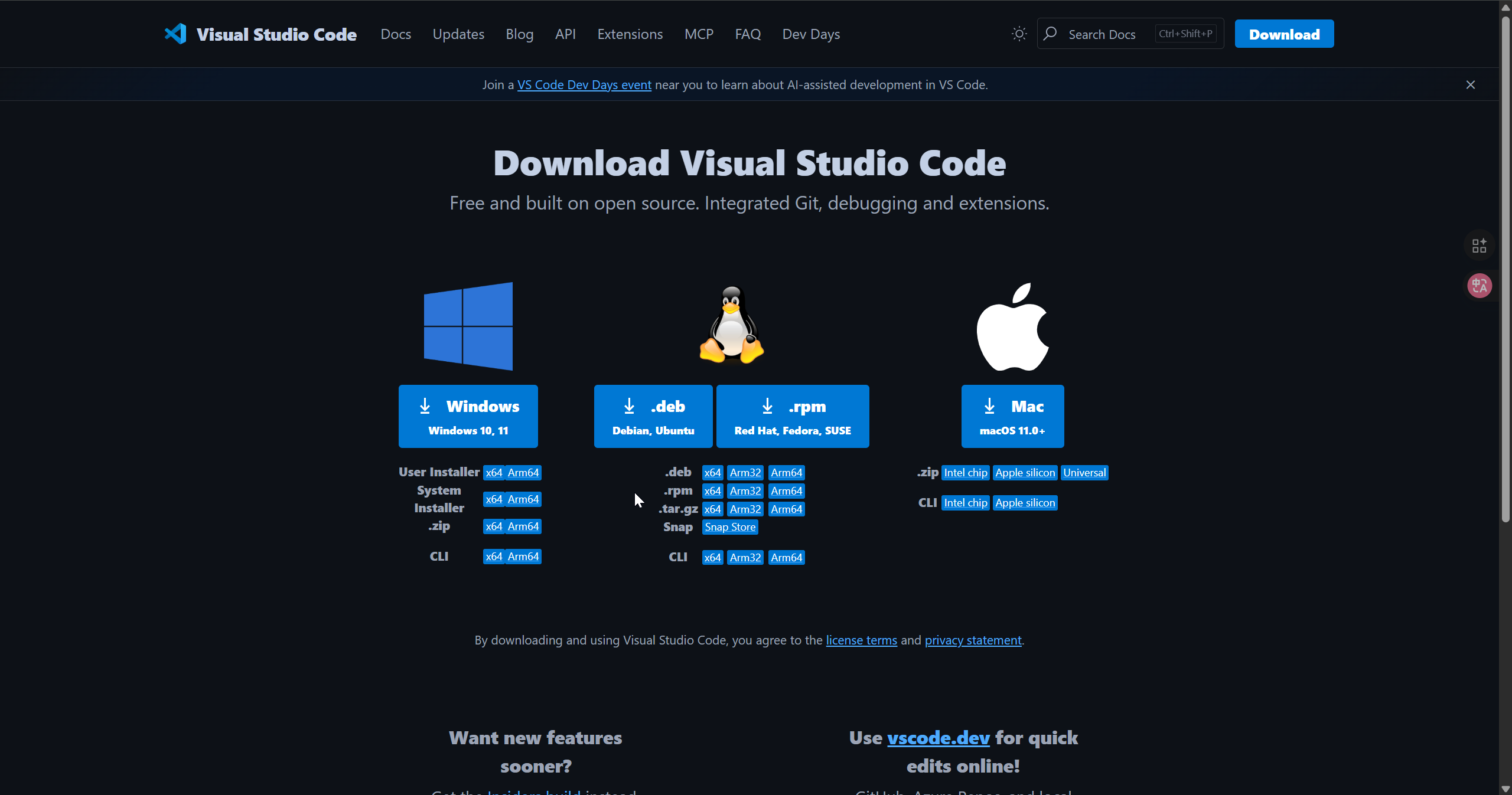
Step 1. Download VS Code
Download according to the system you are using VS Code
Step 2. Install the PlatformIO extension
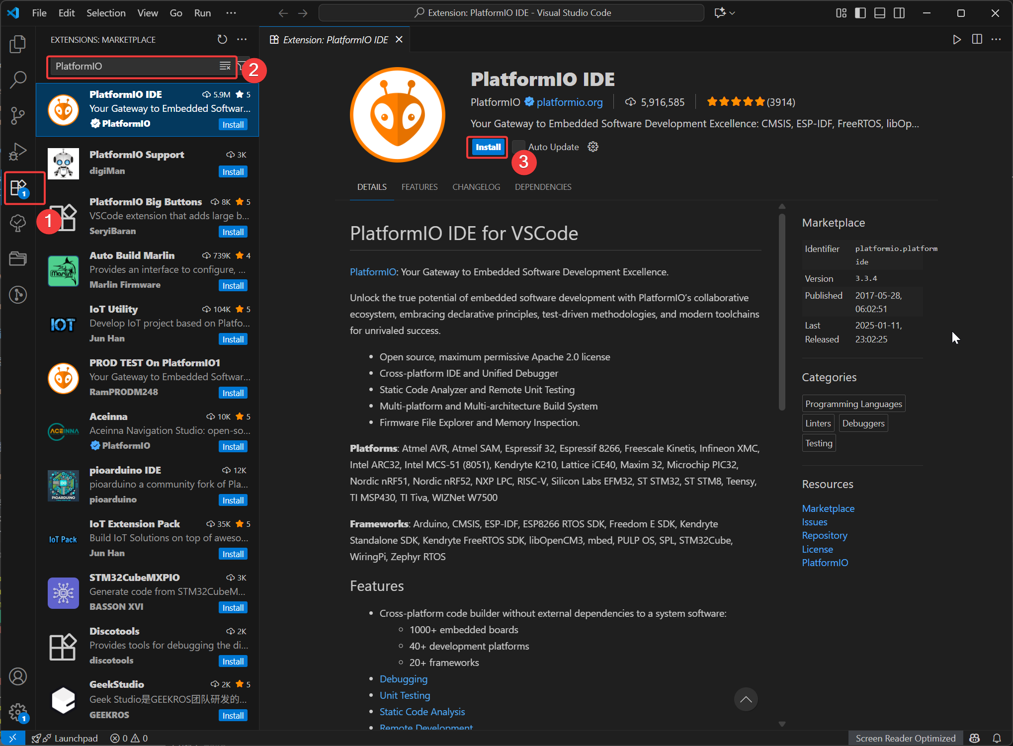
Open VSCode, click on Extensions, then search for PlatformIO and select to install. After the installation is complete, restart VSCode.
Step 3. Install the platform-seeedboards platform package
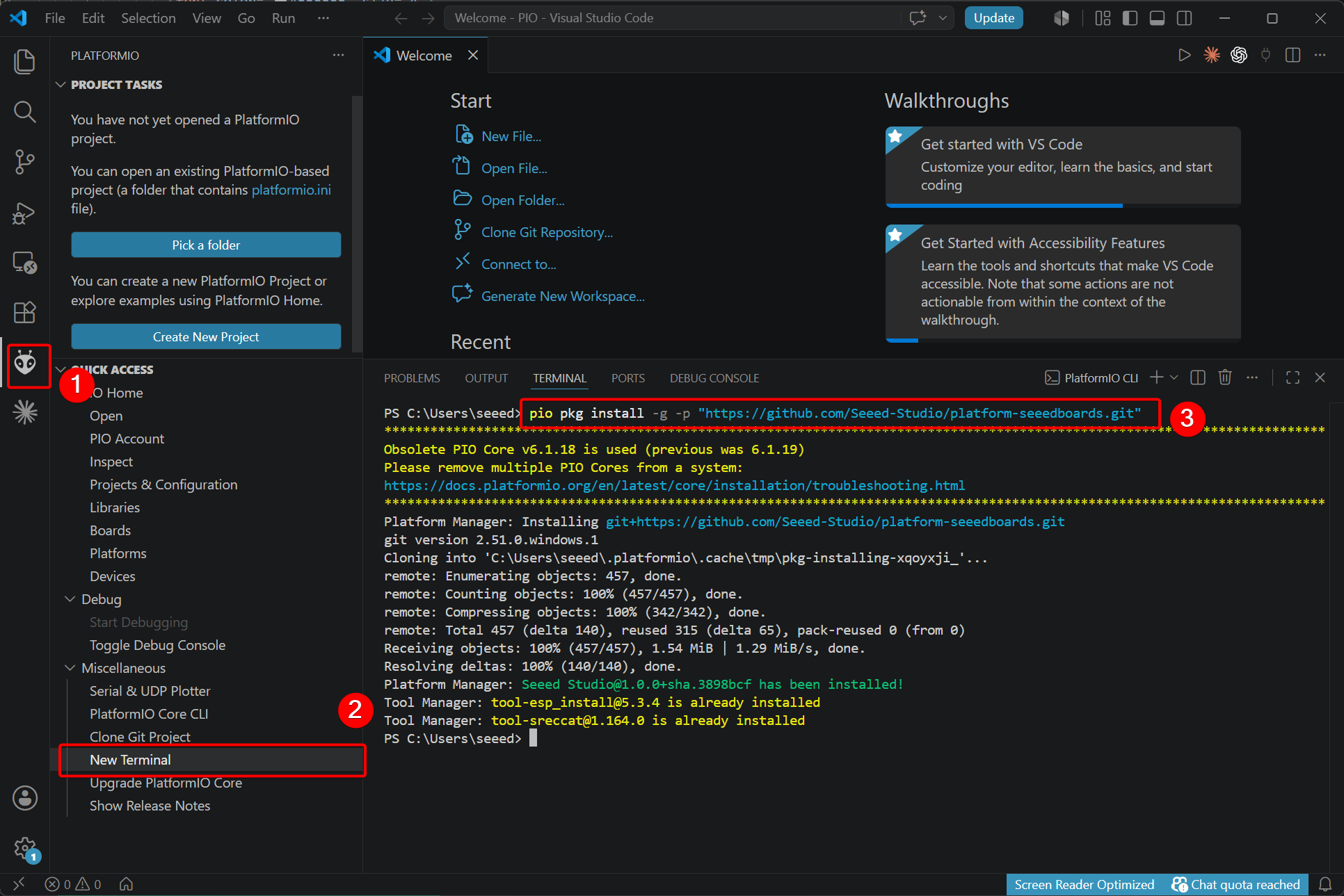
The Seeed Studio XIAO series boards use a custom PlatformIO platform, so you need to install the corresponding platform package manually.
- Run the following command for a fresh installation:
pio pkg install -g -p "https://github.com/Seeed-Studio/platform-seeedboards.git"
- If you have previously used Seeed Studio XIAO series boards in PlatformIO, run the command below to update:
# for Windows
pio pkg update -g -p "https://github.com/Seeed-Studio/platform-seeedboards.git"

# for macOS/Linux
pio pkg uninstall -g -p "SeeedStudio" && pio pkg install -g -p "SeeedStudio=https://github.com/Seeed-Studio/platform-seeedboards.git" --force
If you want to use an existing PlatformIO project, replace the content of platformio.ini as follows:
[env:seeed-xiao-stm32c5]
platform = https://github.com/Seeed-Studio/platform-seeedboards.git
framework = zephyr
board = seeed-xiao-stm32c5
Step 4. Create New Project
- On the PlatformIO plugin interface, select to create a new project.
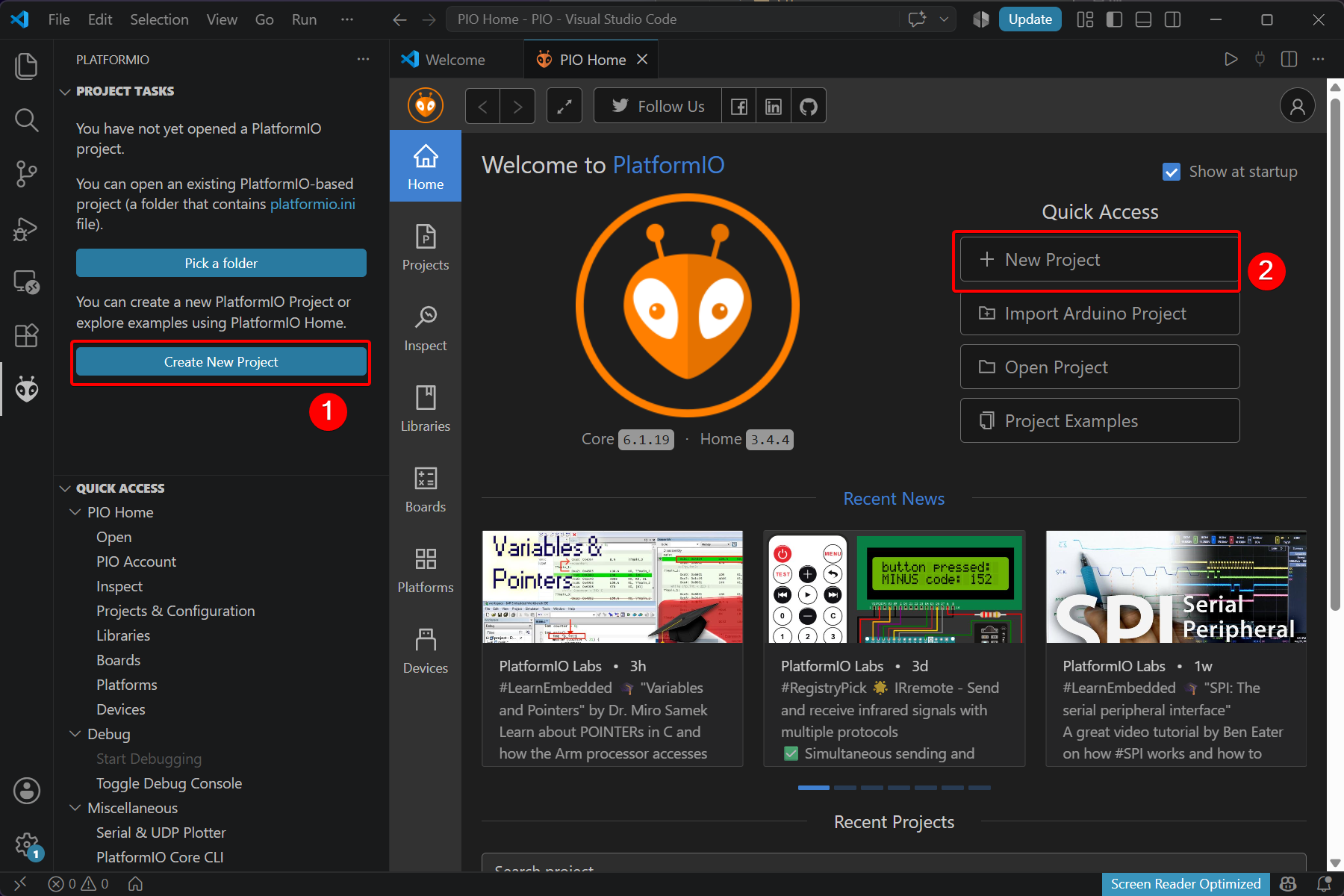
- Name your project, choose Seeed Studio XIAO STM32C5 as the target board, and configure the development framework and project storage path.
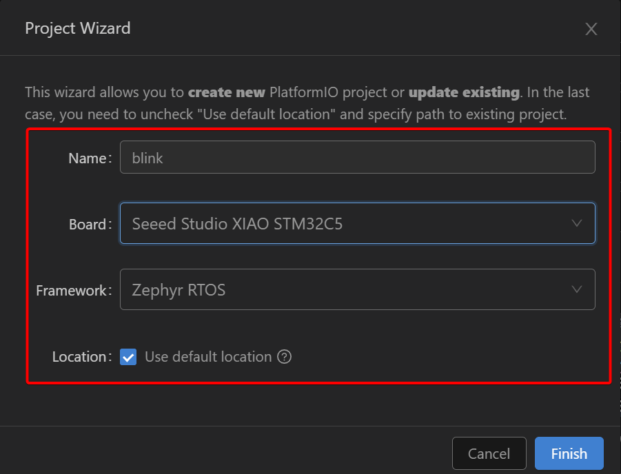
Project creation may take some time on the first launch, please wait patiently.
Build and Upload
Step 1. Write the LED Blink Program
The XIAO STM32C5 features one user LED mapped to GPIO PB12. The LED turns on at a low logic level; this example configures it to blink every 500 ms.
The project consists of three core files:
main.c: Main program that contains the application logic.app.overlay: Devicetree overlay file for hardware peripheral configuration.prj.conf: Project configuration file to enable required Zephyr modules.
Follow the steps below to turn on the LED:
- Open your newly‑created project and create the
app.overlaydevicetree file under thezephyrfolder.
- Create the
prj.confconfiguration file inside thezephyrfolder.
# GPIO for LED control
CONFIG_GPIO=y
- Copy the reference code shown below into
main.c.
/*
 * Copyright (c) 2026 Seeed Technology Co., Ltd.
 * SPDX-License-Identifier: Apache-2.0
 *
 * Blinky example for XIAO STM32C5 with TinyUF2 bootloader support.
 * Based on Zephyr samples/basic/blinky.
 *
 * The 1200-bps UF2 bootloader trigger is armed automatically by the
 * board support package — no code changes needed in this example.
 */

#include <zephyr/kernel.h>
#include <zephyr/drivers/gpio.h>

#define SLEEP_TIME_MS 500

#define LED0_NODE DT_ALIAS(led0)

static const struct gpio_dt_spec led = GPIO_DT_SPEC_GET(LED0_NODE, gpios);

int main(void)
{
	int ret;
	bool led_state = true;

	if (!gpio_is_ready_dt(&led)) {
		return 0;
	}

	ret = gpio_pin_configure_dt(&led, GPIO_OUTPUT_ACTIVE);
	if (ret < 0) {
		return 0;
	}

	while (1) {
		ret = gpio_pin_toggle_dt(&led);
		if (ret < 0) {
			return 0;
		}

		led_state = !led_state;
		printk("LED state: %s\n", led_state ? "ON" : "OFF");
		k_msleep(SLEEP_TIME_MS);
	}

	return 0;
}
Step 2. Build and Upload the Program
- On the bottom toolbar, trigger one‑click project building.
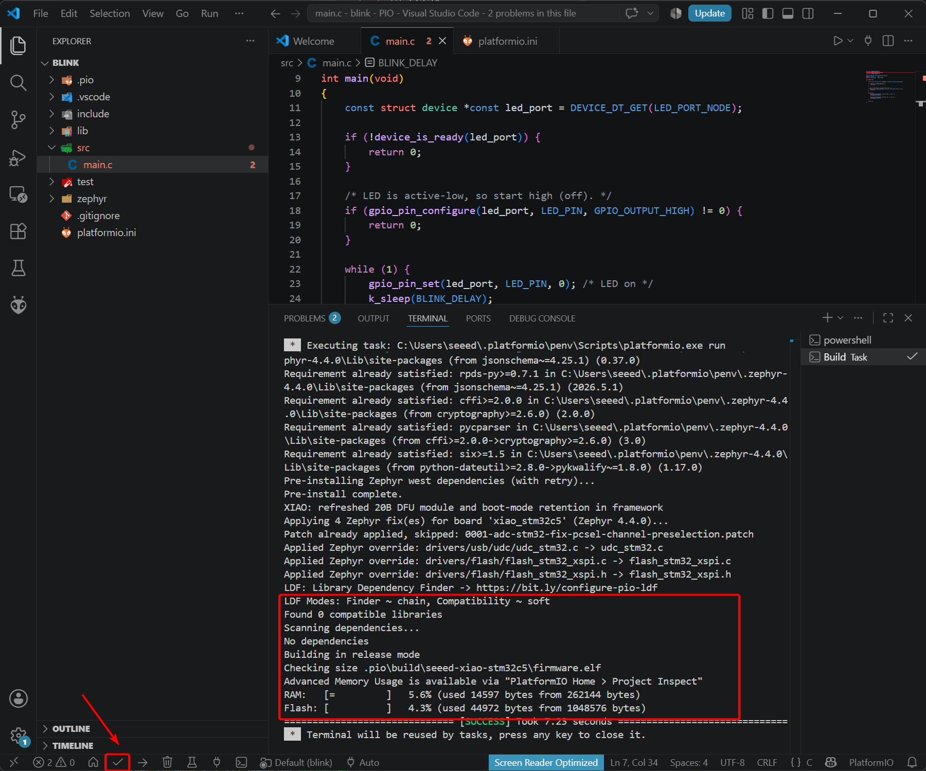
Alternatively, you may perform building via the command‑line interface.
pio run -e seeed-xiao-stm32c5
- Upload the firmware
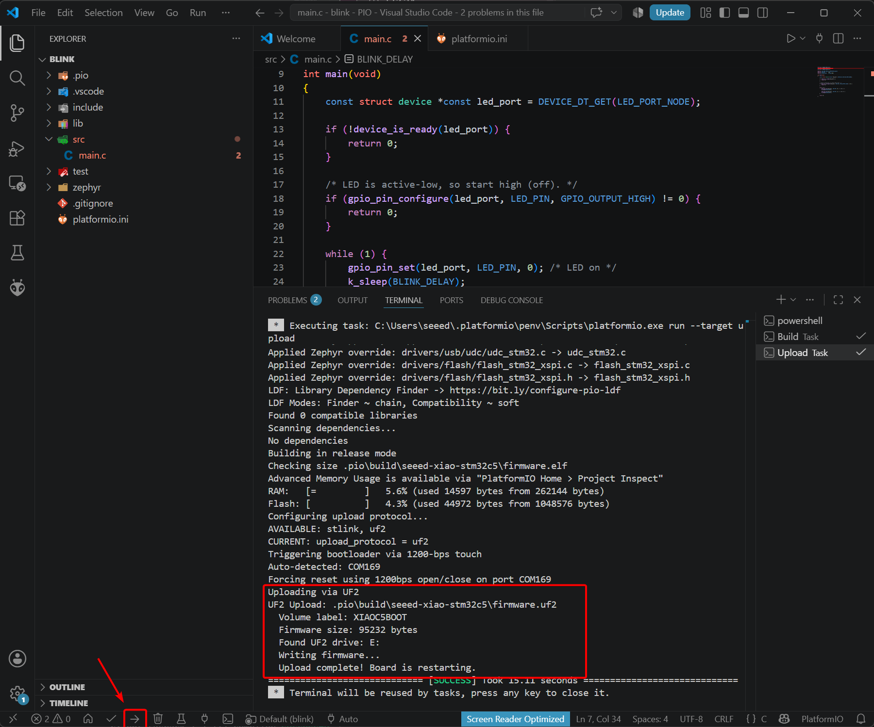
Similarly, firmware upload can also be completed through the command line.
pio run -e seeed-xiao-stm32c5 -t upload
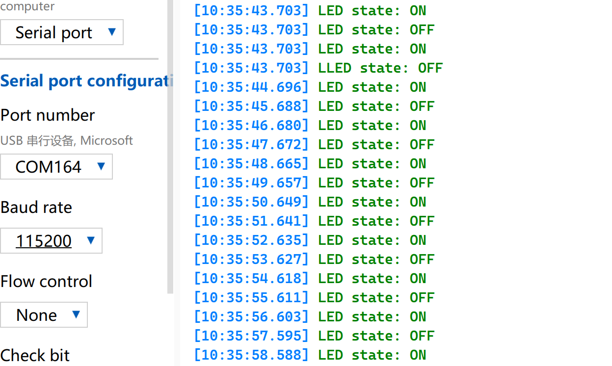
- Program Execution Result
The on‑board LED of XIAO STM32C5 blinks at a 500 ms interval.
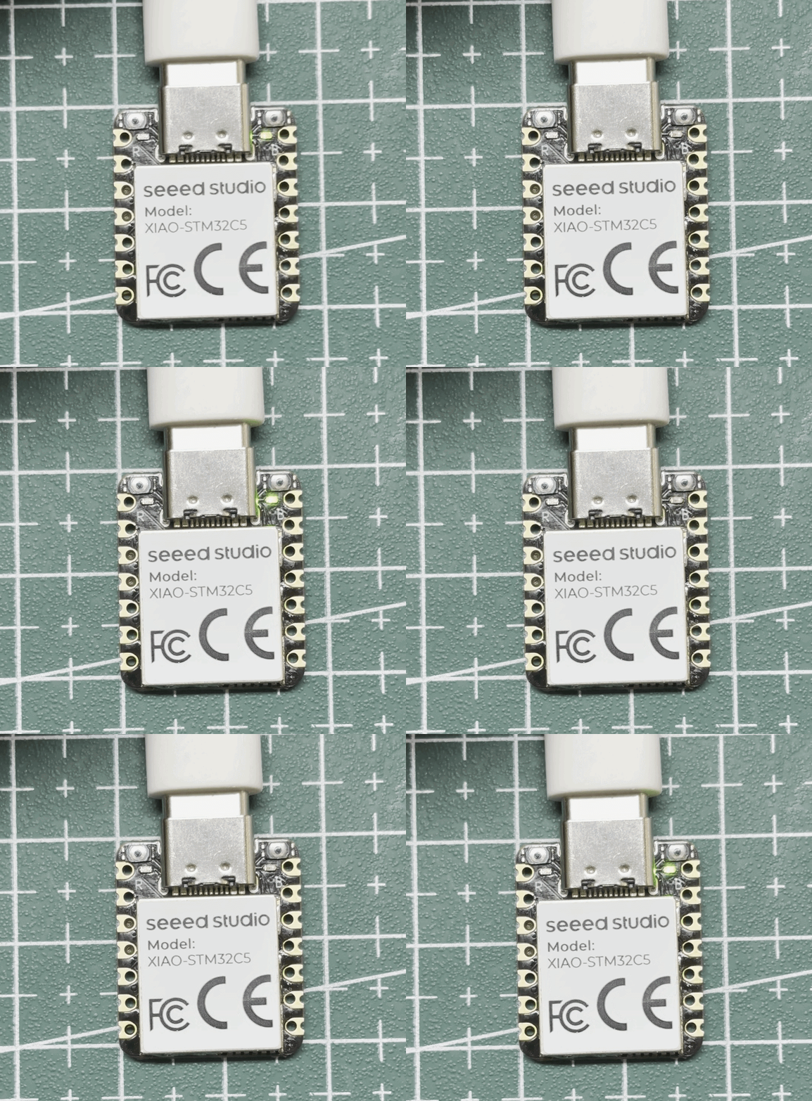
Meanwhile, the serial port outputs the on/off status of the LED.
Battery Usage
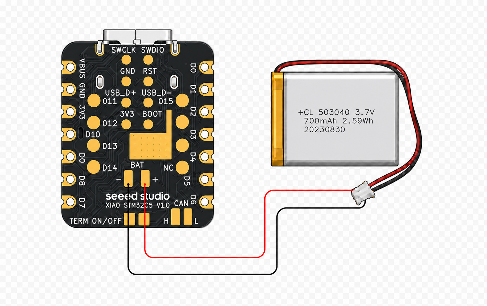
A BAT battery connector is reserved on the back side of the XIAO STM32C5 for power supply using a 3.7 V‑4.2 V lithium‑ion battery.
Read Battery Voltage
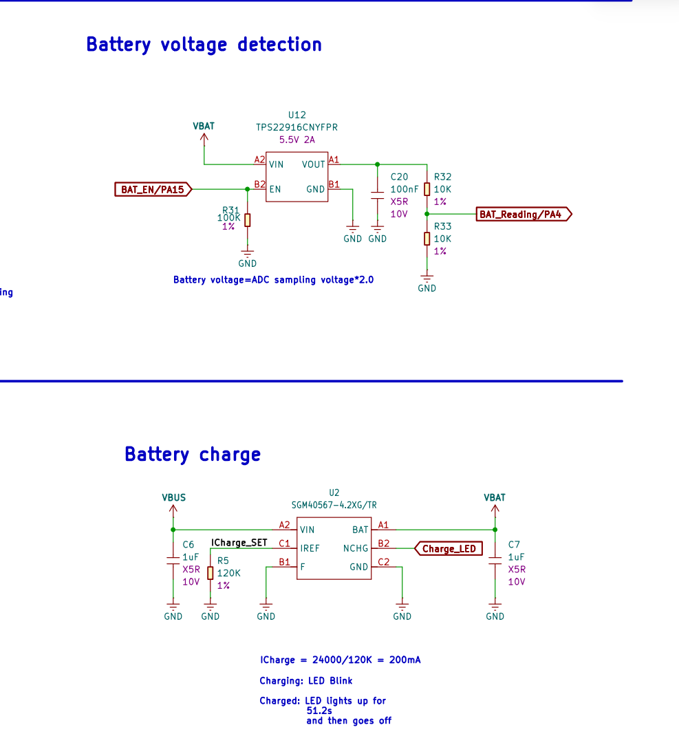
The XIAO STM32C5 incorporates battery voltage sensing circuitry and battery charging circuitry.
Within the sensing circuit, BAT_EN / PA15 enables the TPS22916CNYFPR chip, while BAT_Reading / PA4 reads the battery voltage. Two 10 kΩ voltage‑divider resistors are used, so the measured value equals one‑half of the actual lithium‑ion battery voltage.
The Charge_LED blinks during battery charging and turns off once charging is complete.
- Modify the corresponding application code.
app.overlay
prj.conf
main.c
/*
 * Copyright (c) 2026 Seeed Technology Co., Ltd.
 * SPDX-License-Identifier: Apache-2.0
 *
 * Read the XIAO STM32C5 battery voltage once per second.
 * printk() output uses USB CDC;
 * BAT_Reading/PA4 is added by app.overlay. BAT_EN/PA15 and USB CDC are
 * supplied by the board devicetree.
 */

#include <zephyr/device.h>
#include <zephyr/drivers/adc.h>
#include <zephyr/drivers/gpio.h>
#include <zephyr/kernel.h>
#include <zephyr/sys/printk.h>

#if !DT_NODE_EXISTS(DT_PATH(zephyr_user)) || \
	!DT_NODE_HAS_PROP(DT_PATH(zephyr_user), io_channels)
#error "No battery ADC io-channel specified"
#endif

#define BATTERY_ADC_NODE        DT_PATH(zephyr_user)
#define BAT_EN_NODE             DT_ALIAS(baten)
#define BATTERY_ENABLE_DELAY_MS 5
#define ADC_AVG_SAMPLES         16
#define SAMPLE_PERIOD_MS        1000

static const struct adc_dt_spec battery_adc =
	ADC_DT_SPEC_GET_BY_IDX(BATTERY_ADC_NODE, 0);
static const struct gpio_dt_spec bat_en =
	GPIO_DT_SPEC_GET(BAT_EN_NODE, gpios);

int main(void)
{
	uint16_t raw;
	struct adc_sequence sequence = {
		.buffer = &raw,
		.buffer_size = sizeof(raw),
	};
	int err;

	if (!device_is_ready(battery_adc.dev) || !gpio_is_ready_dt(&bat_en)) {
		printk("Battery ADC hardware is not ready\n");
		return 0;
	}

	err = gpio_pin_configure_dt(&bat_en, GPIO_OUTPUT_ACTIVE);
	if (err) {
		printk("BAT_EN configure failed: %d\n", err);
		return 0;
	}

	k_msleep(BATTERY_ENABLE_DELAY_MS);

	err = adc_channel_setup_dt(&battery_adc);
	if (err) {
		printk("Battery ADC channel setup failed: %d\n", err);
		return 0;
	}

	err = adc_sequence_init_dt(&battery_adc, &sequence);
	if (err) {
		printk("Battery ADC sequence init failed: %d\n", err);
		return 0;
	}

	printk("Battery voltage monitor (USB CDC)\n");

	while (1) {
		uint32_t raw_sum = 0;
		uint16_t raw_avg;
		int32_t adc_mv;

		/* Discard the first conversion after the one-second idle period. */
		err = adc_read(battery_adc.dev, &sequence);
		for (int i = 0; !err && i < ADC_AVG_SAMPLES; i++) {
			err = adc_read(battery_adc.dev, &sequence);
			raw_sum += raw;
		}

		if (!err) {
			raw_avg = raw_sum / ADC_AVG_SAMPLES;
			adc_mv = raw_avg;
			err = adc_raw_to_millivolts_dt(&battery_adc, &adc_mv);
			if (err) {
				printk("Battery voltage conversion failed: %d\n", err);
			} else {
				/* The 1:1 divider halves the battery voltage. */
				printk("Battery: %d mV\n", adc_mv * 2);
			}
		} else {
			printk("Battery ADC read failed: %d\n", err);
		}

		k_msleep(SAMPLE_PERIOD_MS);
	}

	return 0;
}
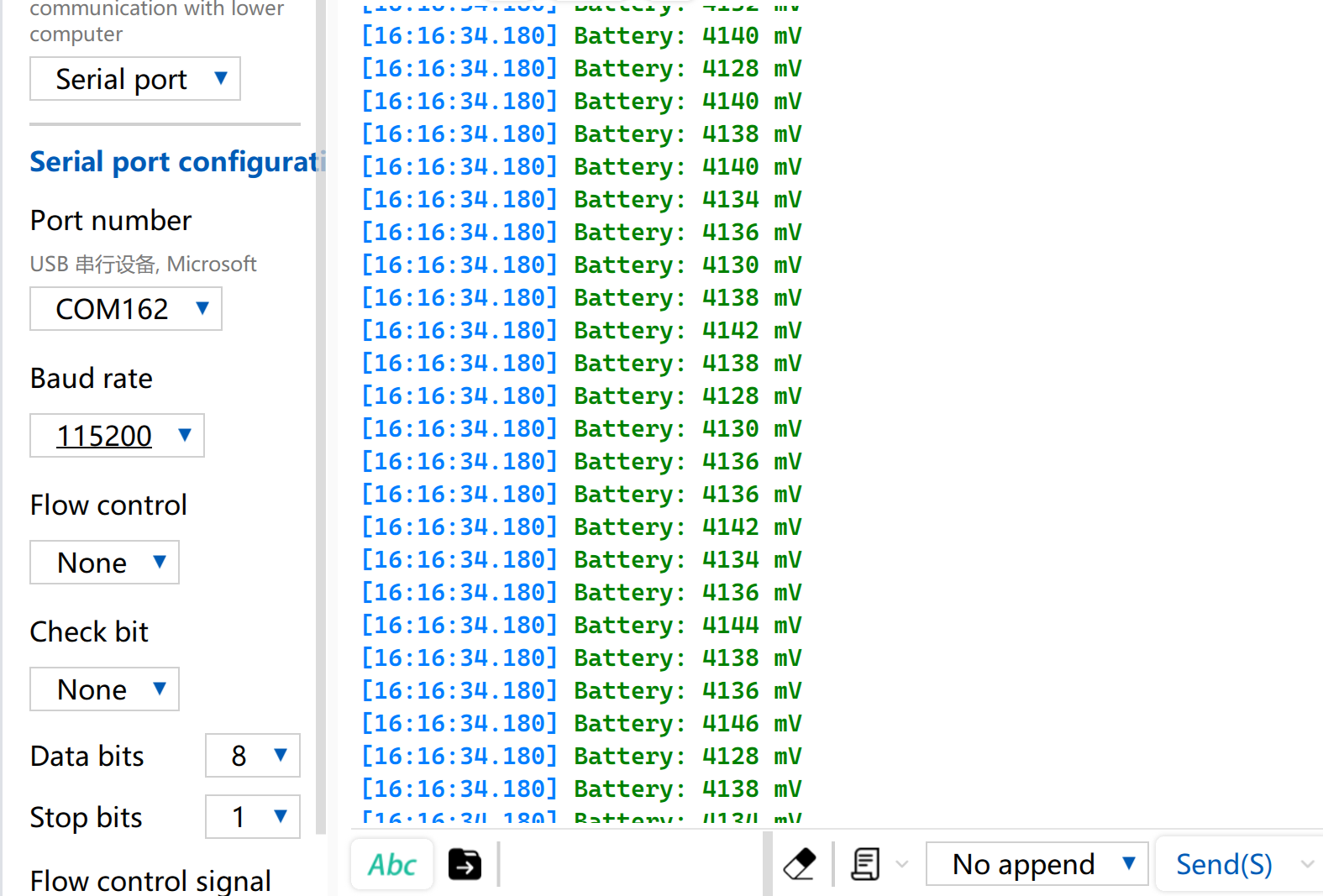
- Voltage Reading Result
IMU
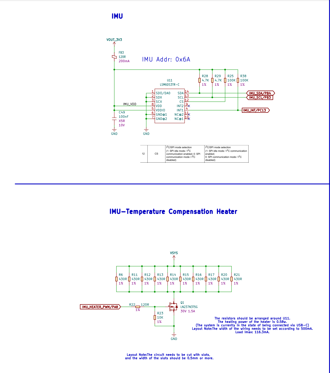
The XIAO STM32C5 carries an on‑board LSM6DS3TR‑C 6‑axis inertial sensor, which integrates a 3‑axis accelerometer and a 3‑axis gyroscope. It can be applied to attitude detection, motion recognition, vibration monitoring and other use‑cases.
To mitigate the impact of ambient temperature variation on sensor bias and measurement stability, the board implements an active temperature‑compensation heating circuit. Heating resistors placed around the IMU provide uniform heating for the sensor, and heating power can be adjusted via PWM signals. Combined with internal temperature readings from the IMU, software control keeps the sensor operating at a relatively stable temperature. This reduces measurement drift caused by temperature drift and improves data consistency during long‑term operation and under variable‑temperature conditions.
- Reference Usage: XIAO STM32C5 IMU Usage
CAN FD
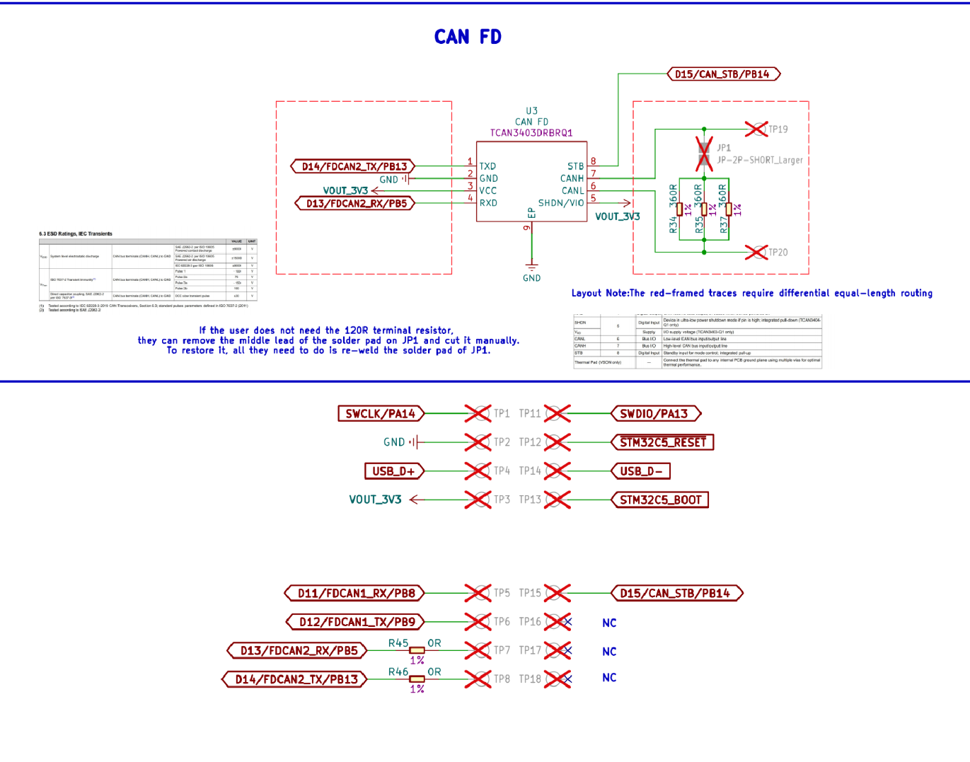
The XIAO STM32C5 has two CAN FD controllers. FDCAN1 exposes logic-level TX and RX pins and requires an external CAN transceiver for connection to a CAN bus. FDCAN2 is connected to the onboard TCAN3403-Q1 transceiver and connects to the bus through the CAN_H and CAN_L pads. The board can also exchange Classical CAN frames. However, Classical CAN-only nodes cannot decode CAN FD frames, so confirm that the active nodes on the bus support CAN FD before transmitting FD traffic. CAN FD supports payloads of up to 64 bytes and, when bit-rate switching is enabled, a higher bit rate during the data phase.
The board has a disconnectable onboard 120 Ω termination resistor, enabled by default. Keep it enabled when the XIAO is at a physical end of the CAN bus and that end has no other terminator. Disable it when the XIAO is an intermediate node or another terminator is already installed at the same end. Ensure that the opposite end of the bus is also properly terminated. The transceiver supports standby mode to reduce power consumption when CAN communication is not needed.
- Reference Usage: XIAO STM32C5 CANFD Usage
Resources
Hardware Design
- 📄[Datasheet] STM32C5A3CG
- 📄[Datasheet] LSM6DS3TR-C
- 📄[Datasheet] TCAN3403D4BQ1
- 📄[Schematic] XIAO STM32C5 Schematic
- 🗃️[PCB Design Files]
- 🗃️[PCB Design Libraries]
- 📄[Pinout Diagram] XIAO STM32C5 Pinout Sheet
Tech Support & Product Discussion
Thank you for choosing our products! We are here to provide you with different support to ensure that your experience with our products is as smooth as possible. We offer several communication channels to cater to different preferences and needs.