Pin Multiplexing with XIAO STM32C5
Overview
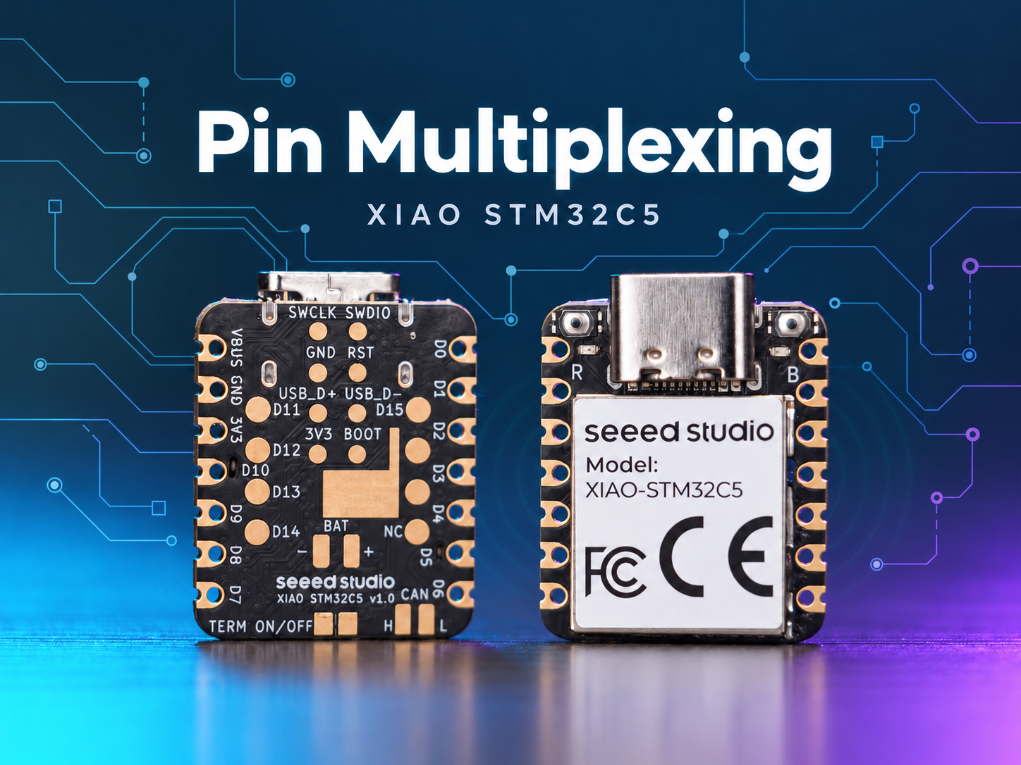
The XIAO STM32C5 features abundant pin resources and natively supports development with various standard peripheral interfaces including Digital, Analog, SPI and IIC. This article demonstrates relevant implementations with practical application cases.
This tutorial is developed based on the PlatformIO build system and Zephyr RTOS. If you are not familiar with creating a project for the XIAO STM32C5 under PlatformIO, you can jump to Getting Started With Seeed Studio XIAO STM32C5
Digital
Digital pins mainly realize on-off control of external sensors and actuators by outputting high and low logic levels. Combined with the Grove Base for XIAO expansion board and standard Grove peripheral modules, this section elaborates on the underlying driver logic and practical invocation methods of digital pins on XIAO STM32C5.
Hardware Preparation
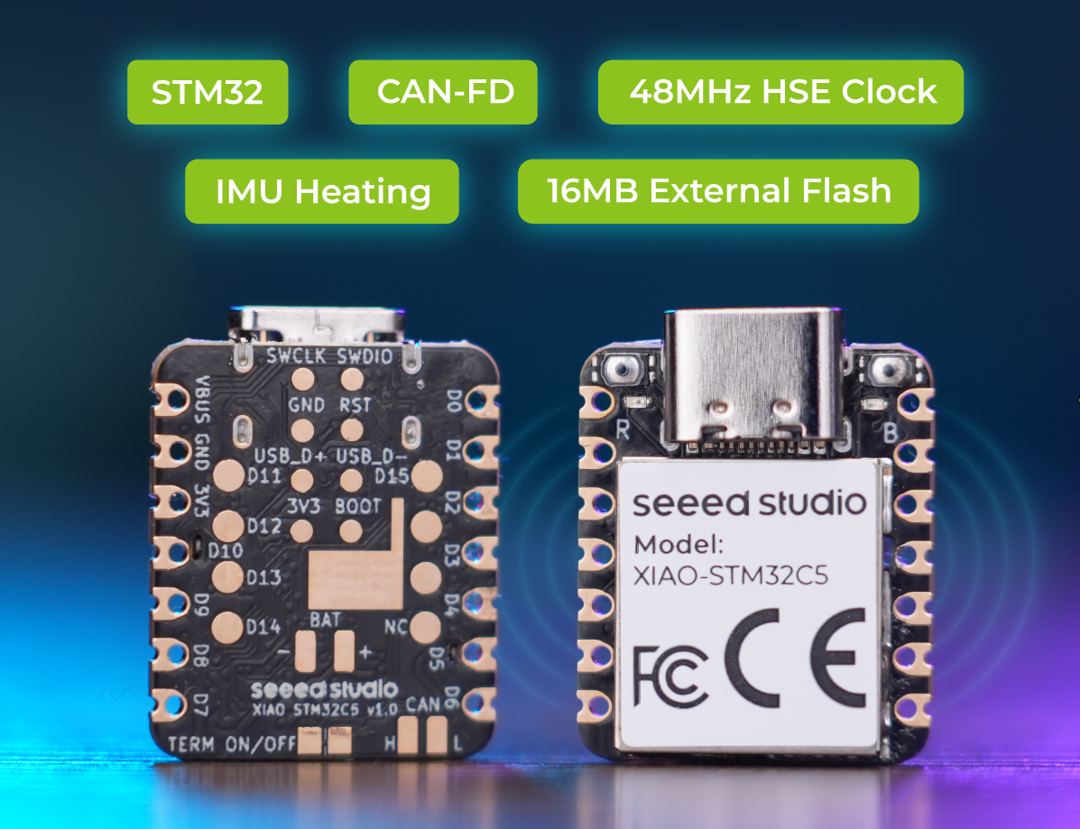
| Seeed Studio XIAO STM32C5 | Seeed Studio Grove Base for XIAO | Grove - LED Pack |
|---|---|---|
 |  |  |
Software Preparation
According to the pinout of the XIAO STM32C5, D1 can be selected as the control pin for the Grove - LED Pack
- For the pinout of the XIAO STM32C5, click XIAO STM32C5 Pin List to view details.
Write the program for main.c
/*
 * Copyright (c) 2026 Seeed Technology Co., Ltd.
 * SPDX-License-Identifier: Apache-2.0
 *
 * Blinky example for XIAO STM32C5 with TinyUF2 bootloader support.
 * Based on Zephyr samples/basic/blinky.
 *
 * The 1200-bps UF2 bootloader trigger is armed automatically by the
 * board support package — no code changes needed in this example.
 */

#include <zephyr/kernel.h>
#include <zephyr/drivers/gpio.h>

#define SLEEP_TIME_MS 1000

#define D1_PIN 1

static const struct device *const d1_gpio = DEVICE_DT_GET(DT_NODELABEL(gpioa));

int main(void)
{
	int ret;
	bool led_state = true;

	if (!device_is_ready(d1_gpio)) {
		return 0;
	}

	ret = gpio_pin_configure(d1_gpio, D1_PIN, GPIO_OUTPUT_ACTIVE);
	if (ret < 0) {
		return 0;
	}

	while (1) {
		ret = gpio_pin_toggle(d1_gpio, D1_PIN);
		if (ret < 0) {
			return 0;
		}

		led_state = !led_state;
		printk("LED state: %s\n", led_state ? "ON" : "OFF");
		k_msleep(SLEEP_TIME_MS);
	}

	return 0;
}
Result
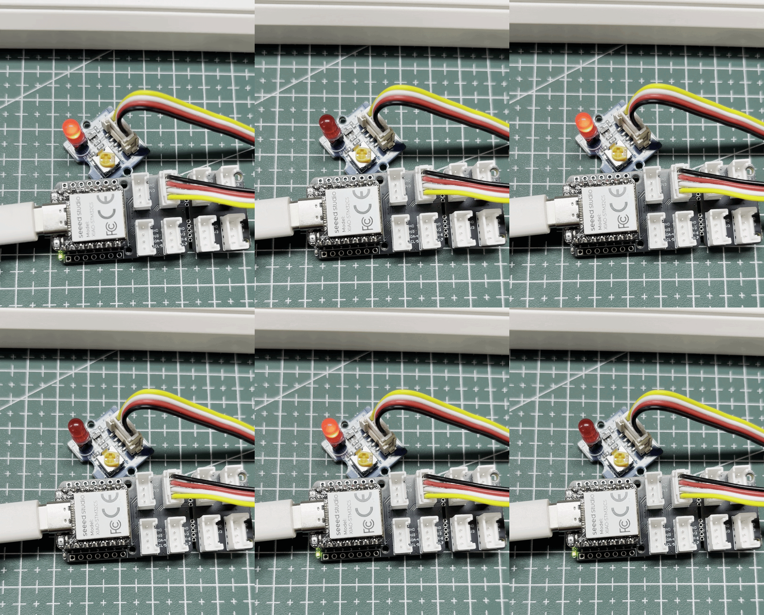
After flashing the firmware, the red LED blinks.
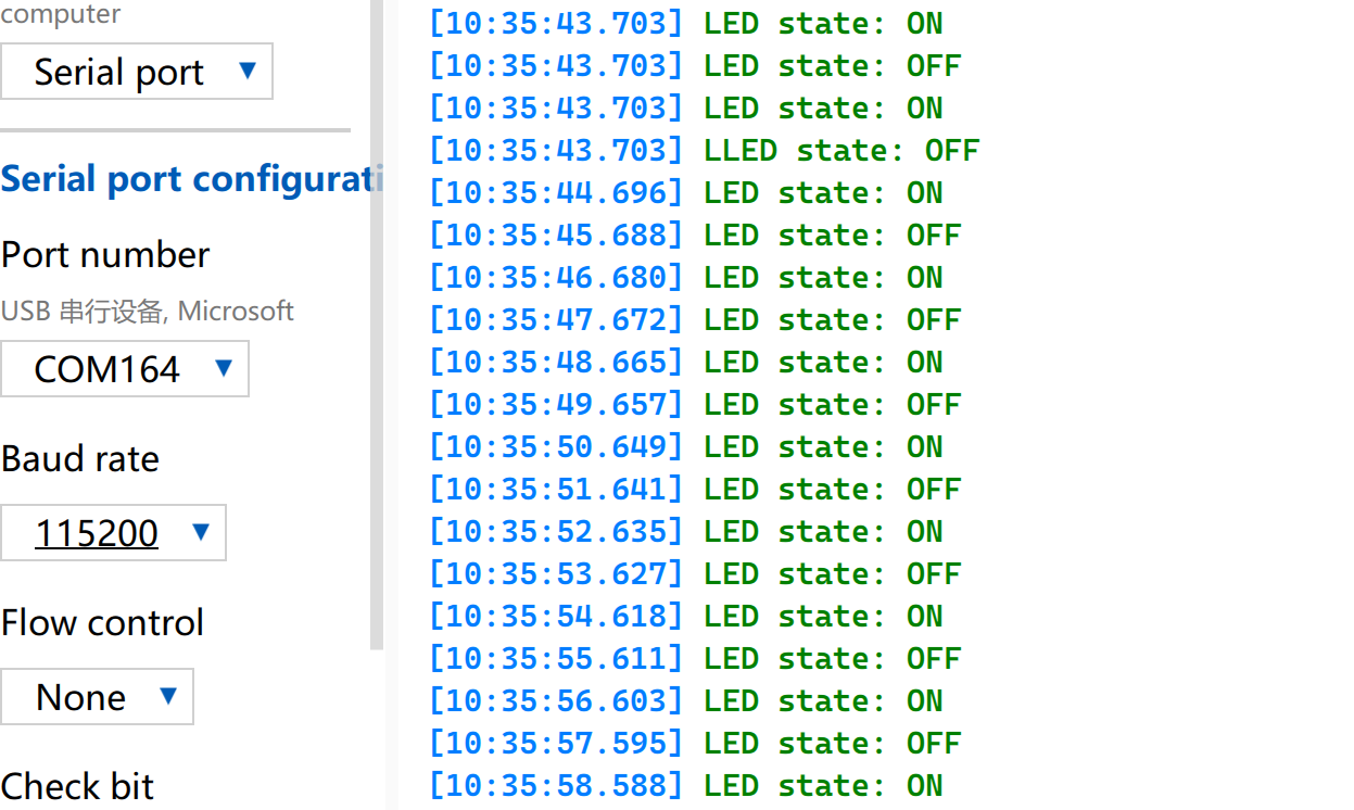
Open the Serial Monitor and set the baud rate to 115200.
PWM
PWM is a timing waveform output function implemented based on digital output GPIOs. It rapidly switches pin levels at a fixed frequency and dynamically adjusts the duty cycle of high level within a single cycle, so as to output equivalent analog signals to peripherals. In practical engineering applications, PWM is widely used for precise angle control of servo motors and smooth brightness adjustment of LEDs.
Drive a Servo Motor
Hardware Preparation
| Seeed Studio XIAO STM32C5 | Seeed Studio Grove Base for XIAO | Grove - Servo |
|---|---|---|
| |  |
Software Preparation
According to the pinout of the XIAO STM32C5, D0 can be selected as the control pin for the Grove-Servo.
- For the pinout of the XIAO STM32C5, click XIAO STM32C5 Pin List to view details.
- Modify the
app.overlayfile. On the XIAO STM32C5, D0 corresponds to the PA0 pin. By configuring PA0 as the AF1 alternate function in the DeviceTree, TIM2_CH1 can be used to output a PWM signal.
app.overlay
#include <zephyr/dt-bindings/pwm/pwm.h>

&{/pwmleds} {
	servo: servo {
		pwms = <&pwm2 1 PWM_MSEC(20) PWM_POLARITY_NORMAL>;
	};
};

&timers2 {
	st,prescaler = <143>;
	status = "okay";

	pwm2: pwm {
		pinctrl-0 = <&tim2_ch1_pa0>;
		pinctrl-names = "default";
		status = "okay";
	};
};
- Modify the
prj.conffile to enable relevant PWM configurations.
CONFIG_PWM=y
- Write the main.c program to implement PWM servo control function and configure parameters such as PWM period.
main.c
#include <zephyr/kernel.h>
#include <zephyr/device.h>
#include <zephyr/drivers/pwm.h>
#include <zephyr/sys/printk.h>

#define SERVO_PERIOD_NS PWM_MSEC(20)
#define SERVO_MIN_NS PWM_USEC(500)
#define SERVO_MAX_NS PWM_USEC(2500)
#define SERVO_CHANNEL 1
#define STEP_FWD_MS 10
#define STEP_RET_MS 30

static const struct device *pwm_dev = DEVICE_DT_GET(DT_NODELABEL(pwm2));

static int set_angle(int degrees)
{
	uint32_t pulse = SERVO_MIN_NS +
		(uint32_t)((uint64_t)degrees *
		(SERVO_MAX_NS - SERVO_MIN_NS) / 180U);

	return pwm_set(pwm_dev, SERVO_CHANNEL, SERVO_PERIOD_NS, pulse,
		PWM_POLARITY_NORMAL);
}

int main(void)
{
	printk("=== boot ===\n");

	if (!device_is_ready(pwm_dev)) {
		printk("Error: PWM device not ready\n");
		return -1;
	}

	printk("Servo control started on D0\n");

	while (1) {
		for (int angle = 0; angle <= 180; angle++) {
			if (set_angle(angle)) {
				printk("PWM error at %d deg\n", angle);
			} else {
				printk("Angle: %d deg\n", angle);
			}
			k_msleep(STEP_FWD_MS);
		}

		for (int angle = 180; angle >= 0; angle--) {
			if (set_angle(angle)) {
				printk("PWM error at %d deg\n", angle);
			} else {
				printk("Angle: %d deg\n", angle);
			}
			k_msleep(STEP_RET_MS);
		}
	}

	return 0;
}
Result
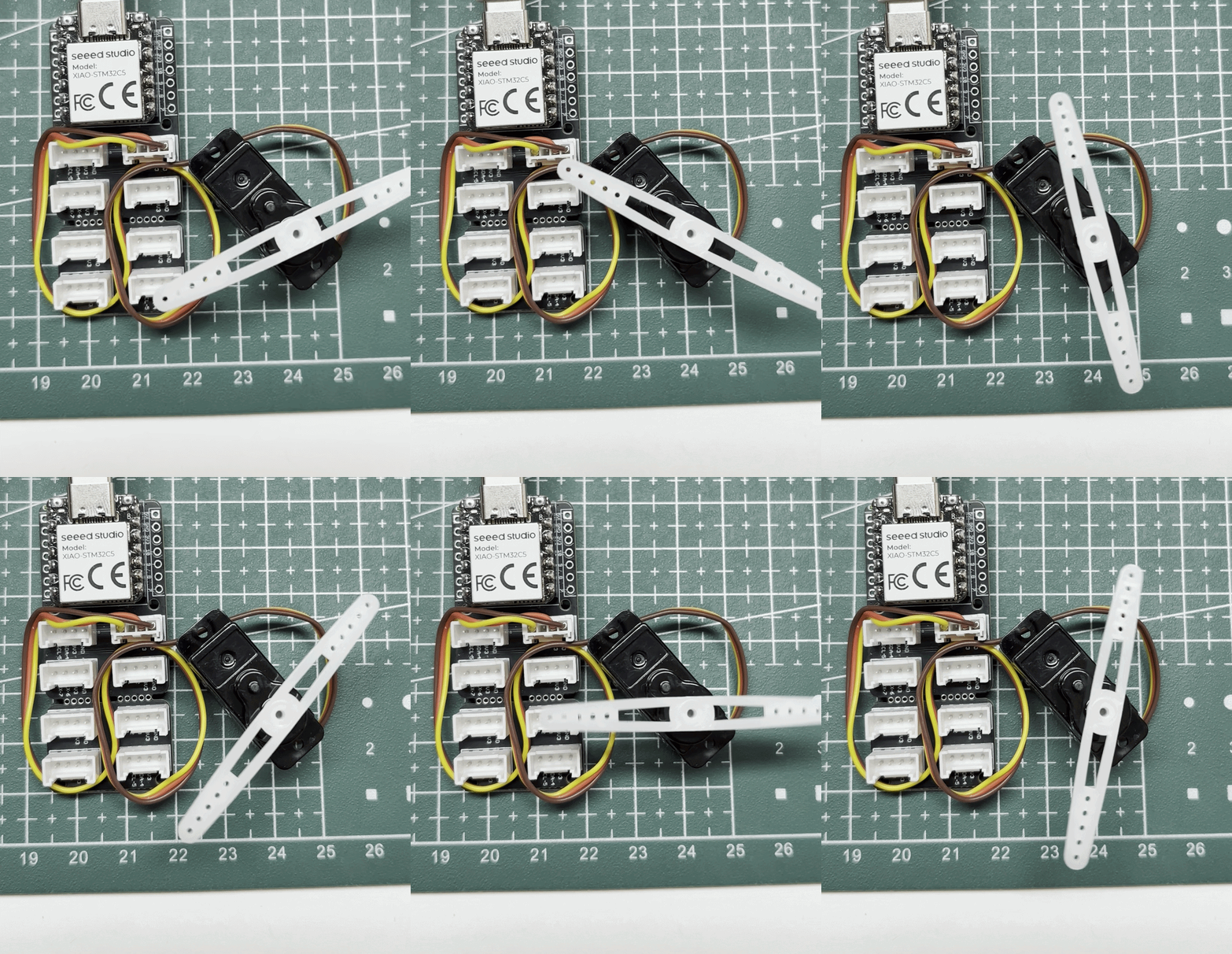
The commanded angle advances by 1° every 10 ms from 0° to 180°, then decreases by 1° every 30 ms. Actual movement speed depends on the servo.
Control a Buzzer
The Seeed Studio Expansion Board Base for XIAO is equipped with an onboard passive electromagnetic buzzer that can be driven by PWM signals. By adjusting the frequency, duty cycle, and output timing of the PWM, the pitch, volume, and duration of the buzzer's sound can be controlled, thereby enabling functions such as key prompt sounds, status alerts, and alarms.
Hardware Preparation
| Seeed Studio XIAO STM32C5 | Seeed Studio Expansion Board Base for XIAO |
|---|---|
|  |
Software Preparation
- For the pinout of the XIAO STM32C5, click XIAO STM32C5 Pin List to view details.
- Modify the
app.overlayfile. On the XIAO STM32C5, A3/D3 corresponds to the PA3 pin, which is connected to the onboard LET5020CS-03L passive electromagnetic buzzer through a 2N7002PW MOSFET on the Seeed Studio Expansion Board Base for XIAO. By configuring PA3 as the AF1 alternate function in the DeviceTree, TIM2_CH4 can output a 4 kHz PWM signal with a 250 μs period and 50% duty cycle to drive the buzzer.
app.overlay
#include <zephyr/dt-bindings/gpio/gpio.h>
#include <zephyr/dt-bindings/input/input-event-codes.h>
#include <zephyr/dt-bindings/pwm/pwm.h>

/ {
	buttons {
		compatible = "gpio-keys";

		expansion_button: button {
			gpios = <&xiao_d 1 (GPIO_PULL_UP | GPIO_ACTIVE_LOW)>;
			zephyr,code = <INPUT_KEY_0>;
		};
	};

	pwmleds {
		compatible = "pwm-leds";

		expansion_buzzer: buzzer {
			/* LET5020CS-03L: 4 kHz resonant frequency. */
			pwms = <&pwm2 4 PWM_USEC(250) PWM_POLARITY_NORMAL>;
		};
	};

	aliases {
		sw1 = &expansion_button;
		buzzer = &expansion_buzzer;
	};
};

&timers2 {
	st,prescaler = <143>;
	status = "okay";

	pwm2: pwm {
		pinctrl-0 = <&tim2_ch4_pa3>;
		pinctrl-names = "default";
		status = "okay";
	};
};
- Modify the
prj.conffile to enable relevant PWM configurations.
CONFIG_GPIO=y
CONFIG_PWM=y
- Modify the main.c program.
main.c
/*
 * Copyright (c) 2026 Seeed Technology Co., Ltd.
 * SPDX-License-Identifier: Apache-2.0
 *
 * Expansion Board Base for XIAO buzzer demo:
 * press the onboard button (D1) to sound the onboard buzzer (A3/D3).
 */

#include <zephyr/kernel.h>
#include <zephyr/drivers/gpio.h>
#include <zephyr/drivers/pwm.h>
#include <zephyr/sys/printk.h>

static const struct gpio_dt_spec button =
	GPIO_DT_SPEC_GET(DT_ALIAS(sw1), gpios);
static const struct pwm_dt_spec buzzer =
	PWM_DT_SPEC_GET(DT_ALIAS(buzzer));

int main(void)
{
	bool buzzer_on = false;
	int ret;

	if (!gpio_is_ready_dt(&button) || !pwm_is_ready_dt(&buzzer)) {
		printk("Button or buzzer device not ready\n");
		return -1;
	}

	ret = gpio_pin_configure_dt(&button, GPIO_INPUT);
	if (ret < 0) {
		printk("Button configuration failed: %d\n", ret);
		return ret;
	}

	ret = pwm_set_dt(&buzzer, buzzer.period, 0);
	if (ret < 0) {
		printk("Buzzer configuration failed: %d\n", ret);
		return ret;
	}

	printk("Press the D1 button to sound the A3 buzzer\n");

	while (1) {
		int pressed = gpio_pin_get_dt(&button);

		if (pressed < 0) {
			printk("Button read failed: %d\n", pressed);
			return pressed;
		}

		if ((pressed != 0) != buzzer_on) {
			ret = pwm_set_dt(&buzzer, buzzer.period,
					 pressed ? buzzer.period / 2U : 0U);
			if (ret < 0) {
				printk("Buzzer control failed: %d\n", ret);
				return ret;
			}

			buzzer_on = pressed != 0;
			printk("Buzzer: %s\n", buzzer_on ? "ON" : "OFF");
		}

		k_msleep(20);
	}
}
Result
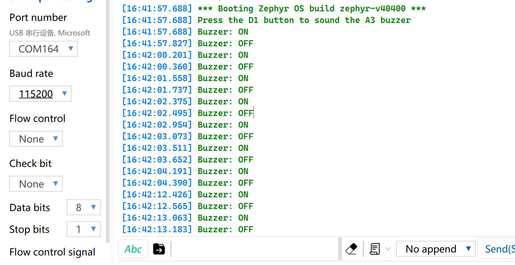
When the Button on the Seeed Studio Expansion Board Base for XIAO is pressed, the buzzer will sound. Open the Serial Monitor and set the baud rate to 115200, and the corresponding status will be printed.
Analog
Analog I/O is based on an Analog-to-Digital Converter (ADC) and is primarily used to capture continuous analog voltage signals output by external sensors. After obtaining the raw digital sampling values (Raw Data), they can be mapped to actual engineering measurement values using specific linear or nonlinear conversion algorithms. This function is widely used in scenarios such as battery voltage sampling and real-time monitoring of physical quantities including soil moisture and ambient temperature.
Hardware Preparation
| Seeed Studio XIAO STM32C5 | Seeed Studio Grove Base for XIAO | Grove - Capacitive Soil Moisture Sensor |
|---|---|---|
| |  |
Software Preparation
- Modify the
app.overlayfile. In the XIAO STM32C5 board-level DTS, A0 is already fully configured as PA0, ADC1 channel 0, with 12-bit resolution. Therefore, inapp.overlay,zephyr,usershould reference ADC1 channel 0.
/ {
	zephyr,user {
		io-channels = <&adc1 0>;
	};
};
- Modify the
prj.conffile to enable ADC-related configurations.
CONFIG_ADC=y
- Modify main.c Program.
main.c
#include <zephyr/kernel.h>
#include <zephyr/drivers/adc.h>
#include <zephyr/sys/printk.h>

static const struct adc_dt_spec adc_ch =
	ADC_DT_SPEC_GET(DT_PATH(zephyr_user));

int main(void)
{
	int ret;
	int16_t buffer;
	struct adc_sequence sequence = {
		.buffer = &buffer,
		.buffer_size = sizeof(buffer),
	};

	if (!adc_is_ready_dt(&adc_ch)) {
		printk("ADC not ready\n");
		return -1;
	}

	ret = adc_channel_setup_dt(&adc_ch);
	if (ret < 0) {
		printk("ADC channel setup failed: %d\n", ret);
		return ret;
	}

	adc_sequence_init_dt(&adc_ch, &sequence);
	printk("A0 ADC example started\n");

	while (1) {
		ret = adc_read_dt(&adc_ch, &sequence);
		if (ret < 0) {
			printk("ADC read error: %d\n", ret);
		} else {
			printk("ADC raw: %d\n", buffer);
		}

		k_msleep(500);
	}
}
Result
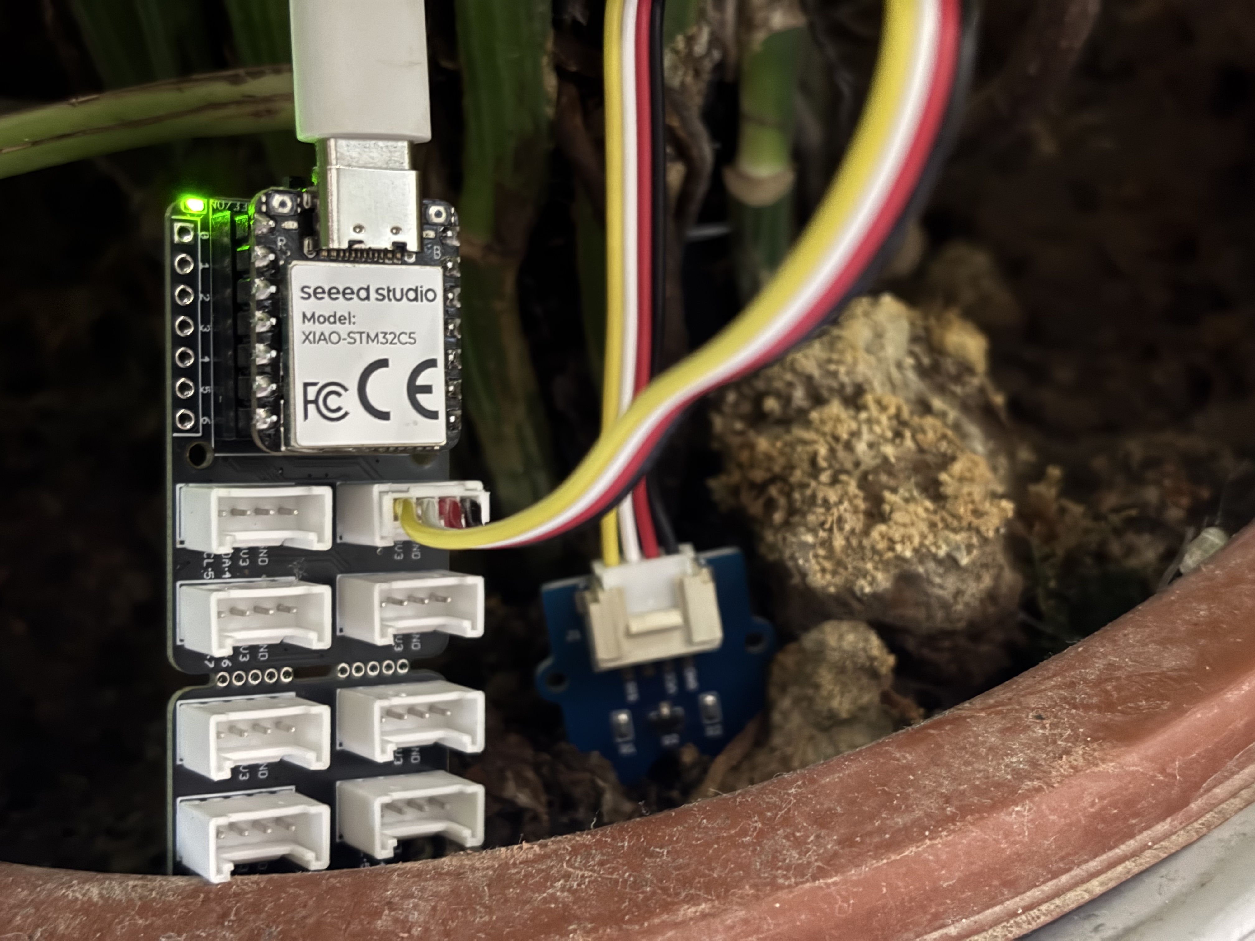
After flashing the program, insert the Grove-Capacitive Soil Moisture Sensor into household potted plants.
Open the serial port assistant on your computer and observe the output values.
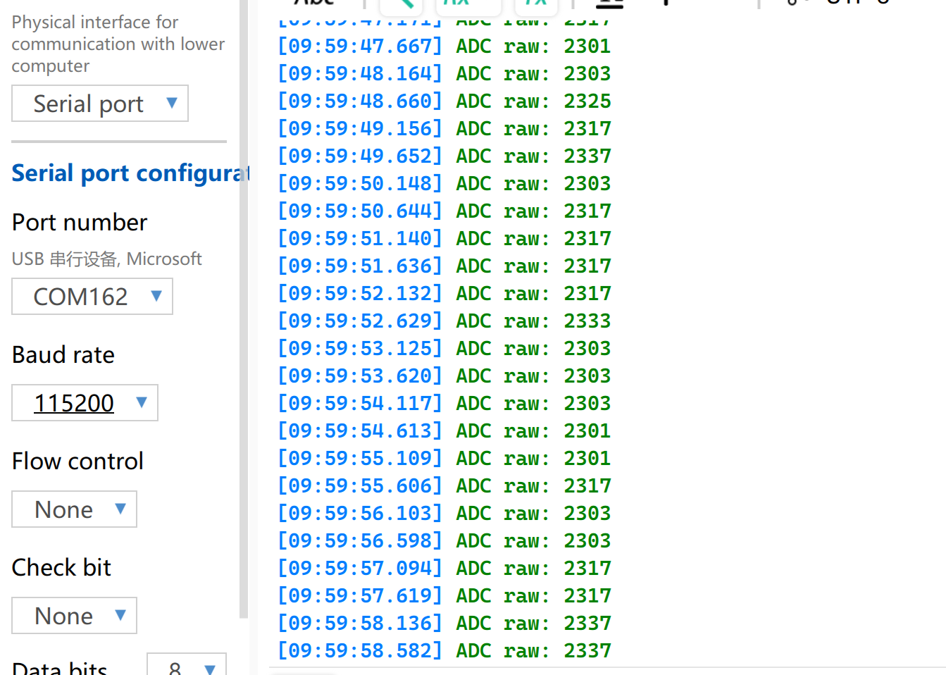
Voltage Reference Reading Table
| Status | Sensor Output Voltage | ADC Raw Value |
|---|---|---|
| In air (Dry) | ~2.0–2.4V | ~3400–4095 |
| In moist soil | ~1.3–1.8V | ~2200–3000 |
| Fully immersed in water | ~0.8–1.2V | ~1365–2048 |
Measurement results may vary under different environmental conditions. Please refer to the actual measured values.
UART
Universal Asynchronous Receiver/Transmitter (UART) is a standard asynchronous serial communication protocol. It does not require external clock signals for synchronization, and realizes asynchronous data transmission and reception relying on the baud rate preset by both communication sides. In terms of physical wiring, a full-duplex data link can be established simply by cross-connecting the TX and RX pins of devices and connecting their grounds together. Featuring minimal hardware cost and support for simultaneous sending and receiving, UART is widely adopted in embedded systems for console log output, modular peripheral debugging and low-bandwidth point-to-point data communication.
Hardware Preparation
| Seeed Studio XIAO STM32C5 | USB to TTL Converter |
|---|---|
|  |
Software Preparation
- Modify app.overlay. On the XIAO STM32C5, D6 corresponds to PA9 / USART1_TX, and D7 corresponds to PA10 / USART1_RX. The corresponding DeviceTree node is usart1. Set the default baud rate to 115200.
/ {
	chosen {
		zephyr,console = &usart1;
		zephyr,shell-uart = &usart1;
	};
};
- Modify prj.conf to enable serial console support.
CONFIG_SERIAL=y
CONFIG_CONSOLE=y
CONFIG_UART_CONSOLE=y
CONFIG_UART_INTERRUPT_DRIVEN=y
CONFIG_PRINTK=y
- The program prints the UART pin mapping at startup, echoes received data, and prints a periodic running-status message.
main.c
#include <zephyr/kernel.h>
#include <zephyr/device.h>
#include <zephyr/drivers/uart.h>
#include <zephyr/sys/printk.h>

#define RX_BUFFER_SIZE 128
#define RX_TIMEOUT_MS  50

static const struct device *const uart = DEVICE_DT_GET(DT_NODELABEL(usart1));
K_MSGQ_DEFINE(rx_msgq, sizeof(uint8_t), RX_BUFFER_SIZE, 1);

static void uart_rx_isr(const struct device *dev, void *user_data)
{
	uint8_t data[16];
	int length;

	ARG_UNUSED(user_data);

	if (!uart_irq_update(dev)) {
		return;
	}

	while (uart_irq_rx_ready(dev)) {
		length = uart_fifo_read(dev, data, sizeof(data));
		if (length <= 0) {
			break;
		}

		for (int i = 0; i < length; i++) {
			(void)k_msgq_put(&rx_msgq, &data[i], K_NO_WAIT);
		}
	}
}

int main(void)
{
	char rx_buffer[RX_BUFFER_SIZE];
	size_t rx_length = 0;
	int64_t last_rx_time = 0;
	int64_t last_debug_time = k_uptime_get();

	if (!device_is_ready(uart)) {
		return -1;
	}

	if (uart_irq_callback_user_data_set(uart, uart_rx_isr, NULL) < 0) {
		return -1;
	}

	uart_irq_rx_enable(uart);

	printk("\r\nXIAO STM32C5 UART demo\r\n");
	printk("D6: TX, D7: RX, 115200 8N1\r\n");
	printk("Type a character to test RX and echo.\r\n");

	while (1) {
		uint8_t data;
		int64_t now;

		while (k_msgq_get(&rx_msgq, &data, K_NO_WAIT) == 0) {
			last_rx_time = k_uptime_get();

			if (data == '\r' || data == '\n') {
				if (rx_length > 0) {
					rx_buffer[rx_length] = '\0';
					printk("RX: %s\r\n", rx_buffer);
					rx_length = 0;
				}
			} else if (rx_length < RX_BUFFER_SIZE - 1) {
				rx_buffer[rx_length++] = (char)data;
			}
		}

		now = k_uptime_get();

		/* Also print strings sent without a trailing CR/LF. */
		if (rx_length > 0 && now - last_rx_time >= RX_TIMEOUT_MS) {
			rx_buffer[rx_length] = '\0';
			printk("RX: %s\r\n", rx_buffer);
			rx_length = 0;
		}

		if (now - last_debug_time >= 1000) {
			printk("UART debug: system running\r\n");
			last_debug_time = now;
		}

		k_msleep(1);
	}
}
Result
- Wire according to the table order
| XIAO STM32C5 | CH340 |
|---|---|
| GND | GND |
| D6 - TX | RX |
| D7 - RX | TX |
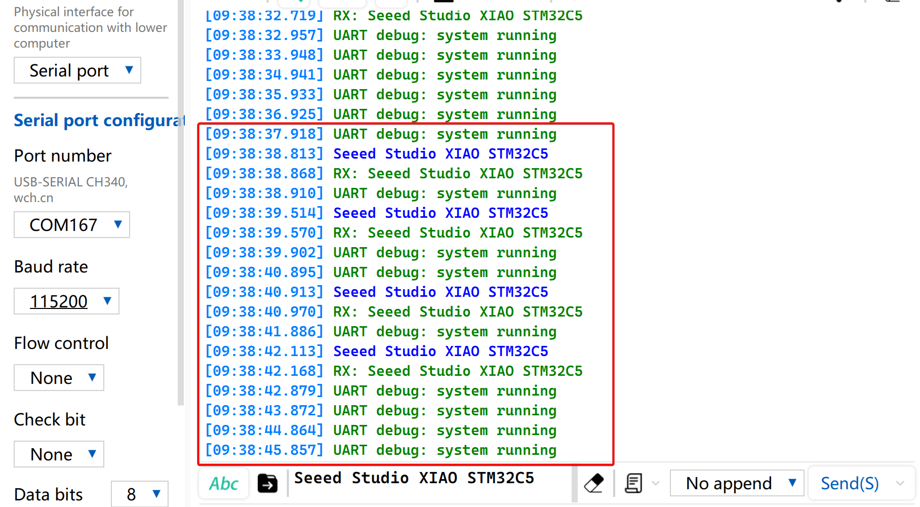
- You can use a serial monitor to view runtime information. You can also send data through the serial port, and the received data will be printed to the console.
I2C
I2C is a synchronous, half-duplex data communication protocol. It enables multi-device connection through addressing via the SCL clock line and SDA data line, and is commonly used to read data from sensors requiring relatively high transmission rates, such as IMUs and temperature/humidity sensors, or for OLED display output.
Hardware Preparation
| Seeed Studio XIAO STM32C5 | Seeed Studio Expansion Board Base for XIAO |
|---|---|
| |
Software Preparation
- On the XIAO STM32C5, D4 corresponds to PB7 / I2C1_SDA, and D5 corresponds to PB6 / I2C1_SCL. Since I2C1 is already enabled in the board-level DTS, add an SSD1306 display node at I2C address 0x3C. Modify app.overlay as follows:
/ {
	chosen {
		zephyr,display = &oled;
	};
};

&i2c1 {
	oled: ssd1306@3c {
		compatible = "solomon,ssd1306";
		reg = <0x3c>;
		width = <128>;
		height = <64>;
		segment-offset = <0>;
		page-offset = <0>;
		display-offset = <0>;
		multiplex-ratio = <63>;
		segment-remap;
		com-invdir;
		prechargep = <0x22>;
	};
};
- Modify the
prj.conffile to enable I2C and display-related configurations.
CONFIG_DISPLAY=y
CONFIG_CHARACTER_FRAMEBUFFER=y
CONFIG_HEAP_MEM_POOL_SIZE=2048
- Write the main function to set the display position and functions for the string.
main.c
#include <zephyr/device.h>
#include <zephyr/display/cfb.h>
#include <zephyr/sys/printk.h>

int main(void)
{
	const struct device *display = DEVICE_DT_GET(DT_CHOSEN(zephyr_display));

	if (!device_is_ready(display)) {
		printk("OLED not ready\n");
		return -1;
	}

	if (cfb_framebuffer_init(display)) {
		return -1;
	}

	cfb_framebuffer_clear(display, true);
	cfb_framebuffer_set_font(display, 0);
	cfb_print(display, "XIAO STM32C5", 4, 8);
	cfb_print(display, "Hello World", 9, 32);
	cfb_framebuffer_finalize(display);
	display_blanking_off(display);

	return 0;
}
Result
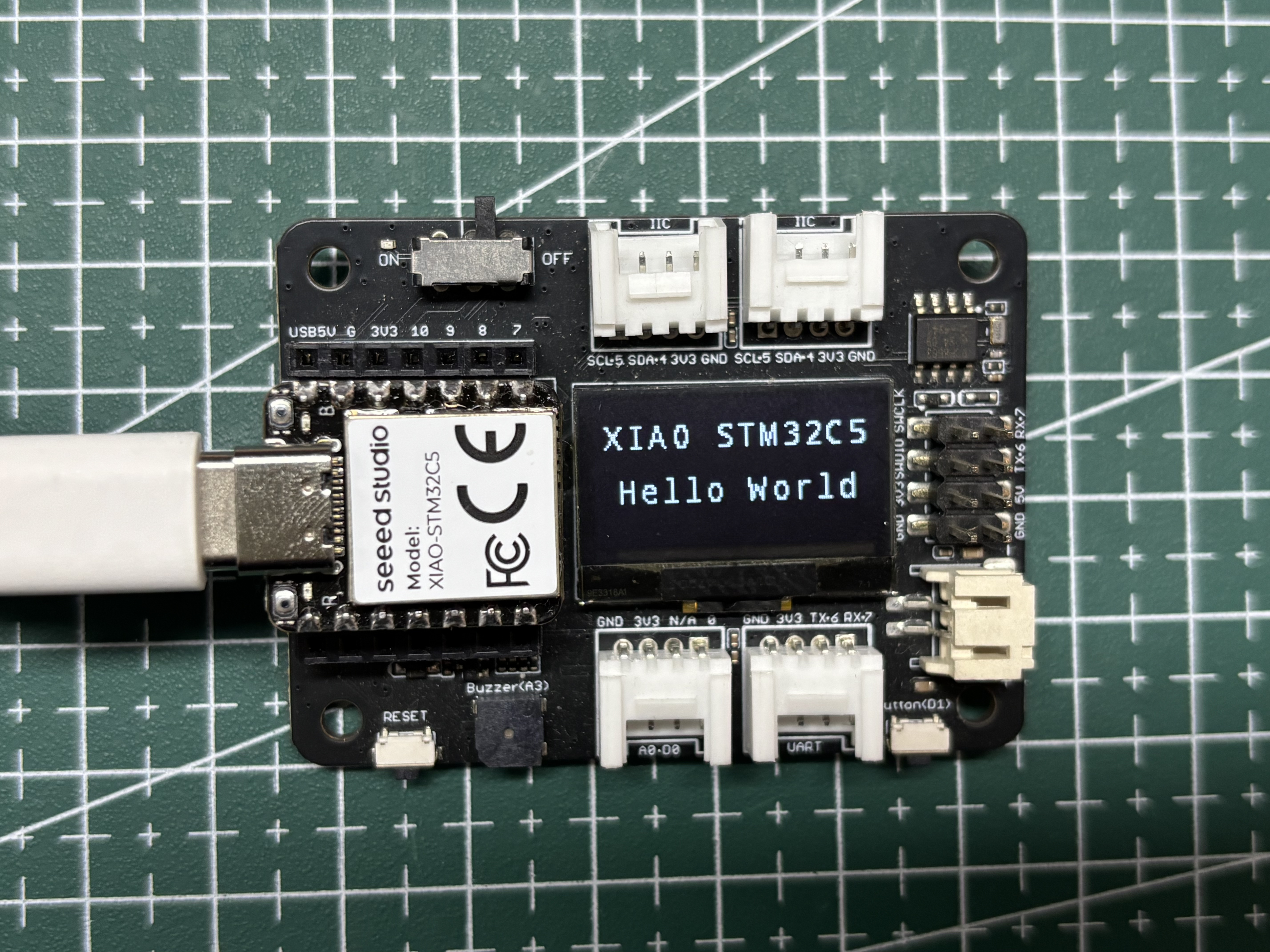
After the program runs, the OLED displays XIAO STM32C5 Hello World.
SPI
SPI is a high-speed, synchronous and full-duplex communication protocol. Unlike asynchronous communication, SPI relies on a dedicated SCLK clock line for precise data synchronization. It generally adopts the classic four-wire hardware topology consisting of MOSI, MISO and chip select CS/SS pins. Equipped with independent data sending and receiving channels and high bus clock frequency, SPI delivers excellent data throughput. It is widely used in peripheral driving scenarios demanding high bandwidth, such as mass storage devices including Flash and SD cards, high-resolution and high-refresh-rate screen displays, and high-frequency sampling sensors.
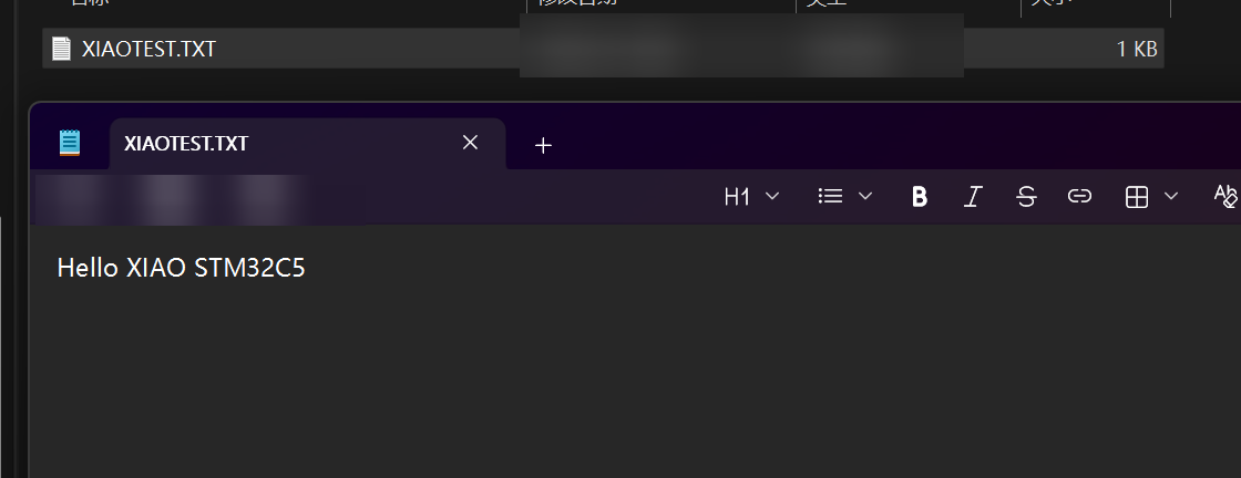
Next, an SD card example will be demonstrated: reading the size of the SD card and writing a file named XIAOTEST.TXT to it, with the content Hello XIAO STM32C5.
Hardware Preparation
| Seeed Studio XIAO STM32C5 | Seeed Studio Expansion Board Base for XIAO |
|---|---|
| |
In addition, you also need to prepare an SD card formatted as FAT32, with a storage capacity of 32 GB or less.
Software Preparation
- The default SPI bus pins of the XIAO STM32C5 are D8 - SPI_SCK, D9 - SPI_MISO, and D10 - SPI_MOSI. The corresponding node in the board-level DTS is
SPI3. In addition, a CS chip-select pin needs to be selected, and D2 is selected here.
app.overlay
#include <zephyr/dt-bindings/gpio/gpio.h>

/ {
	chosen {
		zephyr,display = &oled;
	};
};

&i2c1 {
	oled: ssd1306@3c {
		compatible = "solomon,ssd1306";
		reg = <0x3c>;
		width = <128>;
		height = <64>;
		segment-offset = <0>;
		page-offset = <0>;
		display-offset = <0>;
		multiplex-ratio = <63>;
		segment-remap;
		com-invdir;
		prechargep = <0x22>;
	};
};

&spi3 {
	cs-gpios = <&gpioa 2 GPIO_ACTIVE_LOW>; /* D2: SD card CS */

	sdhc0: sdhc@0 {
		compatible = "zephyr,sdhc-spi-slot";
		reg = <0>;
		status = "okay";
		spi-max-frequency = <8000000>;

		mmc {
			compatible = "zephyr,sdmmc-disk";
			disk-name = "SD";
			status = "okay";
		};
	};
};
- Modify prj.conf to enable SPI-related configurations.
CONFIG_DISK_ACCESS=y
CONFIG_FILE_SYSTEM=y
CONFIG_FAT_FILESYSTEM_ELM=y
CONFIG_SDHC=y
CONFIG_SDMMC_SUBSYS=y

CONFIG_DISPLAY=y
CONFIG_CHARACTER_FRAMEBUFFER=y

CONFIG_MAIN_STACK_SIZE=4096
CONFIG_HEAP_MEM_POOL_SIZE=4096
CONFIG_PRINTK=y
- Modify the main.c program.
main.c
/*
* XIAO STM32C5 SD card read/write example.
*
* SD card (SPI3, FAT32):
* D8 - SCK
* D9 - MISO
* D10 - MOSI
* D2 - CS
*
* 0.96-inch SSD1306 OLED (128x64, I2C address 0x3C):
* D4 - SDA
* D5 - SCL
*
* The example waits 500 ms after power-on, reads the SD card capacity,
* creates /XIAOTEST.TXT, writes "Hello XIAO STM32C5", then reads the file
* back for verification. Card size, write progress, and the final result
* are displayed on the OLED and printed through the USB CDC console.
*/
#include <errno.h>
#include <string.h>
#include <zephyr/device.h>
#include <zephyr/display/cfb.h>
#include <zephyr/fs/fs.h>
#include <zephyr/kernel.h>
#include <zephyr/storage/disk_access.h>
#include <zephyr/sys/printk.h>
#include <ff.h>
#define DISK_NAME "SD"
#define MOUNT_POINT "/SD:"
#define TEST_FILE MOUNT_POINT "/XIAOTEST.TXT"
#define TEST_TEXT "Hello XIAO STM32C5"
static const struct device *const oled = DEVICE_DT_GET(DT_CHOSEN(zephyr_display));
static FATFS fat_fs;
static struct fs_mount_t mount = {
.type = FS_FATFS,
.fs_data = &fat_fs,
.mnt_point = MOUNT_POINT,
};
static void oled_show(const char *line1, const char *line2,
const char *line3, const char *line4)
{
cfb_framebuffer_clear(oled, false);
cfb_print(oled, line1, 0, 0);
cfb_print(oled, line2, 0, 16);
cfb_print(oled, line3, 0, 32);
cfb_print(oled, line4, 0, 48);
cfb_framebuffer_finalize(oled);
}
int main(void)
{
uint32_t sector_count;
uint32_t sector_size;
uint64_t size_mb;
char size_line[24];
char readback[sizeof(TEST_TEXT)] = { 0 };
struct fs_file_t file;
int ret;
/* Allow the USB CDC console time to become available after power-on. */
k_msleep(500);
printk("\n=== XIAO STM32C5 SD Card Test ===\n");
printk("SD: D8=SCK, D9=MISO, D10=MOSI, D2=CS\n");
printk("OLED: D4=SDA, D5=SCL\n");
if (!device_is_ready(oled) || cfb_framebuffer_init(oled) != 0) {
printk("OLED initialization failed\n");
return -1;
}
cfb_framebuffer_set_font(oled, 0);
display_blanking_off(oled);
oled_show("SD Card Test", "Initializing...", "", "");
/* Initialize the SD card and read its physical capacity. */
ret = disk_access_ioctl(DISK_NAME, DISK_IOCTL_CTRL_INIT, NULL);
if (ret != 0) {
oled_show("SD Card Test", "SD init FAILED", "Check card/wires", "");
printk("SD card initialization failed: %d\n", ret);
return ret;
}
printk("SD card initialized\n");
ret = disk_access_ioctl(DISK_NAME, DISK_IOCTL_GET_SECTOR_COUNT,
§or_count);
ret |= disk_access_ioctl(DISK_NAME, DISK_IOCTL_GET_SECTOR_SIZE,
§or_size);
if (ret != 0) {
oled_show("SD Card Test", "Read size FAILED", "", "");
printk("Failed to read SD card capacity: %d\n", ret);
return ret;
}
size_mb = ((uint64_t)sector_count * sector_size) / (1024U * 1024U);
snprintk(size_line, sizeof(size_line), "Size: %llu MB", size_mb);
oled_show("SD Card Test", size_line, "Mounting FAT32", "");
printk("SD card size: %llu MB\n", size_mb);
printk("Mounting FAT32 file system...\n");
ret = fs_mount(&mount);
if (ret != 0) {
oled_show("SD Card Test", size_line, "Mount FAILED", "Use FAT32 card");
printk("FAT32 mount failed: %d\n", ret);
return ret;
}
printk("FAT32 mounted\n");
/* Create or replace the test file and write the requested text. */
oled_show("SD Card Test", size_line, "Writing file...", "");
printk("Writing %s...\n", TEST_FILE);
fs_file_t_init(&file);
ret = fs_open(&file, TEST_FILE, FS_O_CREATE | FS_O_WRITE | FS_O_TRUNC);
if (ret == 0) {
ret = fs_write(&file, TEST_TEXT, sizeof(TEST_TEXT) - 1);
if (ret == sizeof(TEST_TEXT) - 1) {
ret = fs_sync(&file);
} else if (ret >= 0) {
ret = -EIO;
}
fs_close(&file);
}
/* Read the file back so SUCCESS means the stored data was verified. */
if (ret == 0) {
fs_file_t_init(&file);
ret = fs_open(&file, TEST_FILE, FS_O_READ);
if (ret == 0) {
ret = fs_read(&file, readback, sizeof(readback) - 1);
fs_close(&file);
if (ret == sizeof(TEST_TEXT) - 1 &&
strcmp(readback, TEST_TEXT) == 0) {
ret = 0;
} else if (ret >= 0) {
ret = -EIO;
}
}
}
fs_unmount(&mount);
if (ret == 0) {
oled_show("SD Card Test", size_line, "Write: SUCCESS", "File verified");
printk("Write successful: %s\n", TEST_TEXT);
printk("Readback verification successful\n");
} else {
oled_show("SD Card Test", size_line, "Write: FAILED", "Check SD card");
printk("SD card write failed: %d\n", ret);
}
return ret;
}
Result
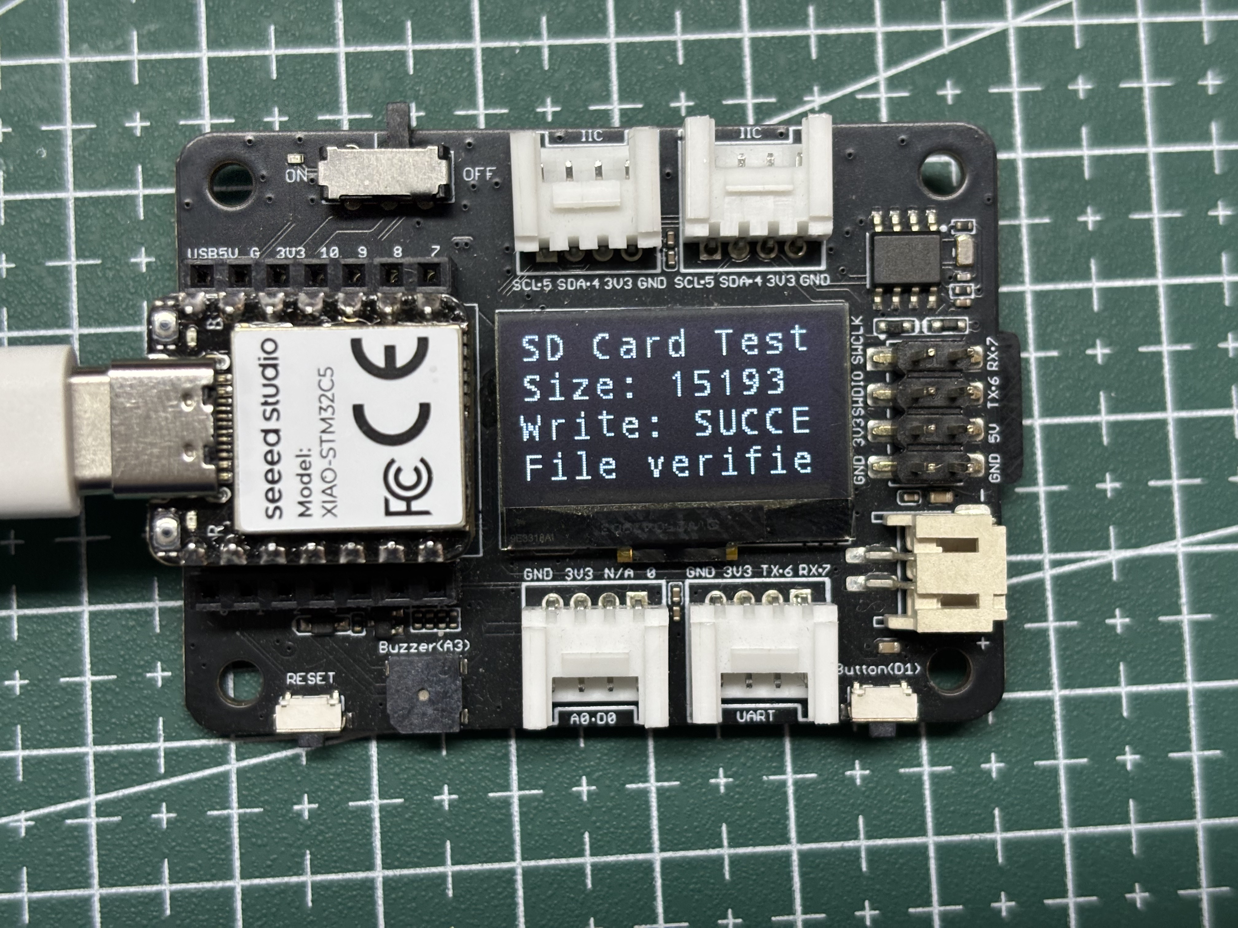
- The screen will display information such as the SD card mount status, the SD card capacity, and whether the file was written successfully.
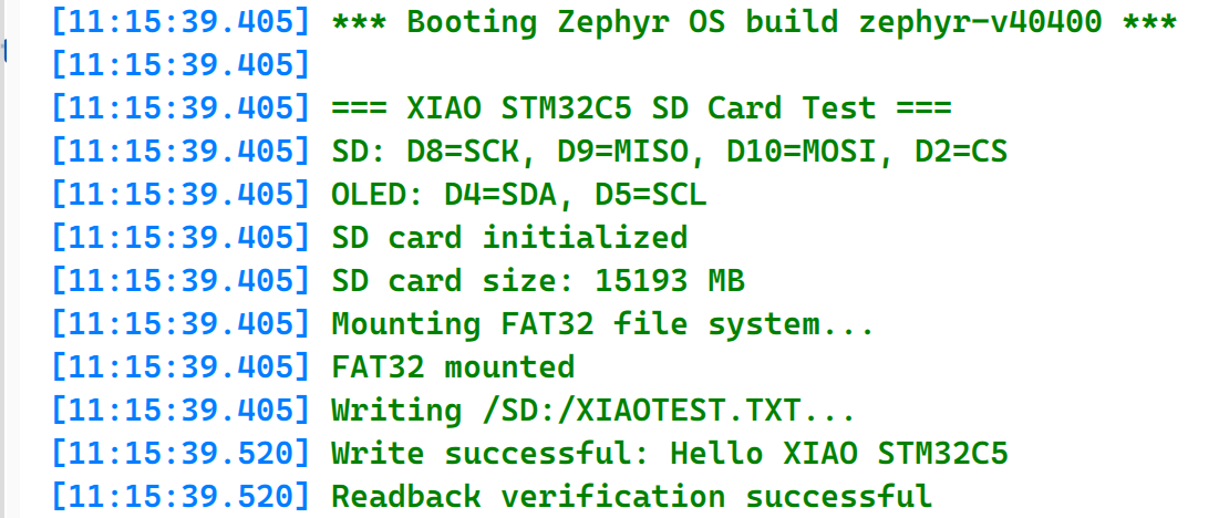
- Open the Serial Monitor to view the file write information.
- Remove the SD card and insert it into a card reader connected to your computer to inspect the written file.
RTC
RTC (Real-Time Clock) is a low-power hardware timing peripheral used to continuously maintain accurate time and calendar information. It normally operates from an independent low-frequency clock source, such as a 32.768 kHz crystal oscillator, and can continue running through the backup power domain when the main system is powered off. RTC peripherals commonly support seconds, minutes, hours, dates, weekdays, months and years, as well as alarm, periodic wake-up and timestamp functions. RTC is widely used in applications requiring long-term timekeeping, scheduled wake-up, event recording and low-power operation, such as data loggers, industrial controllers, smart home devices and portable instruments.
The Round Display for Seeed Studio XIAO features an on‑board RTC circuit. The following demonstrates the RTC clock function working with the XIAO STM32C5.
Hardware Preparation
| Seeed Studio XIAO STM32C5 | Round Display for Seeed Studio XIAO |
|---|---|
|  |
Software Preparation
- Modify app.overlay: The Round Display for Seeed Studio XIAO features a 240 × 240 GC9A01 LCD. On the XIAO STM32C5, the LCD uses D8 (SCK), D10 (MOSI), D1 (CS), and D3 (DC). Since D8 and D10 are mapped to SPI3, SPI3 must be enabled and a GC9A01 display node must be added. The onboard PCF8563 RTC communicates over I²C using D4 (SDA) and D5 (SCL), which are mapped to I2C1. Therefore, I2C1 must also be enabled and a PCF8563 RTC device node must be added.
app.overlay
#include <freq.h>
#include <zephyr/dt-bindings/display/panel.h>
#include <zephyr/dt-bindings/gpio/gpio.h>

/ {
	chosen {
		zephyr,display = &gc9a01_round_display;
	};

	aliases {
		rtc = &pcf8563_round_display;
	};

	backlight_leds {
		compatible = "gpio-leds";

		display_backlight: backlight {
			gpios = <&xiao_d 6 GPIO_ACTIVE_HIGH>;
		};
	};

	round_display_mipi_dbi {
		compatible = "zephyr,mipi-dbi-spi";
		spi-dev = <&spi3>;
		dc-gpios = <&xiao_d 3 GPIO_ACTIVE_HIGH>;
		write-only;
		#address-cells = <1>;
		#size-cells = <0>;

		gc9a01_round_display: gc9a01@0 {
			compatible = "galaxycore,gc9x01x";
			reg = <0>;
			status = "okay";
			mipi-max-frequency = <DT_FREQ_M(8)>;
			pixel-format = <PANEL_PIXEL_FORMAT_RGB_565>;
			width = <240>;
			height = <240>;
			display-inversion;
		};
	};
};

&usart1 {
	/* Release D6 (PA9) for the display backlight. */
	status = "disabled";
};

&i2c1 {
	clock-frequency = <I2C_BITRATE_FAST>;

	pcf8563_round_display: pcf8563@51 {
		compatible = "nxp,pcf8563";
		reg = <0x51>;
		status = "okay";
	};
};

&spi3 {
	/* D8=PE2 SCK, D9=PB0 MISO, D10=PB15 MOSI. */
	status = "okay";
	cs-gpios = <&xiao_d 1 GPIO_ACTIVE_LOW>;
};
- Modify prj.conf to enable configurations.
CONFIG_GPIO=y
CONFIG_SPI=y
CONFIG_I2C=y
CONFIG_RTC=y
CONFIG_RTC_PCF8563=y

CONFIG_DISPLAY=y
CONFIG_MIPI_DBI=y

CONFIG_MAIN_STACK_SIZE=4096
CONFIG_PRINTK=y
- Write main.c to read the PCF8563 RTC and display the date, time, and weekday on the round screen.
main.c
/*
 * Copyright (c) 2026 Seeed Technology Co., Ltd.
 * SPDX-License-Identifier: Apache-2.0
 *
 * RTC clock demo for XIAO STM32C5 and Round Display for XIAO.
 *
 * Display: GC9A01, 240x240, hardware SPI3
 *          (D8 SCK, D10 MOSI, D1 CS, D3 DC)
 *          D8=PE2, D9=PB0 and D10=PB15.
 * RTC:     PCF8563 on the Round Display (D4 SDA, D5 SCL)
 * BL:      D6
 *
 * Reads the PCF8563 once per second and shows the date, time and weekday.
 * An invalid RTC value is initialized to 2026-06-16 12:00:00.
 */

#include <stdbool.h>
#include <zephyr/device.h>
#include <zephyr/drivers/display.h>
#include <zephyr/drivers/gpio.h>
#include <zephyr/drivers/rtc.h>
#include <zephyr/kernel.h>
#include <zephyr/sys/printk.h>

#define LCD_WIDTH  240
#define LCD_HEIGHT 240

#define COLOR_WHITE  0xFFFFU
#define COLOR_GREEN  0x07E0U
#define COLOR_CYAN   0x07FFU
#define COLOR_NAVY   0x0842U
#define COLOR_GRAY   0x8410U

static const struct device *const display =
	DEVICE_DT_GET(DT_CHOSEN(zephyr_display));
static const struct device *const rtc = DEVICE_DT_GET(DT_ALIAS(rtc));
static const struct gpio_dt_spec backlight =
	GPIO_DT_SPEC_GET(DT_NODELABEL(display_backlight), gpios);

/* Full RGB565 frame buffer, kept global to avoid using the thread stack. */
static uint16_t framebuffer[LCD_WIDTH * LCD_HEIGHT];
static const struct display_buffer_descriptor frame_desc = {
	.buf_size = sizeof(framebuffer),
	.width = LCD_WIDTH,
	.height = LCD_HEIGHT,
	.pitch = LCD_WIDTH,
};

static uint16_t rgb565_be(uint16_t color)
{
	return (uint16_t)((color >> 8) | (color << 8));
}

static void set_pixel(int x, int y, uint16_t color)
{
	if (x >= 0 && x < LCD_WIDTH && y >= 0 && y < LCD_HEIGHT) {
		framebuffer[y * LCD_WIDTH + x] = rgb565_be(color);
	}
}

static void fill_rect(int x, int y, int width, int height, uint16_t color)
{
	for (int py = y; py < y + height; py++) {
		for (int px = x; px < x + width; px++) {
			set_pixel(px, py, color);
		}
	}
}

static void draw_circle(int cx, int cy, int radius, uint16_t color)
{
	int x = radius;
	int y = 0;
	int error = 1 - radius;

	while (x >= y) {
		set_pixel(cx + x, cy + y, color);
		set_pixel(cx + y, cy + x, color);
		set_pixel(cx - y, cy + x, color);
		set_pixel(cx - x, cy + y, color);
		set_pixel(cx - x, cy - y, color);
		set_pixel(cx - y, cy - x, color);
		set_pixel(cx + y, cy - x, color);
		set_pixel(cx + x, cy - y, color);
		y++;
		if (error < 0) {
			error += 2 * y + 1;
		} else {
			x--;
			error += 2 * (y - x) + 1;
		}
	}
}

static void draw_filled_circle(int cx, int cy, int radius, uint16_t color)
{
	for (int y = -radius; y <= radius; y++) {
		for (int x = -radius; x <= radius; x++) {
			if (x * x + y * y <= radius * radius) {
				set_pixel(cx + x, cy + y, color);
			}
		}
	}
}

static void draw_digit(int x, int y, int width, int height, int thickness,
		       int digit, uint16_t color)
{
	static const uint8_t segments[10] = {
		0x3F, 0x06, 0x5B, 0x4F, 0x66,
		0x6D, 0x7D, 0x07, 0x7F, 0x6F
	};
	uint8_t mask = segments[digit];
	int half = height / 2;

	if (mask & BIT(0)) {
		fill_rect(x + thickness, y, width - 2 * thickness, thickness, color);
	}
	if (mask & BIT(1)) {
		fill_rect(x + width - thickness, y + thickness,
			  thickness, half - thickness, color);
	}
	if (mask & BIT(2)) {
		fill_rect(x + width - thickness, y + half,
			  thickness, half - thickness, color);
	}
	if (mask & BIT(3)) {
		fill_rect(x + thickness, y + height - thickness,
			  width - 2 * thickness, thickness, color);
	}
	if (mask & BIT(4)) {
		fill_rect(x, y + half, thickness, half - thickness, color);
	}
	if (mask & BIT(5)) {
		fill_rect(x, y + thickness, thickness, half - thickness, color);
	}
	if (mask & BIT(6)) {
		fill_rect(x + thickness, y + half - thickness / 2,
			  width - 2 * thickness, thickness, color);
	}
}

static void draw_colon(int x, int y, int size, uint16_t color)
{
	fill_rect(x, y, size, size, color);
	fill_rect(x, y + 23, size, size, color);
}

static int write_frame(void)
{
	return display_write(display, 0, 0, &frame_desc, framebuffer);
}

static void clear_frame(uint16_t color)
{
	uint16_t value = rgb565_be(color);

	for (int i = 0; i < LCD_WIDTH * LCD_HEIGHT; i++) {
		framebuffer[i] = value;
	}
}

static bool rtc_time_valid(const struct rtc_time *time)
{
	return time->tm_year >= (2024 - 1900) &&
	       time->tm_year <= (2099 - 1900) &&
	       time->tm_mon >= 0 && time->tm_mon <= 11 &&
	       time->tm_mday >= 1 && time->tm_mday <= 31 &&
	       time->tm_hour >= 0 && time->tm_hour <= 23 &&
	       time->tm_min >= 0 && time->tm_min <= 59 &&
	       time->tm_sec >= 0 && time->tm_sec <= 59;
}

static int render_clock(const struct rtc_time *time)
{
	int year = time->tm_year + 1900;
	int month = time->tm_mon + 1;
	int day = time->tm_mday;
	static const uint8_t date_x[] = { 48, 62, 76, 90, 118, 132, 160, 174 };
	static const uint8_t time_x[] = { 24, 54, 96, 126, 168, 198 };
	uint8_t date_digits[] = {
		(year / 1000) % 10, (year / 100) % 10,
		(year / 10) % 10, year % 10,
		month / 10, month % 10, day / 10, day % 10
	};
	uint8_t time_digits[] = {
		time->tm_hour / 10, time->tm_hour % 10,
		time->tm_min / 10, time->tm_min % 10,
		time->tm_sec / 10, time->tm_sec % 10
	};

	clear_frame(COLOR_NAVY);
	draw_circle(120, 120, 116, COLOR_CYAN);
	draw_circle(120, 120, 115, COLOR_CYAN);
	fill_rect(75, 39, 90, 3, COLOR_CYAN);

	for (int i = 0; i < ARRAY_SIZE(date_digits); i++) {
		draw_digit(date_x[i], 54, 12, 24, 3,
			   date_digits[i], COLOR_GREEN);
	}
	fill_rect(106, 65, 8, 3, COLOR_GREEN);
	fill_rect(148, 65, 8, 3, COLOR_GREEN);

	for (int i = 0; i < ARRAY_SIZE(time_digits); i++) {
		draw_digit(time_x[i], 94, 26, 54, 5,
			   time_digits[i], COLOR_WHITE);
	}
	draw_colon(84, 107, 6, COLOR_CYAN);
	draw_colon(156, 107, 6, COLOR_CYAN);

	for (int i = 0; i < 7; i++) {
		uint16_t color = (i == time->tm_wday) ? COLOR_GREEN : COLOR_GRAY;
		draw_filled_circle(75 + i * 15, 188, 4, color);
	}
	fill_rect(88, 207, 64, 3, COLOR_CYAN);

	return write_frame();
}

int main(void)
{
	struct rtc_time now = { 0 };
	int ret;

	if (!gpio_is_ready_dt(&backlight) || !device_is_ready(display) ||
	    !device_is_ready(rtc)) {
		printk("Display, backlight, or RTC device not ready\n");
		return -1;
	}

	ret = gpio_pin_configure_dt(&backlight, GPIO_OUTPUT_ACTIVE);
	if (ret < 0) {
		printk("Cannot enable display backlight: %d\n", ret);
		return ret;
	}

	ret = display_set_pixel_format(display, PIXEL_FORMAT_RGB_565);
	if (ret < 0) {
		printk("Cannot set RGB565 pixel format: %d\n", ret);
		return ret;
	}
	display_blanking_off(display);

	ret = rtc_get_time(rtc, &now);
	if (ret < 0 || !rtc_time_valid(&now)) {
		struct rtc_time initial_time = {
			.tm_year = 2026 - 1900,
			.tm_mon = 5,
			.tm_mday = 16,
			.tm_hour = 12,
			.tm_min = 0,
			.tm_sec = 0,
			.tm_wday = 2,
		};

		ret = rtc_set_time(rtc, &initial_time);
		if (ret < 0) {
			printk("Cannot set RTC time: %d\n", ret);
			return ret;
		}
		printk("RTC initialized to 2026-06-16 12:00:00\n");
	}

	printk("Round Display RTC clock started\n");

	while (1) {
		ret = rtc_get_time(rtc, &now);
		if (ret < 0) {
			printk("Cannot read RTC time: %d\n", ret);
		} else {
			ret = render_clock(&now);
			if (ret < 0) {
				printk("Display write failed: %d\n", ret);
			}
			printk("%04d-%02d-%02d %02d:%02d:%02d\n",
			       now.tm_year + 1900, now.tm_mon + 1, now.tm_mday,
			       now.tm_hour, now.tm_min, now.tm_sec);
		}
		k_msleep(1000);
	}
}
Result
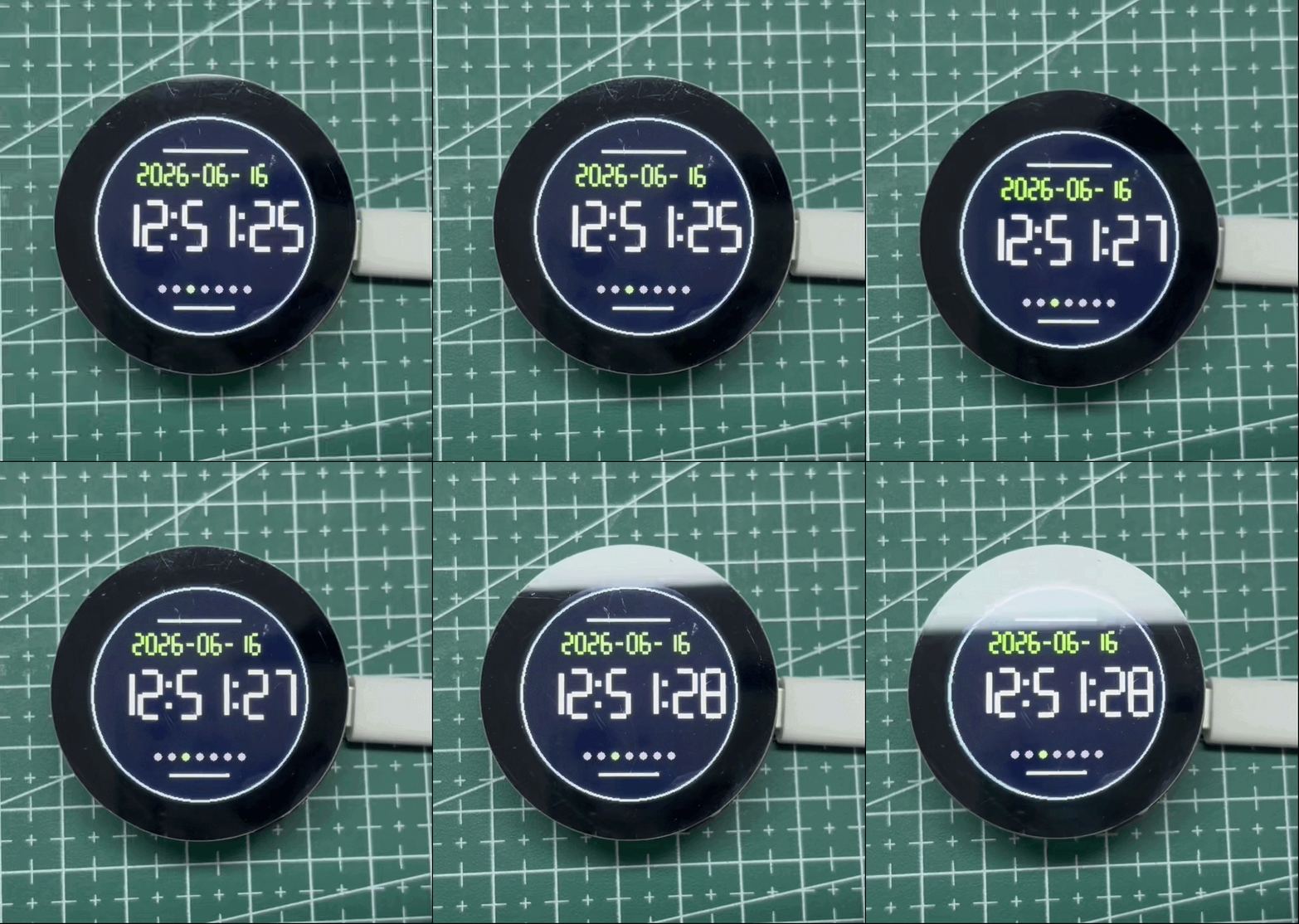
This example sets and reads the date and time from the PCF8563 RTC on the Round Display over I²C and shows the result on the circular LCD. Without an RTC backup battery, the PCF8563 keeps time while the system is powered, but the time is not guaranteed to be retained after power is removed. With a CR927 coin-cell battery installed, the RTC can continue running while the main power is disconnected and retain the correct time when the system is powered on again. If the RTC contains no valid time, the example initializes it to 2026-06-16 12:00:00 for demonstration. Set the RTC to the current time separately; this example does not synchronize it automatically.
Tech Support & Product Discussion
Thank you for choosing our products! We are here to provide you with different support to ensure that your experience with our products is as smooth as possible. We offer several communication channels to cater to different preferences and needs.