XIAO STM32C5 with MicroPython
Overview
MicroPython is a Python interpreter with support for native code emission for performance-critical code. It provides a subset of core Python 3.6+ features, optimized for microcontrollers and resource-constrained systems. It differs from CPython, and you can read more about the differences in the MicroPython vs CPython differences page.
Hardware Preparation
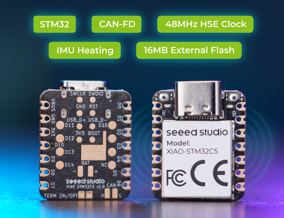
Before you start, you need to prepare an XIAO STM32C5 development board.
| Seeed Studio XIAO STM32C5 |
|---|
 |
Deploying MicroPython Firmware
Update the MicroPython firmware on the XIAO STM32C5 by entering bootloader mode and copying a .uf2 firmware file to the board's USB mass-storage drive.
- Download and extract the XIAO STM32C5 MicroPython firmware archive:
- 📄[Firmware] XIAO STM32C5 MicroPython Firmware
- Connect the XIAO STM32C5 to your computer over USB. Quickly double-press the Reset button to enter bootloader mode. A USB drive named XIAOC5BOOT should appear. Copy micropython-xiao-stm32c5.uf2 from the extracted archive to that drive. The board will reboot automatically after the firmware is installed.
If XIAOC5BOOT does not appear, disconnect and reconnect the USB cable, then double-press Reset again. Make sure the USB cable supports data transfer.
Install Thonny IDE
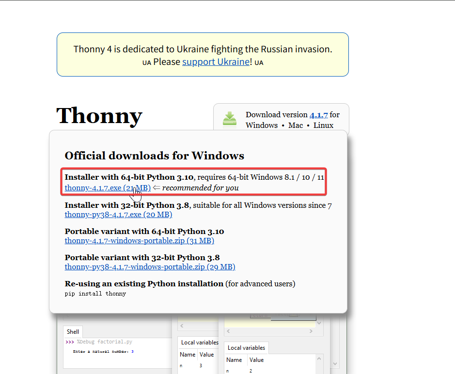
Choose the appropriate version for installation. Here, I am installing it on a Windows system, so I have selected the Windows version.
Follow the instructions for the desired Python version.
Then, simply follow the default steps for configuration.
Interpreter Configuration
- Open Thonny IDE and configure the interpreter and serial port for the XIAO STM32C5.
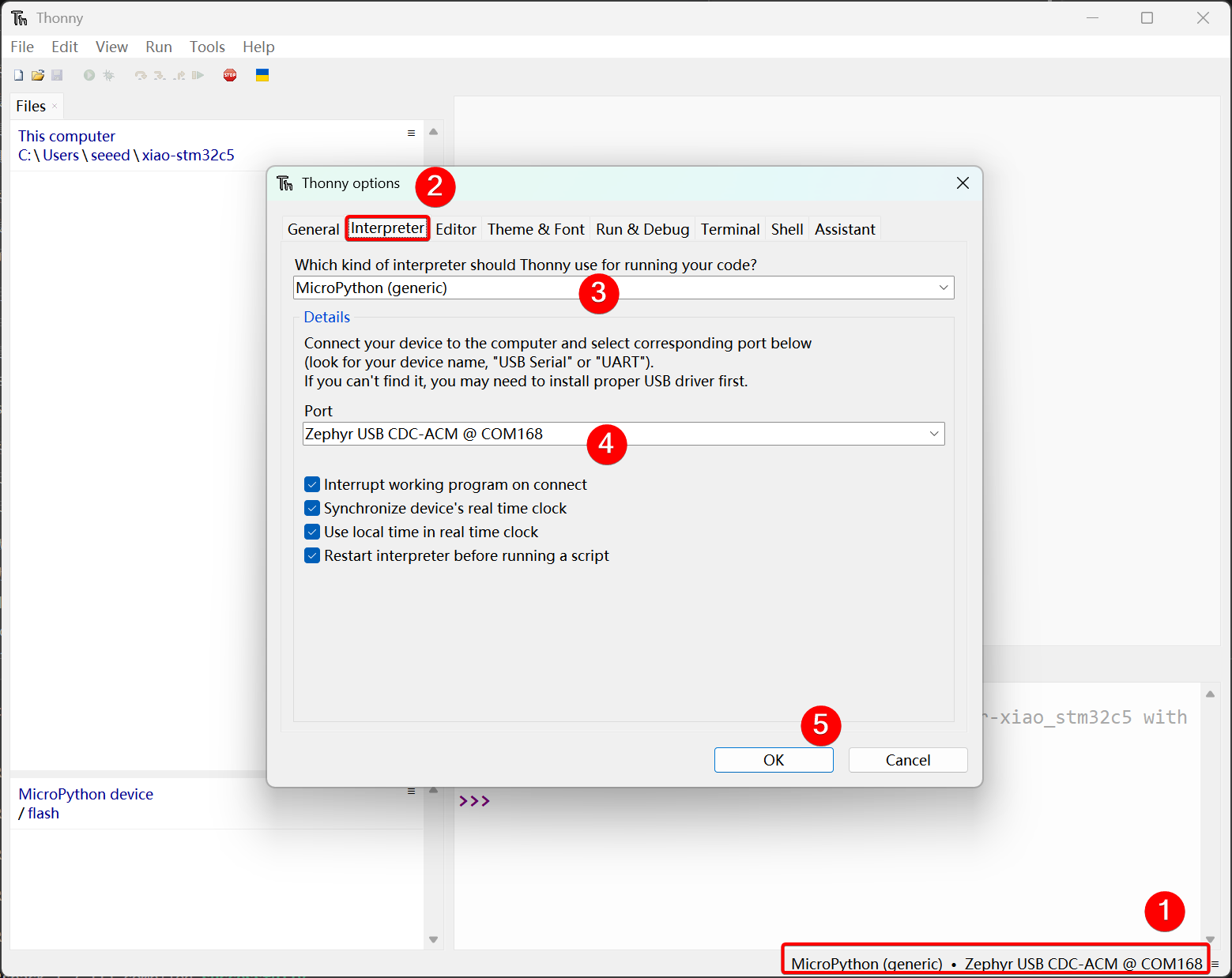
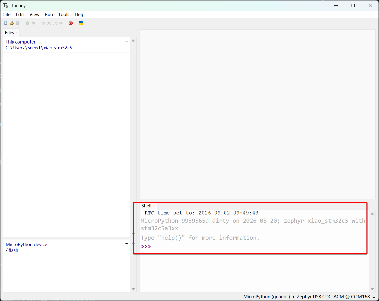
- After the firmware has been installed and Thonny has connected to the XIAO STM32C5, the MicroPython firmware information will appear in the Shell pane.
Pin Map
- For complete pinout details, see the XIAO STM32C5 Pin List.
| Pin / Signal | GPIO | Function | MicroPython Usage |
|---|---|---|---|
| D0 / A0 | PA0 | ADC1_IN0 / GPIO | XiaoADC(0) / XiaoPin(0) |
| D1 / A1 | PA1 | ADC1_IN1 / GPIO | XiaoADC(1) / XiaoPin(1) |
| D2 / A2 | PA2 | ADC1_IN2 / GPIO | XiaoADC(2) / XiaoPin(2) |
| D3 / A3 | PA3 | ADC1_IN3 / GPIO | XiaoADC(3) / XiaoPin(3) |
| D4 | PB7 | I2C1 SDA / GPIO | Header I2C data |
| D5 | PB6 | I2C1 SCL / GPIO | Header I2C clock |
| D6 | PA9 | USART1 TX / GPIO | UART transmit |
| D7 | PA10 | USART1 RX / GPIO | UART receive |
| D8 | PE2 | SPI3 SCK / GPIO | Hardware SPI clock |
| D9 | PB0 | SPI3 MISO / GPIO | Hardware SPI data input |
| D10 | PB15 | SPI3 MOSI / GPIO | Hardware SPI data output |
| D11 | PB8 | GPIO / FDCAN1 RX capable | FDCAN1 is not enabled in the current firmware |
| D12 | PB9 | GPIO / FDCAN1 TX capable | FDCAN1 is not enabled in the current firmware |
| D13 | PB5 | FDCAN2 RX / GPIO | XiaoCAN("can0", ...) |
| D14 | PB13 | FDCAN2 TX / GPIO | XiaoCAN("can0", ...) |
| D15 / CAN_STB | PB14 | CAN transceiver standby | Low: normal; high: standby |
| CAN_H | — | CAN FD differential bus high | Onboard CAN transceiver output; not a GPIO |
| CAN_L | — | CAN FD differential bus low | Onboard CAN transceiver output; not a GPIO |
| BAT_EN | PA15 | Battery measurement enable | XiaoPin("bat_en", Pin.OUT) |
| BAT_READ | PA4 | ADC1_IN4 | XiaoADC("vbat"); battery voltage is approximately ADC voltage × 2 |
| IMU_SDA | PB4 | I2C2 SDA | Onboard LSM6DS3TR-C data |
| IMU_SCL | PB3 | I2C2 SCL | Onboard LSM6DS3TR-C clock |
| IMU_INT | PC13 | IMU INT1 | XiaoPin("imu_int", Pin.IN) |
| IMU_HEATER_PWM | PA8 | TIM1_CH1 PWM | XiaoPWM(0) |
| USER_LED | PB12 | GPIO output | XiaoPin("led", Pin.OUT); active low |
LED Blink
Digital pins mainly realize on-off control of external sensors and actuators by outputting high and low logic levels. Combined with the Grove Base for XIAO expansion board and standard Grove peripheral modules, this section elaborates on the underlying driver logic and practical invocation methods of digital pins on XIAO STM32C5.
Hardware Preparation
| Seeed Studio XIAO STM32C5 | Seeed Studio Grove Base for XIAO | Grove - LED Pack |
|---|---|---|
|  |  |
Software Program
This example uses the XIAO STM32C5 D1 pin as a digital output to blink an external LED.
- In Thonny, select File > New to create a file, then enter the following code:
# Copyright (c) 2026 Seeed Technology Co., Ltd.
# SPDX-License-Identifier: Apache-2.0
#
# Blinky example for XIAO STM32C5 with TinyUF2 bootloader support.

import time
from machine import Pin
from boards.xiao import XiaoPin

SLEEP_TIME_MS = 1000
D1_PIN = 1

# D1 corresponds to PA1.
d1_gpio = XiaoPin(D1_PIN, Pin.OUT)

# Match GPIO_OUTPUT_ACTIVE in the Zephyr example.
led_state = True
d1_gpio.value(1)

try:
    while True:
        led_state = not led_state
        d1_gpio.value(1 if led_state else 0)

        print("LED state:", "ON" if led_state else "OFF")
        time.sleep_ms(SLEEP_TIME_MS)

except KeyboardInterrupt:
    # Turn the output off when the script is stopped.
    d1_gpio.value(0)
    print("Blinky stopped")
- Select Run > Run current script, or press F5.
Result
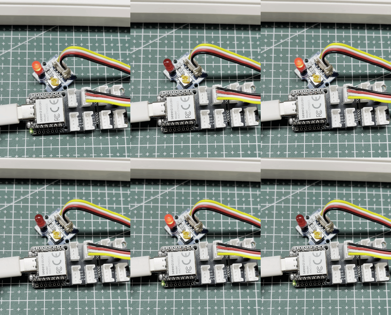
After the script starts, the external LED connected to D1 blinks at one-second intervals.
Drive a Servo Motor
PWM is a timing waveform output function implemented based on digital output GPIOs. It rapidly switches pin levels at a fixed frequency and dynamically adjusts the duty cycle of high level within a single cycle, so as to output equivalent analog signals to peripherals. In practical engineering applications, PWM is widely used for precise angle control of servo motors and smooth brightness adjustment of LEDs.
Hardware Preparation
| Seeed Studio XIAO STM32C5 | Seeed Studio Grove Base for XIAO | Grove - Servo |
|---|---|---|
| |  |
Software Program
This example uses D0 on the XIAO STM32C5 as the servo control-signal pin. The timing is generated in software rather than by a hardware PWM peripheral.
- In Thonny, select File > New to create a file, then enter the following code:
import time
from machine import Pin
from boards.xiao import XiaoPin

SERVO_PIN = 0                  # D0 / PA0
SERVO_PERIOD_US = 20_000       # 50 Hz
SERVO_MIN_US = 1_000           # Approximately 0 degrees
SERVO_MAX_US = 2_000           # Approximately 180 degrees

servo = XiaoPin(SERVO_PIN, Pin.OUT)
servo.value(0)


def output_servo_frame(angle):
    """Output one 20 ms servo-control frame."""
    angle = max(0, min(180, angle))

    pulse_us = SERVO_MIN_US + (
        angle * (SERVO_MAX_US - SERVO_MIN_US) // 180
    )

    frame_start = time.ticks_us()

    servo.value(1)
    time.sleep_us(pulse_us)
    servo.value(0)

    elapsed = time.ticks_diff(time.ticks_us(), frame_start)
    remaining = SERVO_PERIOD_US - elapsed

    if remaining > 0:
        time.sleep_us(remaining)


def hold_angle(angle, duration_ms):
    """Keep the servo at an angle for the specified duration."""
    frames = max(1, duration_ms // 20)

    for _ in range(frames):
        output_servo_frame(angle)


try:
    print("Software servo control started on D0")

    hold_angle(90, 1000)

    while True:
        for angle in range(0, 181):
            output_servo_frame(angle)

        for angle in range(180, -1, -1):
            output_servo_frame(angle)

except KeyboardInterrupt:
    print("Servo control stopped")

finally:
    servo.value(0)
- Select Run > Run current script, or press F5.
Result
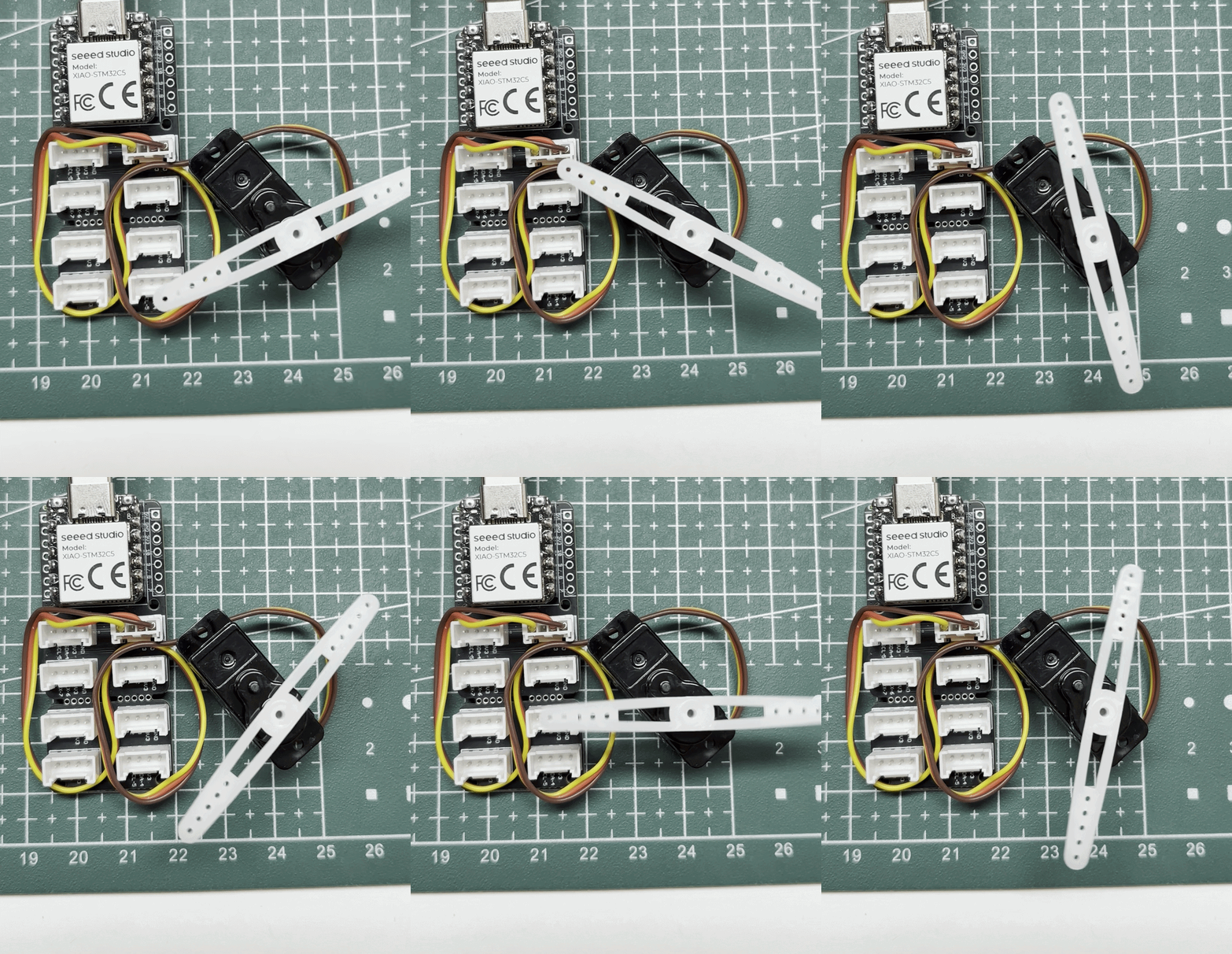
After the script starts, the servo repeatedly sweeps from approximately 0° to 180° and back to 0°. The loop advances the command by 1° per 20 ms control frame, corresponding to a nominal command sweep rate of 50°/s (approximately 0.87 rad/s), excluding execution overhead and the servo's own mechanical limits.
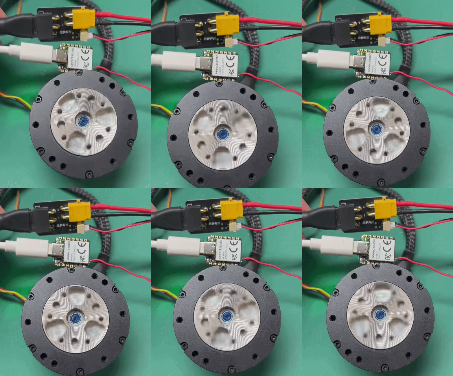
Drive a DM-J4310-2EC Motor over CAN
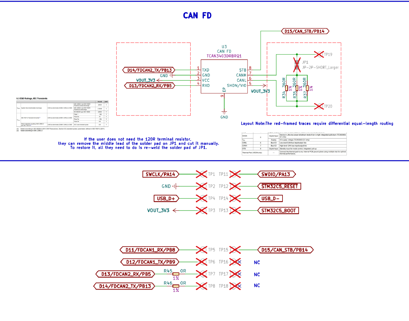
The XIAO STM32C5 provides two CAN FD interfaces. One exposes logic-level transmit and receive signals for use with an external CAN transceiver. The other is connected to the onboard TCAN3403-Q1 CAN FD transceiver and can connect directly to a CAN bus through CAN_H and CAN_L. CAN FD remains compatible with Classical CAN while supporting a larger payload and a higher data-phase bit rate, making it suitable for automotive electronics, industrial control, robotics, and distributed sensor networks.
The onboard CAN FD circuit also includes a disconnectable 120 Ω termination resistor. Enable this resistor when the board is at one end of the bus. Disconnect it when the board is in the middle of the bus or when another 120 Ω resistor is already installed at the XIAO end of the bus. The transceiver also supports standby control for reduced power consumption when CAN communication is not in use.
- Reference Usage: XIAO STM32C5 CANFD Usage
Hardware Preparation
- XIAO STM32C5 × 1
- Computer and USB Type-C data cable
- Regulated 24 V DC power supply suitable for the motor
- DM-J4310-2EC motor × 1
- XT30 2+2 Power Separation Board
| Seeed Studio XIAO STM32C5 | DM4310 | XT30 2+2 Power Separation Board |
|---|---|---|
|  |  |
Software Program
The motor requires a 24 V supply. Use a compliant, current-limited power supply with an appropriate current rating. Switch off the supply before changing any wiring, keep the motor unloaded during initial testing, and connect the XIAO ground to the motor power-supply negative terminal. Incorrect power or wiring can damage the equipment and create a safety hazard.
- Use the Damiao host-computer configuration software to set the motor's CAN ID to
0x001and Master ID to0x011. For details, see Getting Started with the Damiao 43 Series Motors.
- Connect the motor to the XIAO STM32C5's rear CAN_H and CAN_L pads. The onboard transceiver uses D13/PB5 (RX), D14/PB13 (TX), and D15/PB14 (standby); drive D15 low for normal operation.
- In Thonny, select File > New to create a file, then save the following program as
driver_dm4310.py:
driver_dm4310.py
"""Drive a Damiao DM-J4310-2EC V1.1 from XIAO STM32C5.
This motor example uses Classical CAN at 1 Mbit/s (fd=False), although the board supports CAN FD.
Protocol: classic CAN 2.0B at 1 Mbit/s, Damiao speed mode.

Wiring:
    XIAO CAN_H -> motor CAN_H
    XIAO CAN_L -> motor CAN_L
    XIAO GND   -> motor GND / 24 V negative
    Motor VCC  -> external 24 V positive

Use 120-ohm termination at both ends of the CAN bus. Never connect the
MCU-side CAN TX/RX pins directly to the motor.
"""

import struct
import time
from machine import Pin
from boards.xiao import XiaoCAN, XiaoPin


# Motor and CAN configuration.
DM_MOTOR_ID = 0x001
DM_MASTER_ID = 0x011
DM_CAN_BITRATE = 1_000_000

DM_CONTROL_ID = 0x200 + DM_MOTOR_ID
DM_PARAM_ID = 0x7FF

DM_CMD_ENABLE = 0xFC
DM_CMD_DISABLE = 0xFD
DM_CMD_CLEAR_ERROR = 0xFB

DM_PARAM_WRITE = 0x55
DM_REG_CTRL_MODE = 0x0A
DM_CTRL_MODE_SPEED = 3

DM_VMAX_RAD_S = 30.0

CONTROL_PERIOD_MS = 20
GEAR_PERIOD_MS = 5_000
FEEDBACK_PRINT_MS = 500
START_DELAY_MS = 3_000

# Same speed sequence as the Zephyr example.
SPEED_SEQUENCE = (0.0, 3.0, 6.0, 10.0, 6.0, 3.0)


def send_control(can, command):
    payload = bytes((0xFF, 0xFF, 0xFF, 0xFF,
                     0xFF, 0xFF, 0xFF, command))
    can.send(DM_CONTROL_ID, payload)


def write_u32_parameter(can, register, value):
    payload = struct.pack(
        "<HBBI",
        DM_MOTOR_ID,
        DM_PARAM_WRITE,
        register,
        value,
    )
    can.send(DM_PARAM_ID, payload)


def send_speed(can, speed_rad_s):
    can.send(DM_CONTROL_ID, struct.pack("<f", float(speed_rad_s)))


def decode_feedback(frame):
    """Return decoded Damiao feedback, or None for an unrelated frame."""
    if frame is None or len(frame) < 2:
        return None

    can_id = frame[0]
    data = frame[1]

    if data is None or len(data) < 8:
        return None

    motor_id = data[0] & 0x0F
    if motor_id != (DM_MOTOR_ID & 0x0F):
        return None

    fault = data[0] >> 4
    position_raw = (data[1] << 8) | data[2]
    velocity_raw = (data[3] << 4) | (data[4] >> 4)
    torque_raw = ((data[4] & 0x0F) << 8) | data[5]

    velocity_rad_s = (
        (velocity_raw / 4095.0) * 2.0 - 1.0
    ) * DM_VMAX_RAD_S

    return {
        "can_id": can_id,
        "motor_id": motor_id,
        "fault": fault,
        "position_raw": position_raw,
        "velocity_raw": velocity_raw,
        "velocity_rad_s": velocity_rad_s,
        "torque_raw": torque_raw,
        "mos_temperature": data[6],
        "rotor_temperature": data[7],
    }


def print_feedback(feedback):
    print(
        "FB id=0x{:03X} motor={} err=0x{:X} pos=0x{:04X} "
        "vel=0x{:03X} {:.2f}rad/s tq=0x{:03X} mos={}C rotor={}C".format(
            feedback["can_id"],
            feedback["motor_id"],
            feedback["fault"],
            feedback["position_raw"],
            feedback["velocity_raw"],
            feedback["velocity_rad_s"],
            feedback["torque_raw"],
            feedback["mos_temperature"],
            feedback["rotor_temperature"],
        )
    )


def drain_feedback(can, duration_ms, print_frames=False):
    deadline = time.ticks_add(time.ticks_ms(), duration_ms)

    while time.ticks_diff(deadline, time.ticks_ms()) > 0:
        frame = can.recv(0)
        if frame is None:
            time.sleep_ms(5)
            continue

        feedback = decode_feedback(frame)
        if print_frames and feedback is not None:
            print_feedback(feedback)


def initialise_motor(can):
    # Clear error -> select speed mode -> enable.
    send_control(can, DM_CMD_CLEAR_ERROR)
    drain_feedback(can, 100)

    write_u32_parameter(can, DM_REG_CTRL_MODE, DM_CTRL_MODE_SPEED)
    drain_feedback(can, 100)

    send_control(can, DM_CMD_ENABLE)
    drain_feedback(can, 100)


def stop_motor(can):
    """Best-effort controlled stop followed by motor disable."""
    if can is None:
        return

    try:
        # Repeat zero speed briefly so the motor receives the stop request.
        for _ in range(5):
            send_speed(can, 0.0)
            time.sleep_ms(CONTROL_PERIOD_MS)
        send_control(can, DM_CMD_DISABLE)
        time.sleep_ms(50)
    except Exception as exc:
        print("Motor stop warning:", exc)


def main():
    can = None
    can_stb = None

    try:
        print("XIAO STM32C5 DM-J4310-2EC speed-mode driver")
        print(
            "motor_id=0x{:03X} master_id=0x{:03X} bitrate={}Mbps".format(
                DM_MOTOR_ID,
                DM_MASTER_ID,
                DM_CAN_BITRATE // 1_000_000,
            )
        )

        # PB14 / D15 is active-high standby. Drive it low for normal mode.
        can_stb = XiaoPin(15, Pin.OUT)
        can_stb.value(0)
        time.sleep_ms(10)

        can = XiaoCAN(
            "can0",
            bitrate=DM_CAN_BITRATE,
            data_bitrate=2_000_000,
            fd=False,
            loopback=False,
        )

        print("Check wiring and keep the motor unloaded.")
        print("Starting in {} seconds...".format(START_DELAY_MS // 1000))
        time.sleep_ms(START_DELAY_MS)

        initialise_motor(can)
        print("Motor enabled in speed mode")

        sequence_index = 0
        speed = SPEED_SEQUENCE[sequence_index]
        print("Target speed: {:.2f} rad/s".format(speed))

        next_gear = time.ticks_add(time.ticks_ms(), GEAR_PERIOD_MS)
        last_feedback_print = time.ticks_ms()

        while True:
            now = time.ticks_ms()

            if time.ticks_diff(now, next_gear) >= 0:
                sequence_index = (sequence_index + 1) % len(SPEED_SEQUENCE)
                speed = SPEED_SEQUENCE[sequence_index]
                print("Target speed: {:.2f} rad/s".format(speed))
                next_gear = time.ticks_add(next_gear, GEAR_PERIOD_MS)

            send_speed(can, speed)

            # Drain every queued frame so the MicroPython CAN queue cannot fill.
            while True:
                frame = can.recv(0)
                if frame is None:
                    break

                feedback = decode_feedback(frame)
                if feedback is None:
                    continue

                if time.ticks_diff(now, last_feedback_print) >= FEEDBACK_PRINT_MS:
                    print_feedback(feedback)
                    last_feedback_print = now

            time.sleep_ms(CONTROL_PERIOD_MS)

    except KeyboardInterrupt:
        print("User requested stop")
    except Exception as exc:
        print("Motor driver error:", exc)
        raise
    finally:
        stop_motor(can)

        if can is not None:
            try:
                can.deinit()
            except Exception:
                pass

        if can_stb is not None:
            try:
                can_stb.value(1)
            except Exception:
                pass

        print("Motor disabled; CAN transceiver in standby")


if __name__ == "__main__":
    main()
- Select Run > Run current script, or press F5.
Result
After the motor is enabled, the DM-J4310 cycles through target speeds of 0 → 3 → 6 → 10 → 6 → 3 rad/s, changing the target every five seconds. The Shell displays the selected target speed and decoded motor-feedback data. The example does not control the onboard LED.
Connect CAN_H on the XIAO STM32C5 to CAN_H on the motor, and CAN_L to CAN_L. Also connect the grounds. Reversing the differential lines or omitting the common ground can prevent communication.
Tech Support & Product Discussion
Thank you for choosing our products! We are here to provide you with different support to ensure that your experience with our products is as smooth as possible. We offer several communication channels to cater to different preferences and needs.