XIAO STM32C5 With STM32CubeIDE
Overview
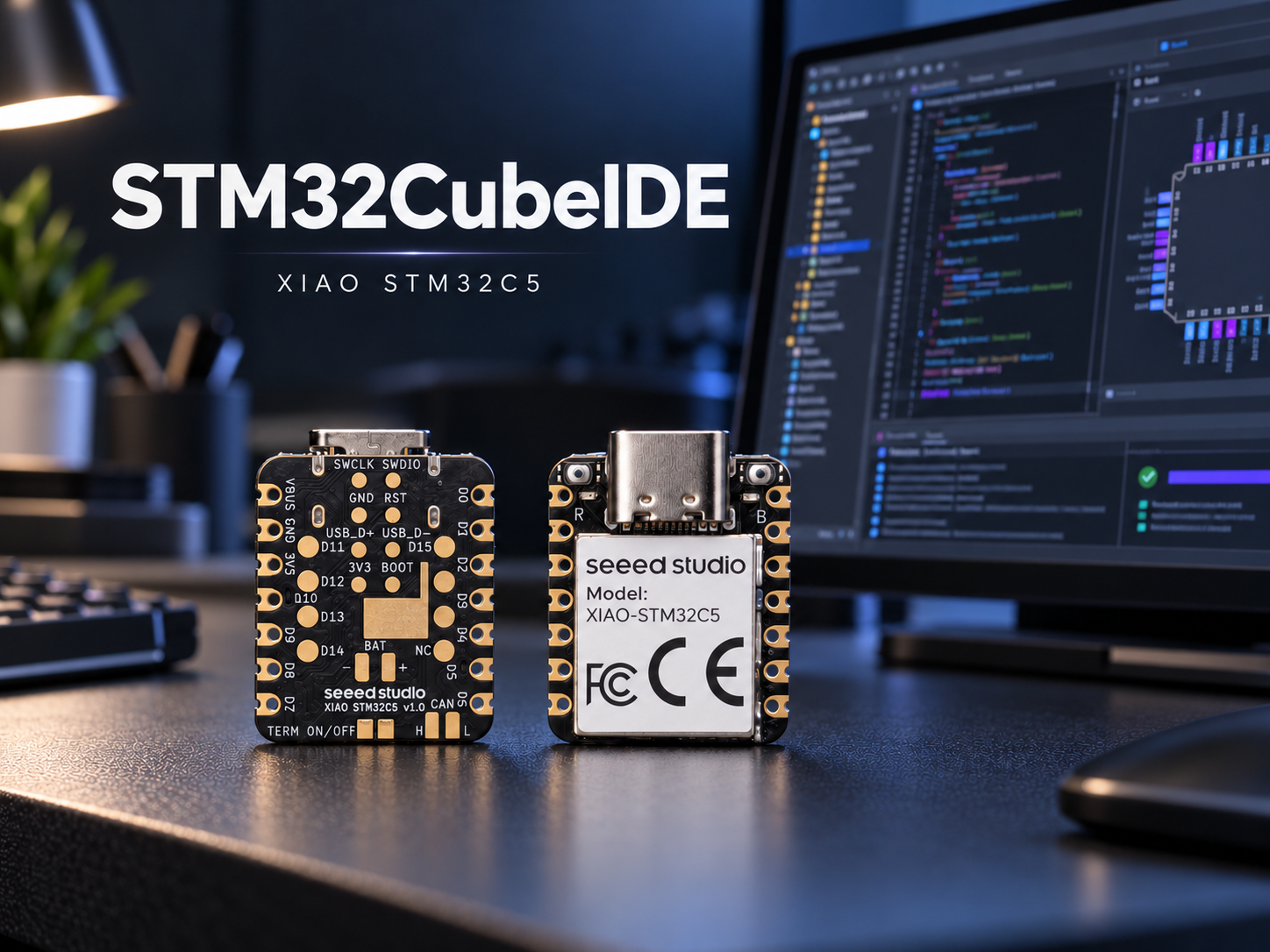
STM32CubeIDE is STMicroelectronics’ official free, cross-platform integrated development environment for STM32 microcontrollers. It is also suitable for developing applications for the XIAO STM32C5.
STM32CubeIDE provides the GNU Arm toolchain and supports CMake- and Ninja-based build workflows, reducing the need for additional environment configuration. It covers the complete development workflow, including project creation, peripheral configuration, code editing, compilation, firmware programming, and on-target debugging.
Hardware Preparation
Before getting started, prepare the following items:
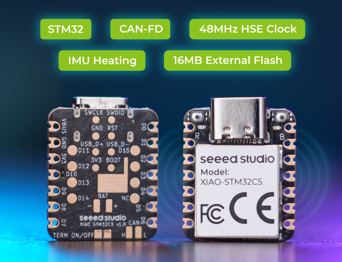
- 1 × XIAO STM32C5
- PC and Type‑C USB cable
- 1 × ST‑LINK/V2 (optional)
| Seeed Studio XIAO STM32C5 |
|---|
 |
Installing STM32CubeIDE
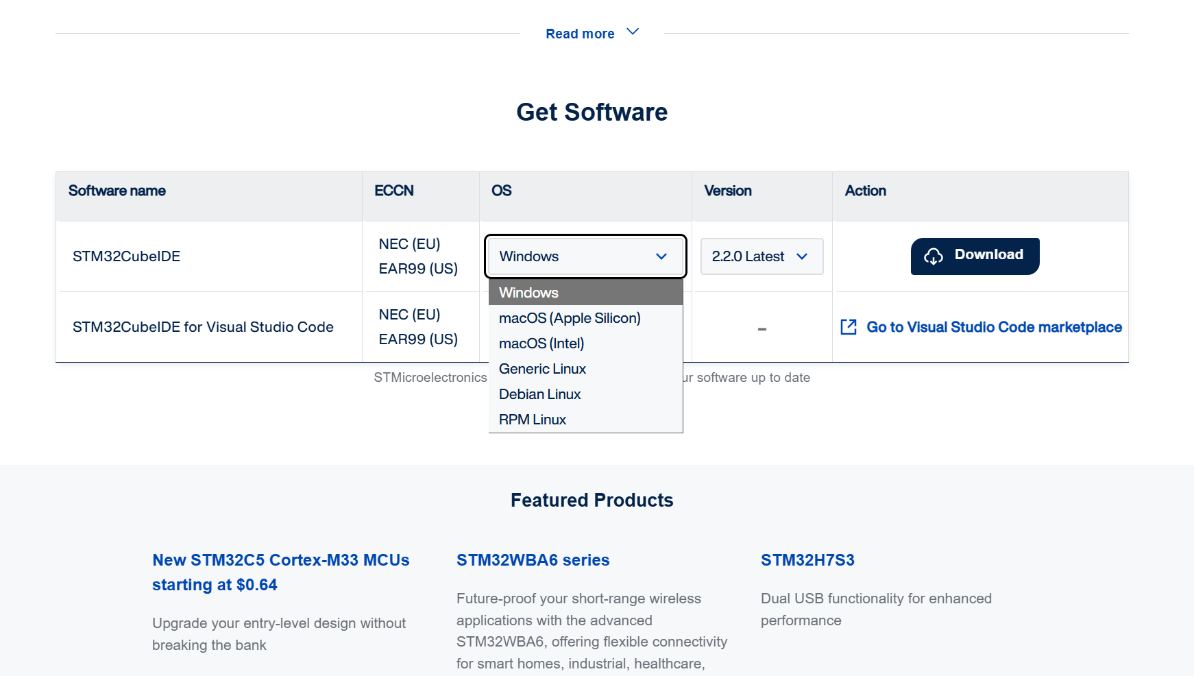
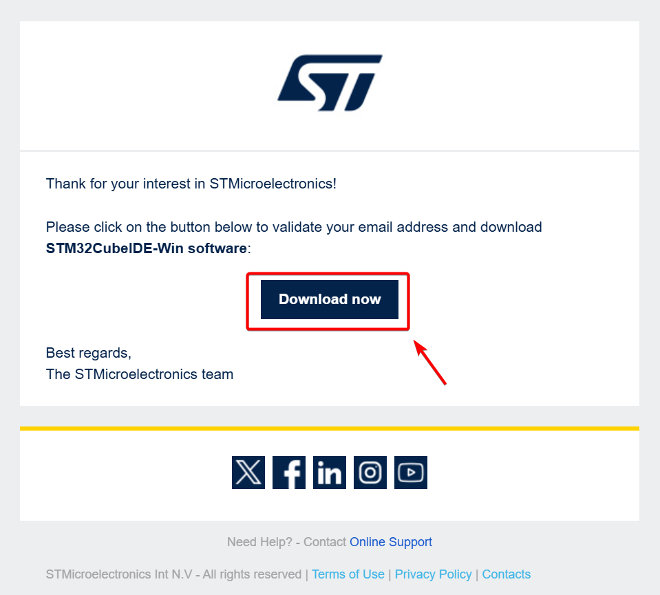
- Download the installation package. Click STM32CubeIDE Software to navigate to the download page. Select Get Software on the homepage, or scroll down to the bottom of the page. Choose the installer matching your PC operating system. It is recommended to use the latest version.
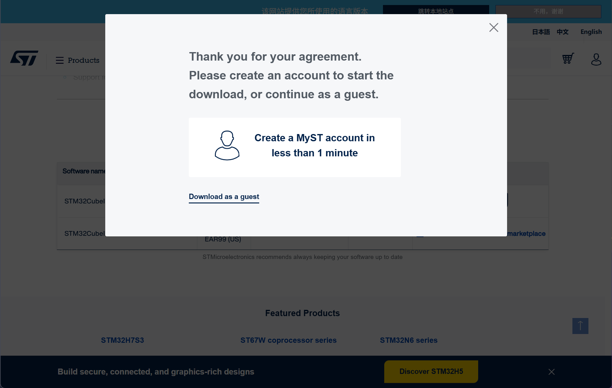
- You may download the installer either with a registered account or as a guest. Email and other related information are required for this process.
- The download link will be sent to your email address. Click the link to obtain the software installer.
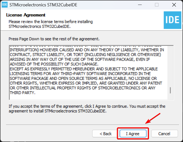
- Launch the installer, read the relevant license agreements, then select I Agree.
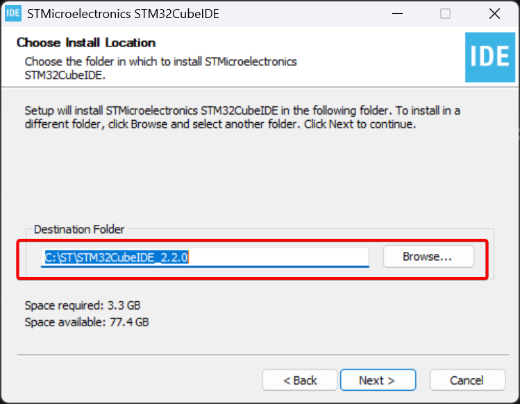
- Select the installation directory.
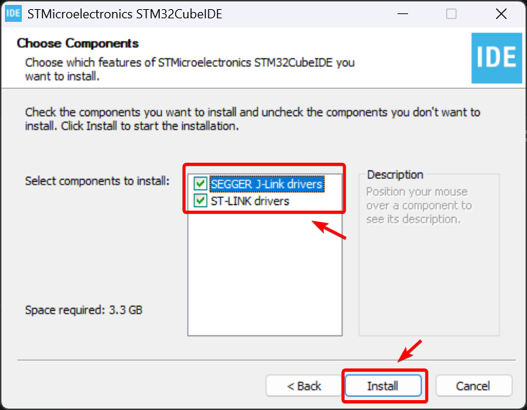
- Install the driver for the debug probe you plan to use. Probe drivers are not required for the UF2 flashing steps below.
Developing with XIAO STM32C5
- Since the XIAO STM32C5 natively supports flashing UF2‑format firmware, a reference example project is provided to simplify your development. Click the link below to download the example:
-
🗃️[Project] XIAO STM32C5 Blink Project
-
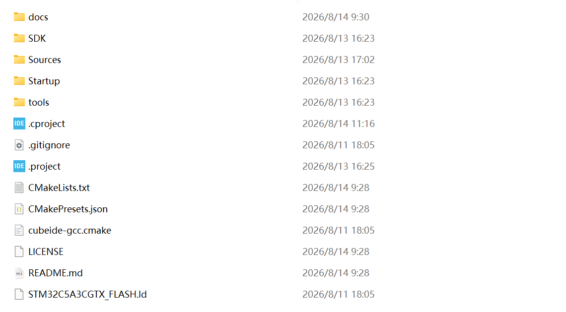
Extract the archive after downloading. The resulting project structure should match the layout shown below.
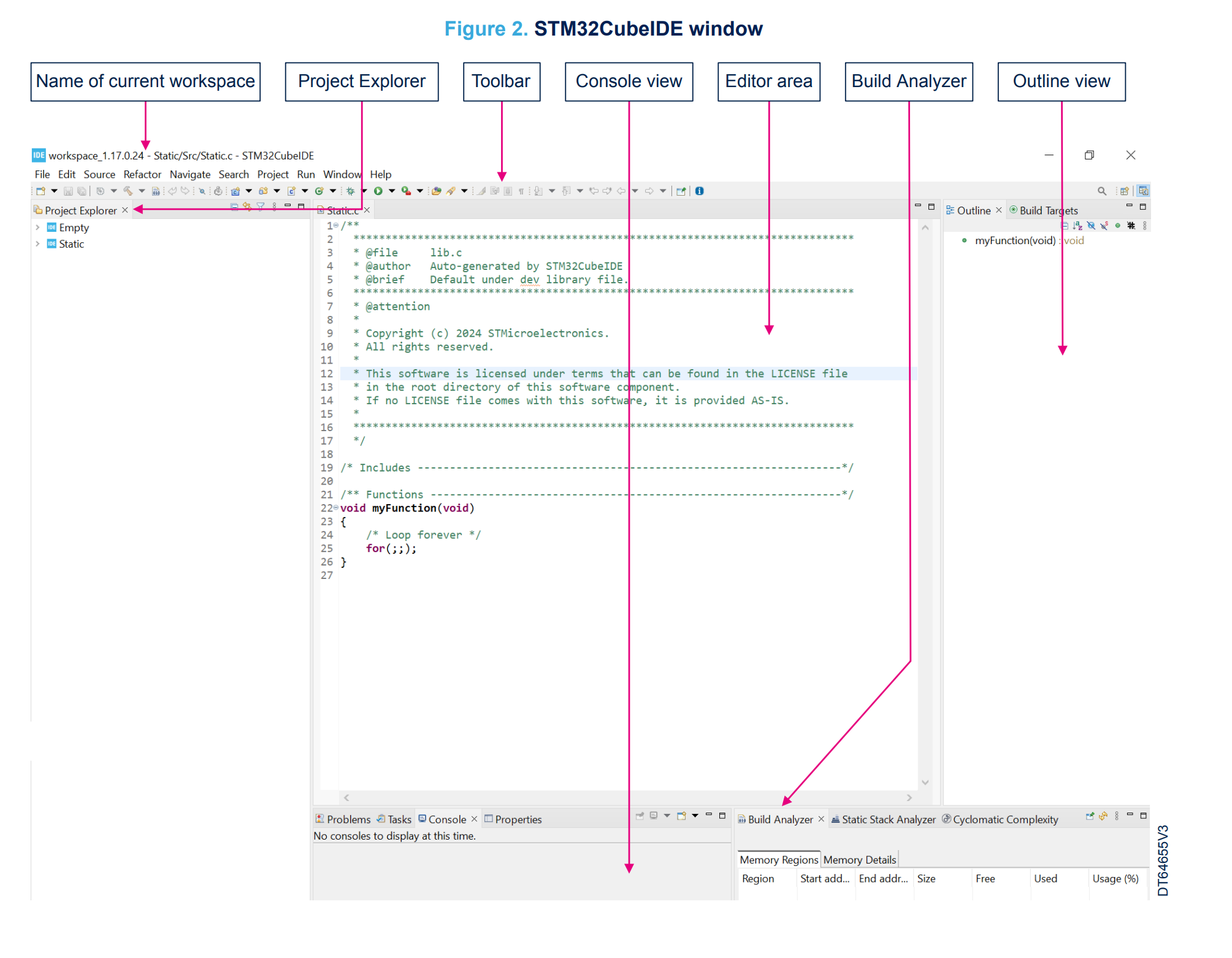
- Launch STM32CubeIDE; the interface shown below will appear. Content in this section is excerpted from 📄[PDF] STM32CubeIDE User Guide
On first startup, STM32CubeIDE asks for workspace selection. The default workspace works fine and will not affect later steps.
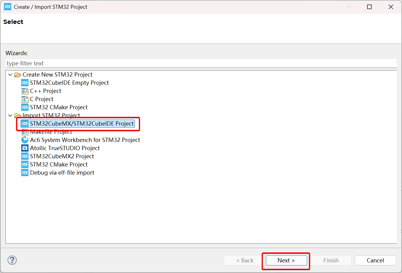
- Import the project. On the upper‑right toolbar, navigate to File → STM32 Project Create/Import, then select Import STM32CubeMX / STM32CubeIDE Project.
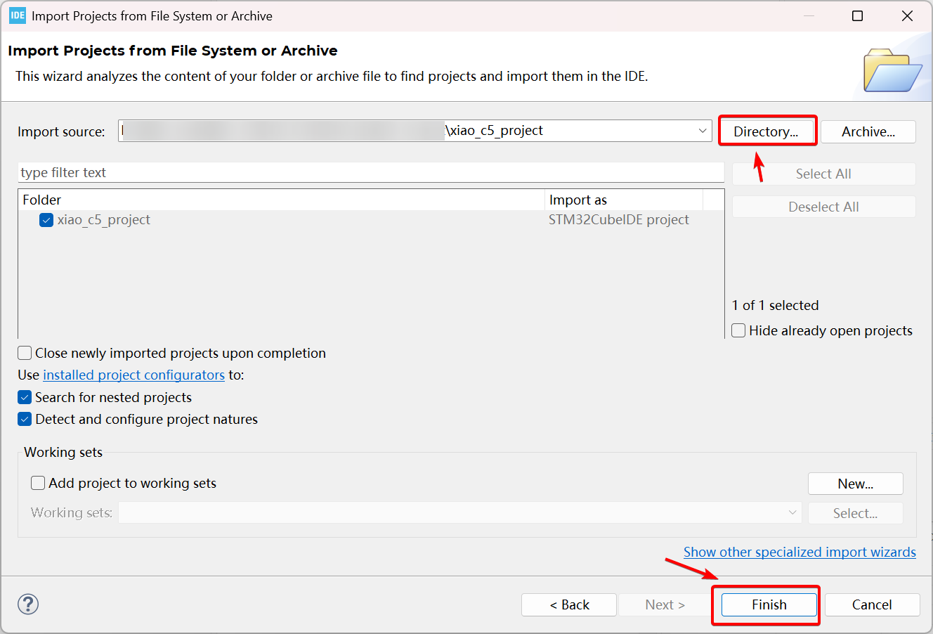
- Pick the extracted xiao_c5_project project directory and click Finish.
- After import, the project structure is shown in the figure below.
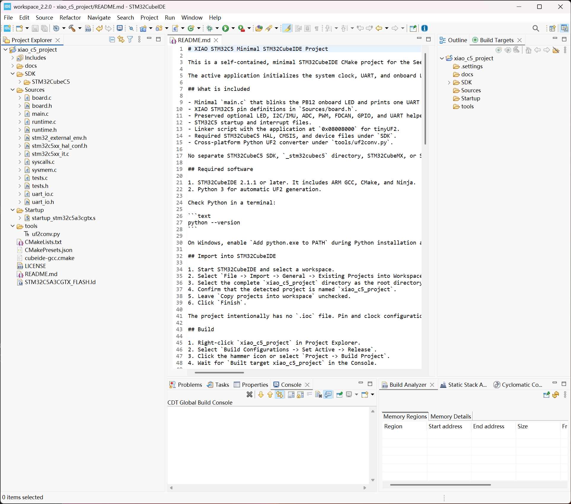
- SDK: Contains the STM32CubeC5 SDK package. This is a trimmed‑down SDK that only includes files essential for building XIAO STM32C5 firmware; it is not the full SDK release.
- Source: Source code directory, holding
main.cand board‑specific definition files for the XIAO STM32C5. - Startup: Mandatory startup files for the XIAO STM32C5.
- tools: Contains the
uf2conv.pyscript, which converts compiled bin binaries into UF2 format after each build.
Building and Flashing Firmware
- Program overview. Open Source → main.c. This is a simple on‑board LED blink example for the XIAO STM32C5. It toggles the LED logic level every 500 ms to achieve the blinking effect.
/**
 * @file    main.c
 * @brief   Minimal LED application for the Seeed XIAO STM32C5.
 *
 * SPDX-License-Identifier: MIT
 * Copyright (c) 2026 Seeed Technology Co., Ltd.
 */
#include "board.h"
#include "uart_io.h"

int main(void)
{
    if (HAL_Init() != HAL_OK) {
        Error_Handler();
    }

    board_clock_init();
    board_uart_init();
    board_led_init();

//    uprintln("[LED] PB12 onboard LED is blinking (500 ms interval)");
    uart_log_flush();

    while (1) {
        HAL_GPIO_TogglePin(LED_PORT, LED);
        uprintln("[LED] PB12 onboard LED is blinking");
        uart_log_flush();
        HAL_Delay(500U);
    }
}
board_clock_init();: Initializes the peripheral clocks required for XIAO STM32C5.board_uart_init();: Initializes UART I/O configuration for XIAO STM32C5.board_led_init();: Initializes I/O configuration for the on‑board user LED of XIAO STM32C5.HAL_GPIO_TogglePin(LED_PORT, LED);: STM32 HAL library GPIO toggle function, which toggles the GPIO logic level of the user LED.
- On the toolbar, select Release to trigger automatic project building.
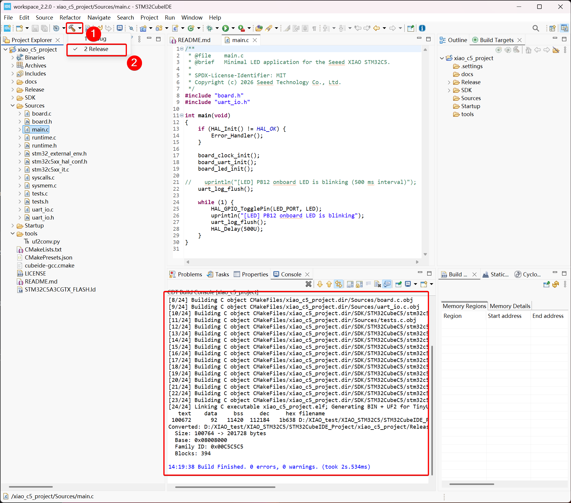
- After a successful build, a Release folder will be generated containing multiple build artifacts. Among these outputs, the bin file and uf2 file are the files you need.
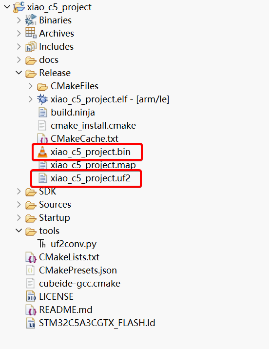
You may also Build the project by selecting Build. This creates a Build folder which contains the generated firmware files.
Flashing UF2‑Format Firmware
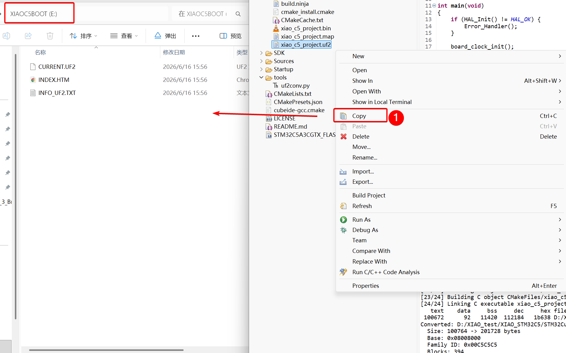
- Double‑tap the reset button on the XIAO STM32C5. The XIAO STM32C5 mass‑storage drive will pop up. Copy the UF2 file onto this drive to finish flashing.
Flashing with ST-LINK/V2
ST-LINK/V2 is an official debugging and programming tool released by STMicroelectronics. It supports STM8 and STM32 microcontroller families, and enables program downloading, firmware flashing and on‑chip debugging via SWIM, JTAG or SWD interfaces. The following section describes how to flash firmware to the XIAO STM32C5 using ST‑LINK/V2 together with STM32CubeIDE
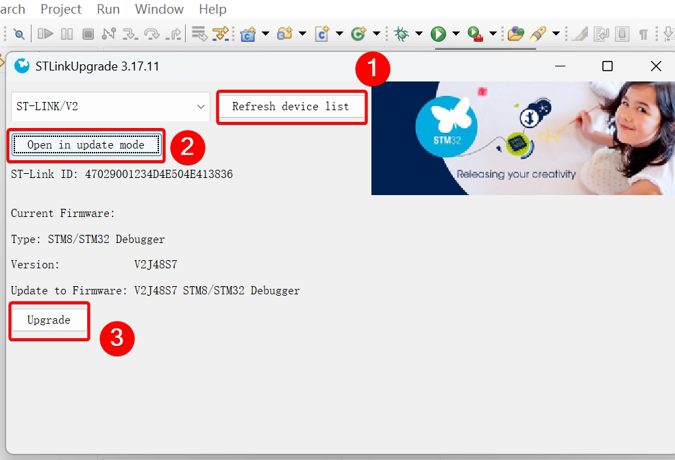
- Connect the ST‑LINK/V2 to your PC. In the IDE, go to Help → ST‑LINK Upgrade and update its firmware to the latest version to guarantee good compatibility with STM32C5 devices.
- Connect the ST‑LINK/V2 to the XIAO STM32C5. See below for pin connections. Soldering is required for this step.
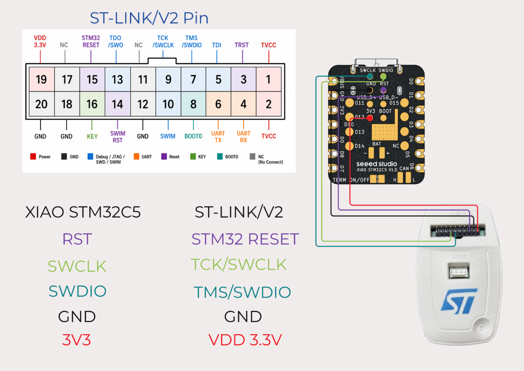
- Among the connection pins, RST is an optional interface and may be left unconnected.
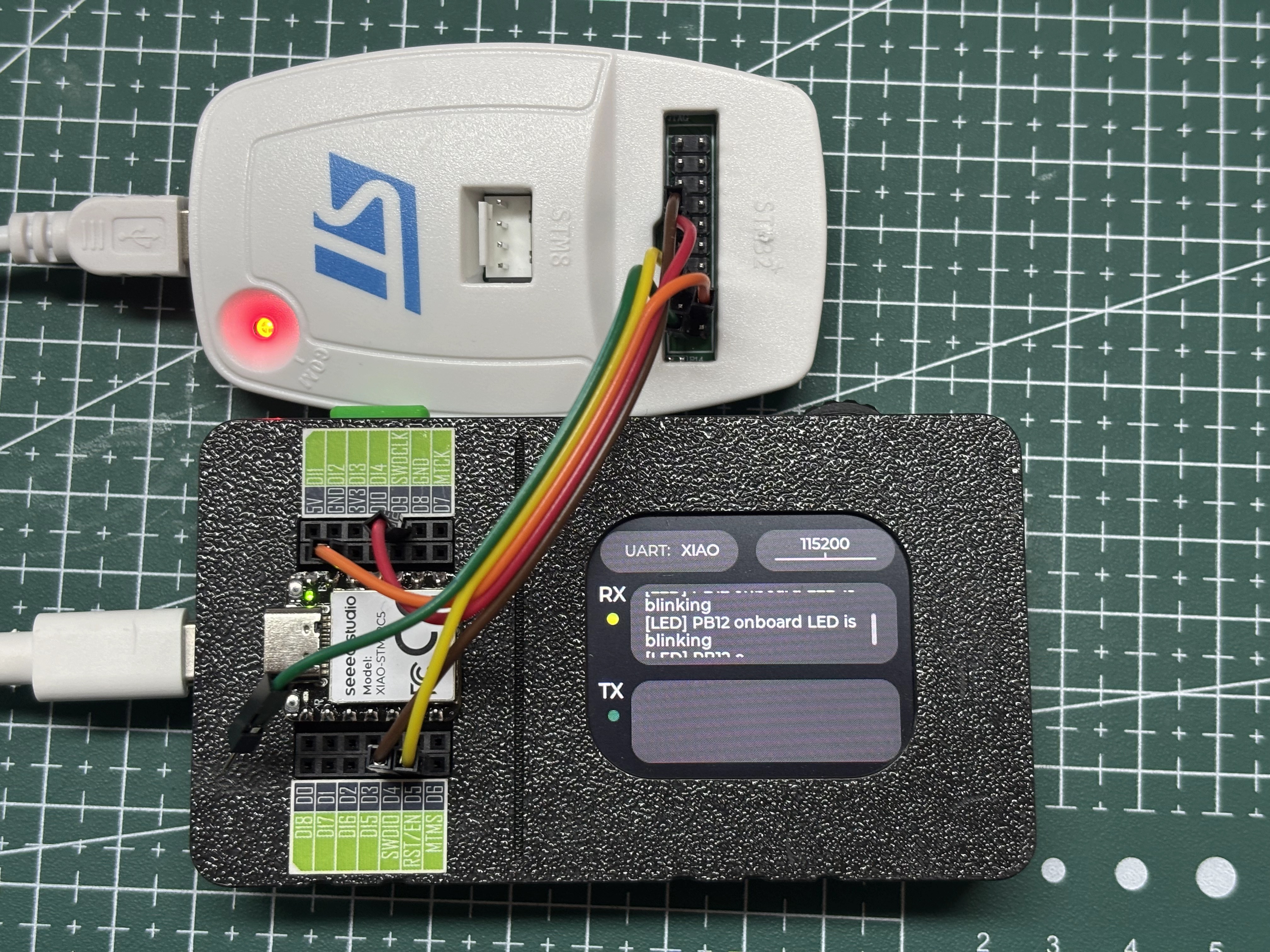
- You may also use the XIAO Debug Mate to connect to the ST‑LINK/V2 tool, which eliminates manual soldering.
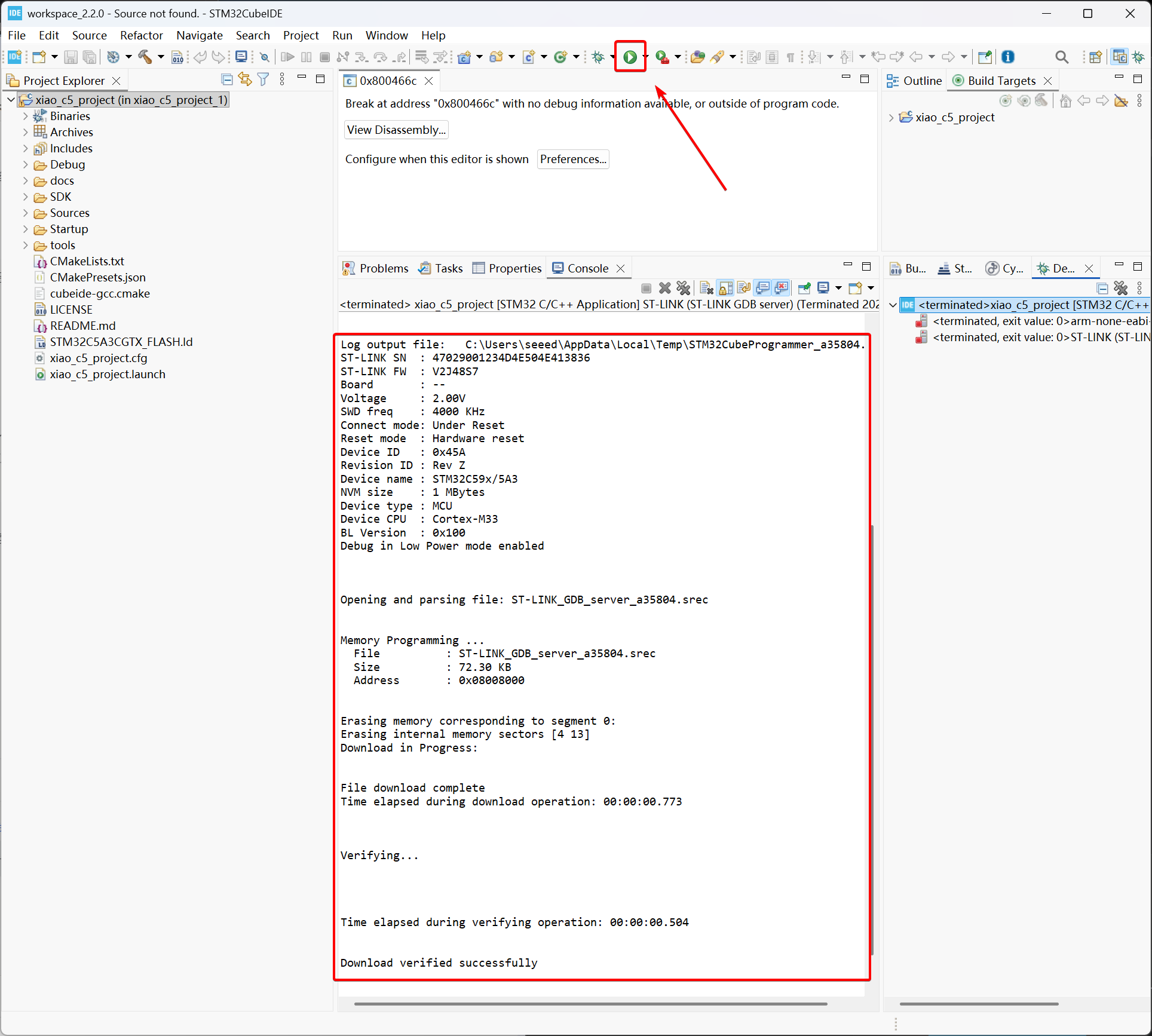
- Click Run on the toolbar to complete flashing. STM32CubeIDE will automatically detect the ST‑LINK/V2 programmer.
Summary
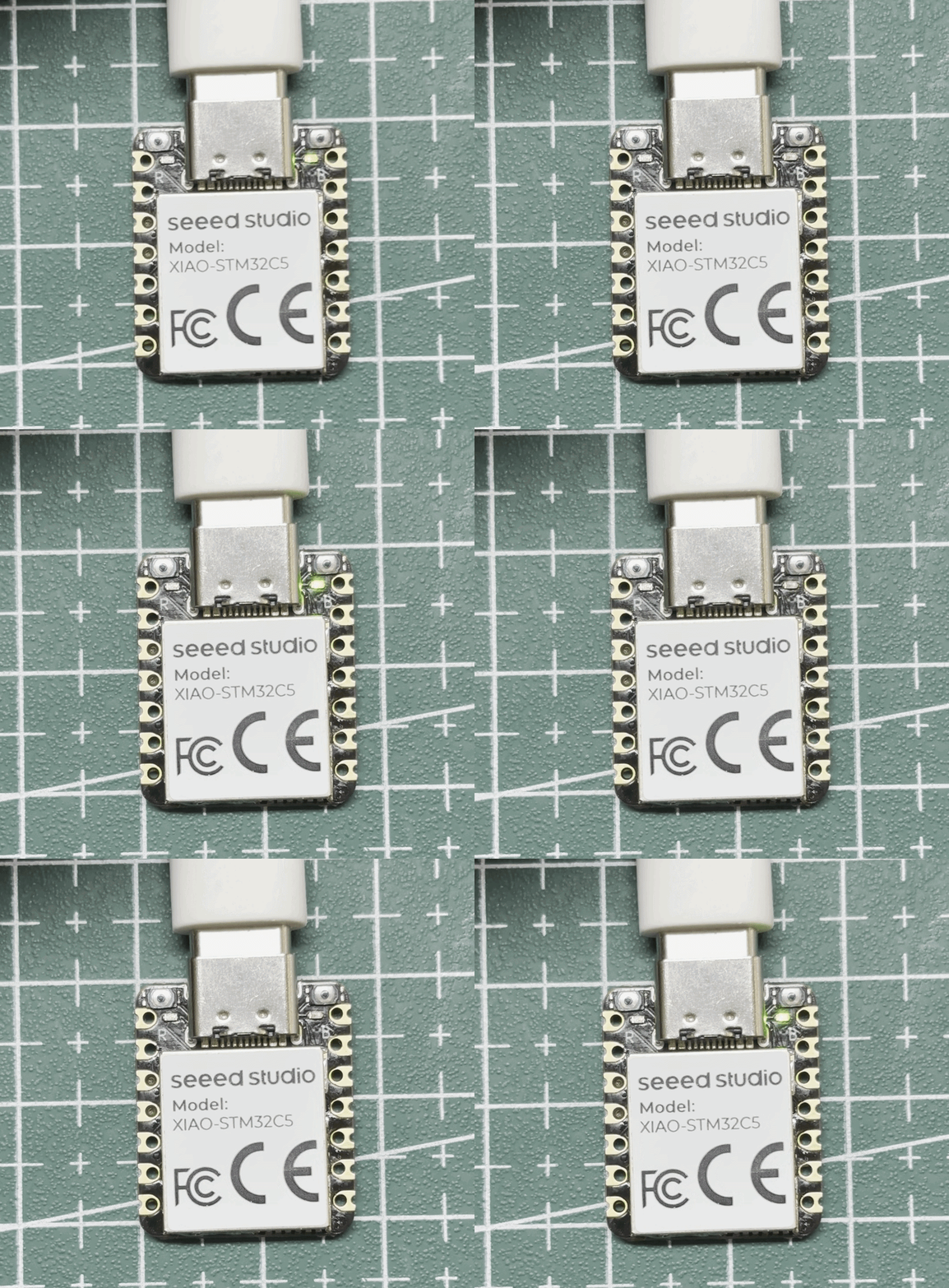
- After flashing the corresponding firmware to the XIAO STM32C5 using the methods above, the on‑board user LED will toggle and blink every 500 ms.
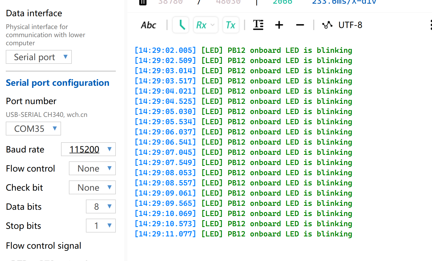
You may also connect D6 and D7 to a TTL‑to‑UART adapter. Open any serial monitor; the serial port will print the string [LED] PB12 onboard LED is blinking every 500 ms.
Files inside the Source Folder
-
board.c / board.h
Defines pin mapping and board‑specific resources for XIAO STM32C5. It provides initialization configurations for peripherals including clock, GPIO, CAN and ADC, and can serve as the foundation for application development.
-
test.c / test.h
Provides verification routines for on‑board peripherals such as IMU and LED, as well as interfaces including CAN, SPI, I2C and ADC. These routines can be used for hardware function validation and code reference.
-
uart_io.c / uart_io.h
Handles character processing and command parsing for received UART data, offering an interactive entry point for test routines. Low‑level communication interfaces are implemented by other modules.
Reference Resources
- 🗃️[Project] XIAO STM32C5 Blink Project
- 📄[Document] STM32CubeIDE User Guide
- 📄[Datasheet] STM32C5A3CGX
- 📄[Examples] STM32 Example Library
Tech Support & Product Discussion
Thank you for choosing our products! We are here to provide you with different support to ensure that your experience with our products is as smooth as possible. We offer several communication channels to cater to different preferences and needs.