Getting Started with reServer Industrial
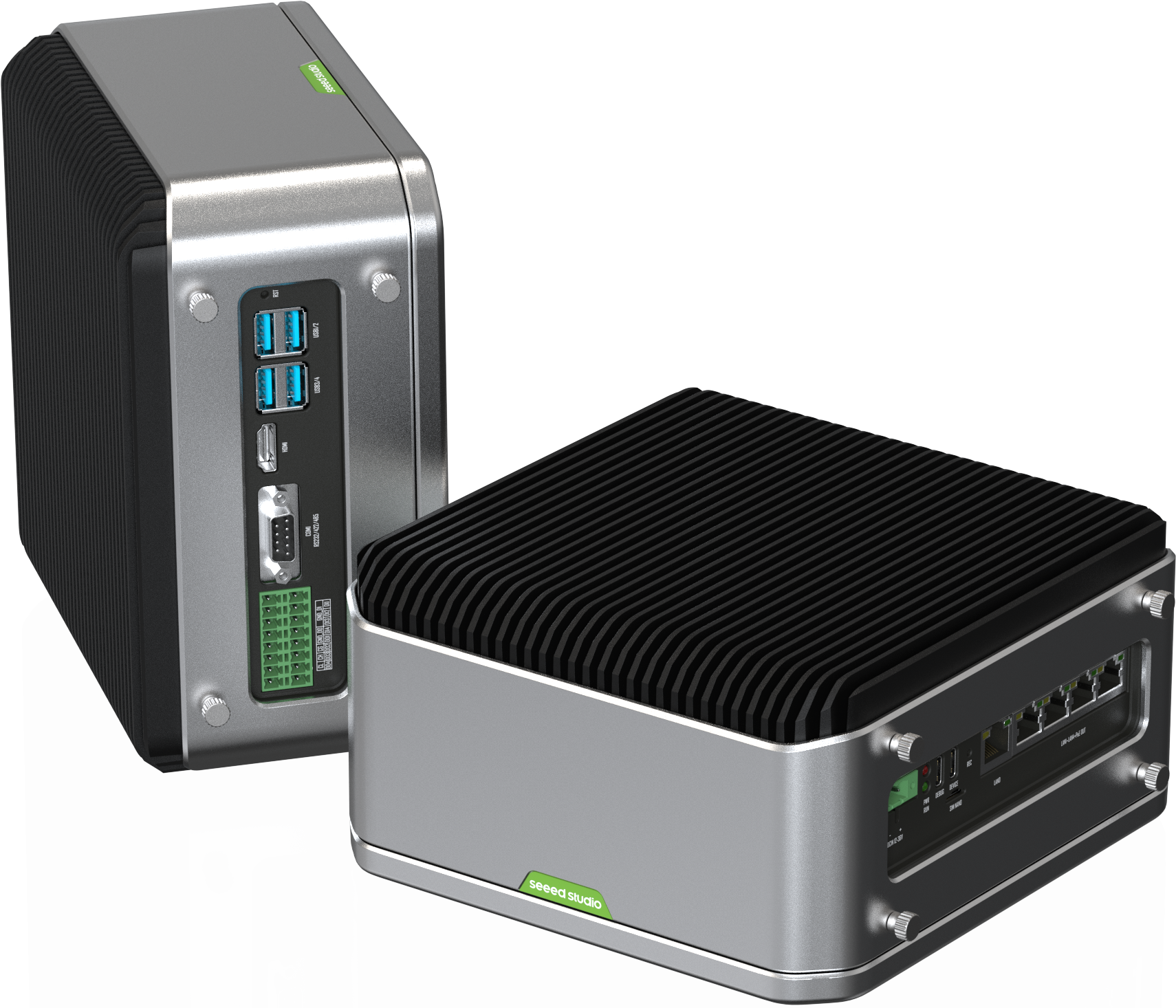
reServer Industrial series offers fanless, compact, AI-enabled NVR (Network Video Recorder) servers including NVIDIA Jetson™ Orin Nano/Orin NX modules, ranging from 20 TOPS to 100 TOPS AI performance. reServer Industrial is preinstalled with Jetpack 5.1.1, simplifies development, ideal for bulding VMS (Video Management System) together with powerful AI capabilities, which brings digital transformantion across industries of smart cities, security, industrial automation, smart factories.
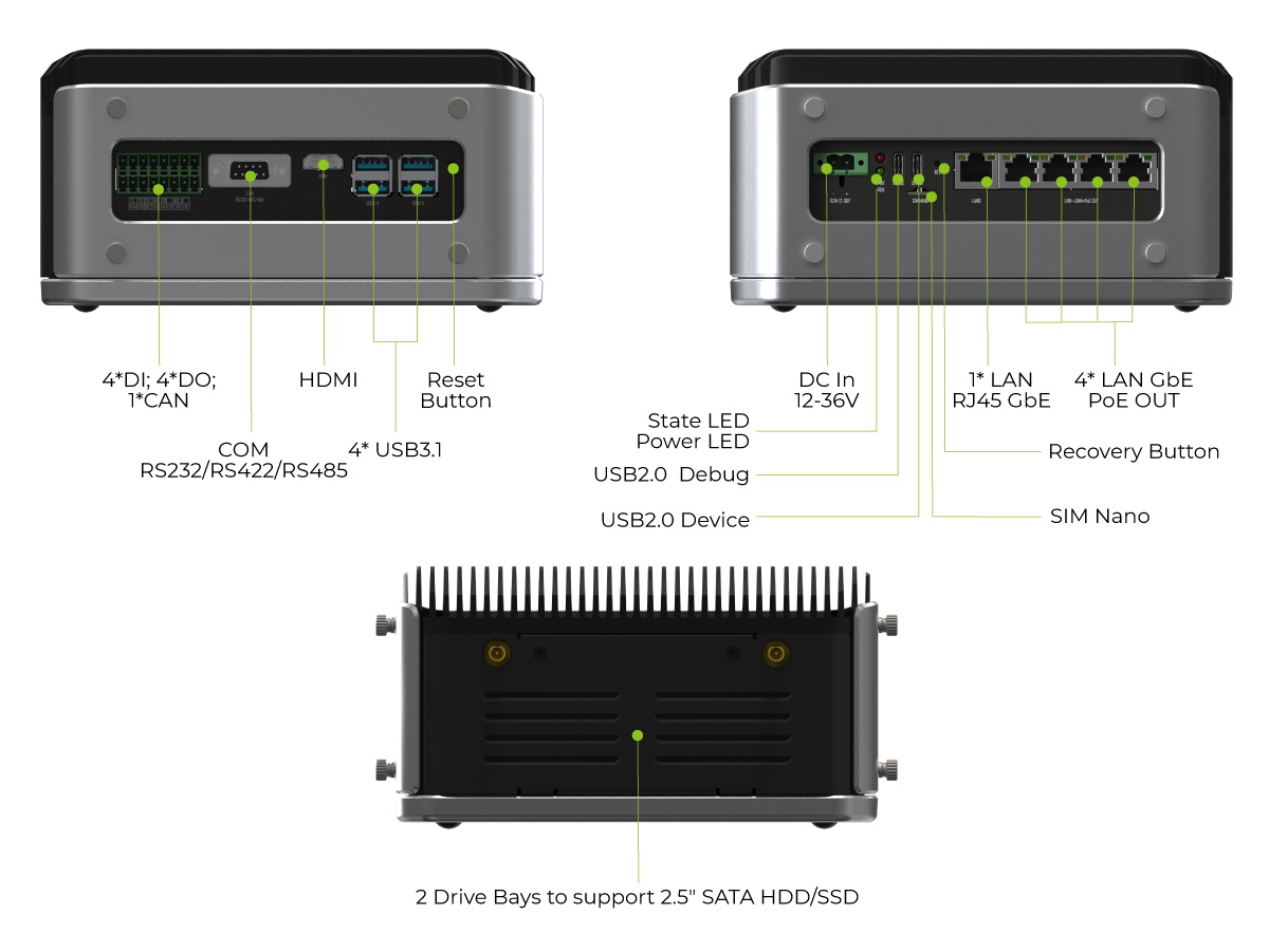
reServer Industrial features 2x 2.5" SATA HDD/ SSD drive bays to easily store hundreds of local video footages in a video analytics application. Also it enables multiple connectivity options including 5 RJ-45 Ethernet ports, 1 RS232/422/485, 4x Isolated DI/DO, 1x CAN, 4* USB3.1. Fanless design with versatile mounting options allows deployment from -20 to 60 ℃, which is ideal for more harsh environments and heavier loads.
reServer Industrial comes with a passive heatsink and a fanless design, making it ideal for use in demanding environments. The passive heatsink allows for efficient cooling without the need for a fan, reducing the risk of component failure due to dust or other contaminants. The fanless design also reduces noise levels and power consumption, making it suitable for use in noise-sensitive environments and minimizing energy costs.
reServer industrial has 5 RJ45 GbE ports, 4 of which are PoE PSE ports for providing power over Ethernet to devices like IP cameras. This eliminates the need for a separate power source and makes it easier to deploy network devices in areas without readily available power outlets. The remaining GbE port is used to connect to a network switch or router, enabling communication with other devices on the network and access to the Internet.
Features
- Fanless Compact Edge AI Server: Powered by NVIDIA Jetson™ Orin Nano/Orin NX modules, ranging from 20 TOPS to 100 TOPS AI performance, wider temperature range from -20 ~ 60°C with 0.7m/s airflow
- Multi-Stream Processing: 5* GbE RJ45(4 for 802.3af PSE ), handles multiple streams with real-time processing
- Expandable Storage: 2 drive bays for 2.5" SATA HDD/SSD, plus an M.2 2280 socket for NVMe SSD
- Industrial Interfaces: Includes COM port, DI/DO ports, CAN port, USB 3.1, and optional TPM2.0 module
- Hybrid Connectivity: Supports 5G/4G/LTE/LoRaWAN® (module optional) with Nano SIM card slot
- Certifications: FCC, CE, UKCA, ROHS, KC
Specifications
| Product Name | reServer Industrial J4012 | reServer Industrial J4011 | reServer Industrial J3011 | reServer Industrial J3010 | |
|---|---|---|---|---|---|
| NVIDIA Jetson Module | Orin NX 16GB | Orin NX 8GB | Orin Nano 8GB | Orin Nano 4GB | |
| SKU | 114110247 | 114110248 | 114110249 | 114110250 | |
| Processor System | AI Performance | 100 TOPS | 70 TOPS | 40 TOPS | 20 TOPS |
| GPU | 1024-core NVIDIA Ampere architecture GPU with 32 Tensor Cores | 512-core NVIDIA Ampere architecture GPU with 16 Tensor Cores | |||
| CPU | 8-core Arm® Cortex®-A78AE v8.2 64- bit CPU; 2MB L2 + 4MB L3 | 6-core Arm® Cortex®-A78AE v8.2 64-bit CPU 1.5MB L2 + 4MB L3 | |||
| Memory | 16GB 128-bit LPDDR5 102.4GB/s | 8GB 128-bit LPDDR5 102.4GB/s | 8GB 128-bit LPDDR5 68 GB/s | 4GB 64-bit LPDDR5 34 GB/s | |
| Video Encode | Standards supported: H.265 (HEVC), H.264, AV1 1*4K60 (H.265) | 3*4K30 (H.265) | 6*1080p60 (H.265) | 12*1080p30 (H.265) | 1080p30 supported by 1-2 CPU cores | |||
| Video Decode | Standards supported: H.265 (HEVC), H.264, VP9, AV1 1*8K30 (H.265) | 2*4K60 (H.265) | 4*4K30 (H.265) | 9*1080p60 (H.265) | 18*1080p30 (H.265) | Standards supported: H.265 (HEVC), H.264, VP9, AV1 1*4K60 (H.265) | 2*4K30 (H.265) | 5*1080p60 (H.265) | 11*1080p30 (H.265) | |||
| Storage | eMMC | - | |||
| Expansion | M.2 Key M (2280) PCIe Gen4.0 SSD (M.2 NVMe SSD 128G included) | ||||
| I/O | Ethernet | 1* LAN0 RJ45 GbE (10/100/1000Mbps) | |||
| 4* LAN RJ45 GbE PoE(PSE 802.3 af 15 W, 10/100/1000Mbps) | |||||
| USB | 4* USB3.1, 1* USB2.0 Type C(Device mode), 1* USB2.0 Type C For Debug UART & RP2040 | ||||
| DI/DO | 4*DI,4*DO,3*GND_DI,2*GND_DO,1*GND_ISO,1*CAN | ||||
| COM | 1* DB9 (RS232/RS422/RS485) | ||||
| Display | 1*HDMI 2.1 Type A 7680x4320 at 30 Hz | 1*HDMI 1.4 Type A 3840x2160 at 30 Hz | |||
| SATA | 2 Drive Bays to support 2.5" SATA HDD/SSD(SATA III 6.0Gbps) | ||||
| SIM | 1* Nano SIM card slot | ||||
| Button | Reset Button, Recovery Button | ||||
| Expansion | Mini PCIe | Mini PCIe for LoRaWAN®/4G/Series Wireless (Module optional) | |||
| M.2 Key B | M.2 Key B (3042/3052) support 4G/5G (Module optional) | ||||
| Fan | Fanless, passive heatsink; 1*Fan connectors(5V PWM) | ||||
| TPM | 1* TPM 2.0 connector (Module optional) | ||||
| RTC | 1* RTC socket (CR1220 included),*RTC 2-pin | ||||
| Power | Power Supply | DC 12V-36V Terminal block 2 pin | |||
| Power Adapter | 24V /5A Power Adapter(Without power cord) | ||||
| Mechanical | Dimensions (W x D x H) | 194.33mm*187mm*95.5mm | |||
| Weight | 2.8kg | ||||
| Installation | Desk, DIN rail, VESA | ||||
| Operating Temperature | -20 ~ 60°C with 0.7m/s | ||||
| Operating Humidity | 95% @ 40 °C (Non-condensing) | ||||
| Storage temperature | -40 ~ 85°C | ||||
| Storage humidity | 60°C@ 95% RH(Non-condensing) | ||||
| Vibration | 3 Grms @ 5 ~ 500 Hz, random, 1 hr/axis | ||||
| Shock | 50G peak acceleration (11 msec. duration,eMMC,microSD, or mSATA) | ||||
| OS | Pre-installed Jetpack 5.1.1 (above) (provide Linux OS with board support package) | ||||
| Certification | FCC, CE, RoHS, UKCA, KC | ||||
| Warranty | 2 Years | ||||
Hardware Overview
Full System
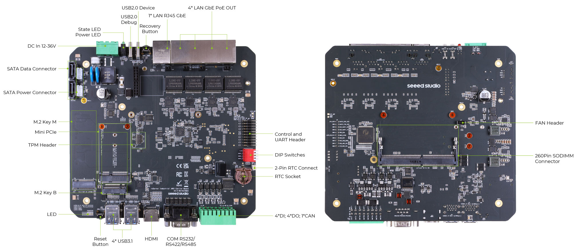
Carrier Board
Flash JetPack
reServer Industrial comes pre-installed with JetPack 5.1.1 on a 128GB SSD along with the necessary drivers. This includes SDK components such as CUDA, CUDNN and TensorRT. However, if you want to reflash Jetpack to the included SSD or to a new SSD, you can follow the steps below. Currently we only provide guidance for JP5.1.1 and we will keep updating this in the future.
Prerequisites
You need to prepare the following hardware before getting started with reServer Industrial
- reServer Industrial
- Provided Power Adapter with power cord (US version or EU version)
- Ubuntu Host PC (native or VM using VMware Workstation Player)
- USB Type-C data transmission cable
- External monitor
- HDMI cable
- Keyboard and Mouse
Enter Force Recovery Mode
Now you need to enter recovery mode on the reServer Industrial board in order to flash the device. Connect a USB Type-C cable between DEVICE port and your PC. Use a pin and insert into the REC hole to press the recovery button and while holding this, connect the included 2-Pin Terminal block power connector to the power connector on the board (make sure to use the 2 screws to screw the terminal in place) and connect the included power adapter with a power cord to turn on the board
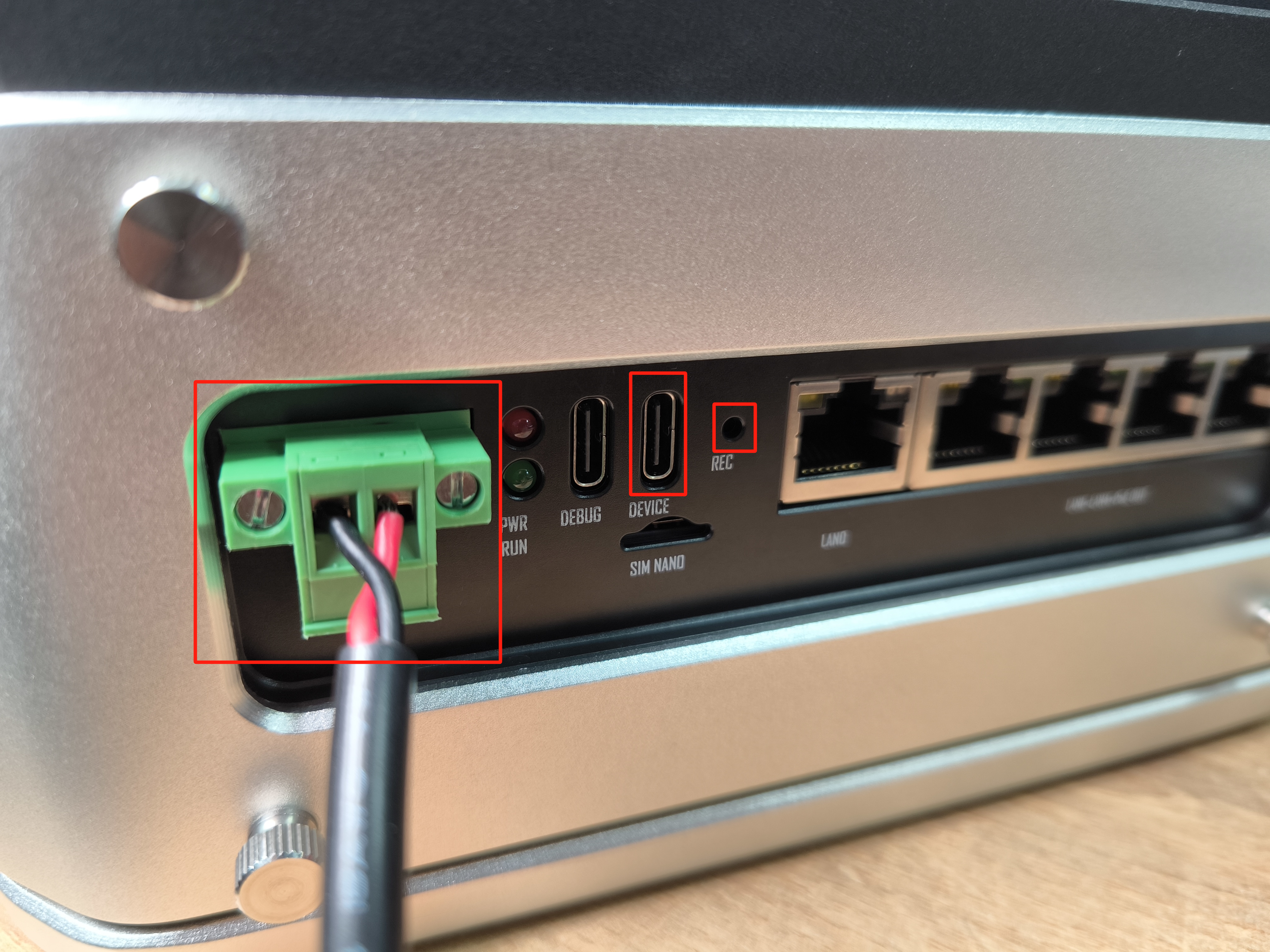
Make sure you power on the device while holding the RECOVERY button or otherwise it will not enter recovery mode
On the Ubuntu host PC, open a Terminal window and enter the command lsusb. If the returned content has one of the following outputs according to the Jetson SoM you use, then the board is in force recovery mode.
- For Orin NX 16GB: 0955:7323 NVidia Corp
- For Orin NX 8GB: 0955:7423 NVidia Corp
- For Orin Nano 8GB: 0955:7523 NVidia Corp
- For Orin Nano 4GB: 0955:7623 NVidia Corp
Different Methods of Flashing
Here we offer 2 different methods of flashing.
- Download the entire system image we have prepared which includes NVIDIA JetPack, hardware periheral drivers and flash to device
- Download official NVIDIA L4T, use the included hardware periheral drivers and flash to device
The first method download is around 14GB and the second method download is about 3GB
- Method 1
- Method 2
Download System Image
- Step 1: Download the system image to your Ubuntu PC corresponding to the board you are using
| Device | Image Link | JetPack Version | L4T Version |
|---|---|---|---|
| reServer Industrial J4012 | Download | 5.1.1 | 35.3.1 |
| reServer Industrial J4011 | Download | ||
| reServer Industrial J3011 | Download | ||
| reServer Industrial J3010 | Download |
The source code for the above images can be found here
- Step 2: Extract the generated file
tar -xvf <file_name>.tar.gz
Flash to Jetson
- Step 1: Navigate to the extracted file from before and execute the flash command as follows
cd mfi_reserver-orin-industrial
sudo ./tools/kernel_flash/l4t_initrd_flash.sh --flash-only --massflash 1 --network usb0 --showlogs
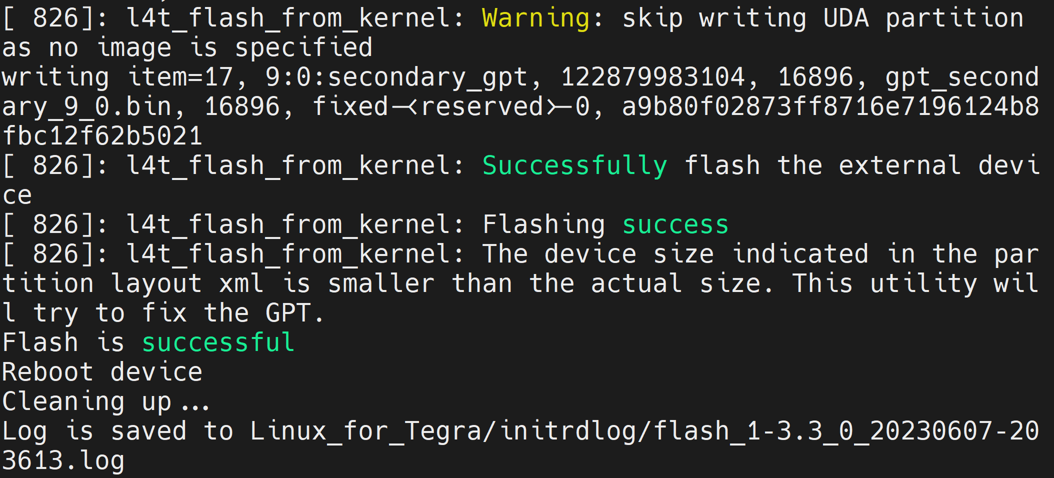
Now it will start to flash the system image to the board. If the flashing is successful, you will see the below output
- Step 2: Connect the board to a display using the HDMI connector on the board and finish the initial configuration setup
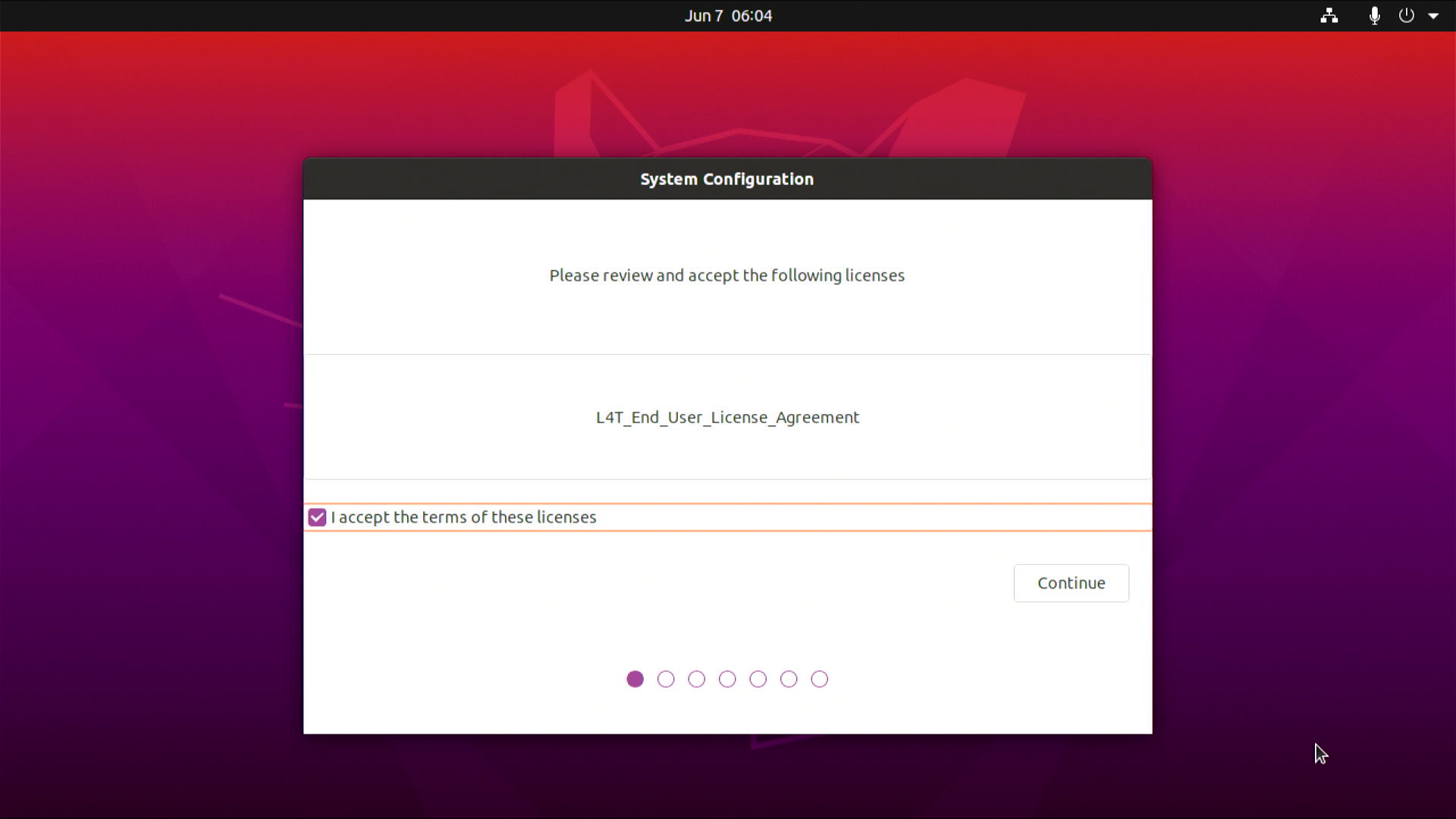
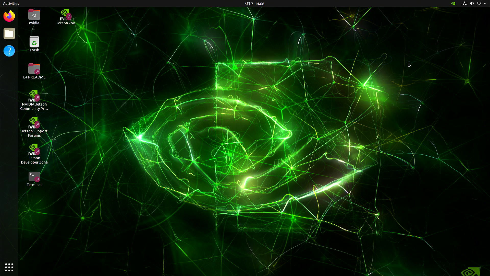
After that, the board will reboot and will be ready to use!
Download and Prepare NVIDIA L4T and rootfs
wget https://developer.nvidia.com/downloads/embedded/l4t/r35_release_v3.1/release/jetson_linux_r35.3.1_aarch64.tbz2
wget https://developer.nvidia.com/downloads/embedded/l4t/r35_release_v3.1/release/tegra_linux_sample-root-filesystem_r35.3.1_aarch64.tbz2
tar xf jetson_linux_r35.3.1_aarch64.tbz2
sudo tar xpf tegra_linux_sample-root-filesystem_r35.3.1_aarch64.tbz2 -C Linux_for_Tegra/rootfs/
cd Linux_for_Tegra/
sudo ./apply_binaries.sh
sudo ./tools/l4t_flash_prerequisites.sh
Download and Prepare Drivers
- Step 1: Download the driver files to your Ubuntu PC corresponding to the board you are using
| Jetson Module | Download Link | JetPack Version | L4T Version |
|---|---|---|---|
| Jetson Orin NX 8GB/ 16GB | Download | 5.1.1 | 35.3.1 |
| Jetson Orin Nano 8GB | Download | ||
| Jetson Orin Nano 4GB | Download |
- Step 2: Move the downloaded peripheral drivers into the same folder with Linux_For_Tegra directory

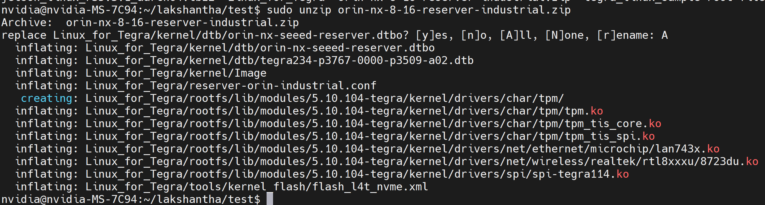
- Step 3: Extract the downloaded driver .zip file. Here we additionally install the unzip package which is needed to decompress the .zip file
sudo apt install unzip
sudo unzip xxxx.zip # Replace xxxx with the driver file name
Here it will ask whether to replace the files. Type A and press ENTER to replace the necessary files
Flash to Jetson
- Step 1: Navigate to the Linux_for_Tegra directory and execute the flash command as follows
cd Linux_for_Tegra
sudo ./tools/kernel_flash/l4t_initrd_flash.sh --external-device nvme0n1p1 -c tools/kernel_flash/flash_l4t_nvme.xml -S 80GiB  -p "-c bootloader/t186ref/cfg/flash_t234_qspi.xml --no-systemimg" --network usb0  reserver-orin-industrial external
Now it will start to flash the system image to the board. If the flashing is successful, you will see the below output
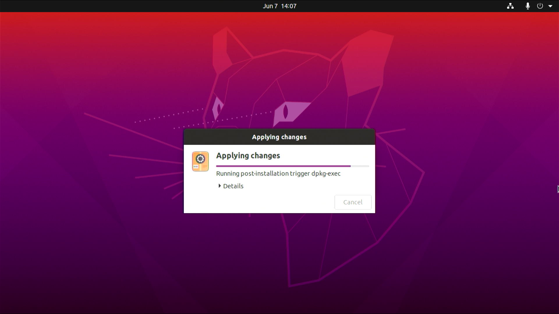
- Step 2: Connect the board to a display using the HDMI connector on the board and finish the initial configuration setup
After that, the board will reboot and you will see the following
- Step 3: Open a terminal window inside the device, execute the following, the device will reboot and ready to use!
systemctl disable nvgetty.service
sudo depmod -a
sudo reboot
Futhermore, if you want to install SDK components such as CUDA, cuDNN, TensorRT, please execute the following
sudo apt update
sudo apt install nvidia-jetpack -y
Hardware and Interfaces Usage
To learn more about how to use all the hardware and interfaces on the reServer Industrial board, we recommend you to follow the below section of the wiki:
Disassemble reServer Industrial
First of all, it is better to disassemble the outer enclosure to access all the interfaces. Follow this document to learn more.
Gigabit Ethernet Connectors
There are 5 Ethernet ports on the reServer Industrial with 10/100/1000Mbps specification and 4 of them are rated with PSE 802.3 af 15 W where you can directly connect PoE cameras to these ports (LAN1-LAN4). These are connected via a PCIe to Ethernet (LAN7430-I/Y9X) module. However, the remaining Ethernet port (LAN0) on the leftmost side is only used to connect to a router for internet.
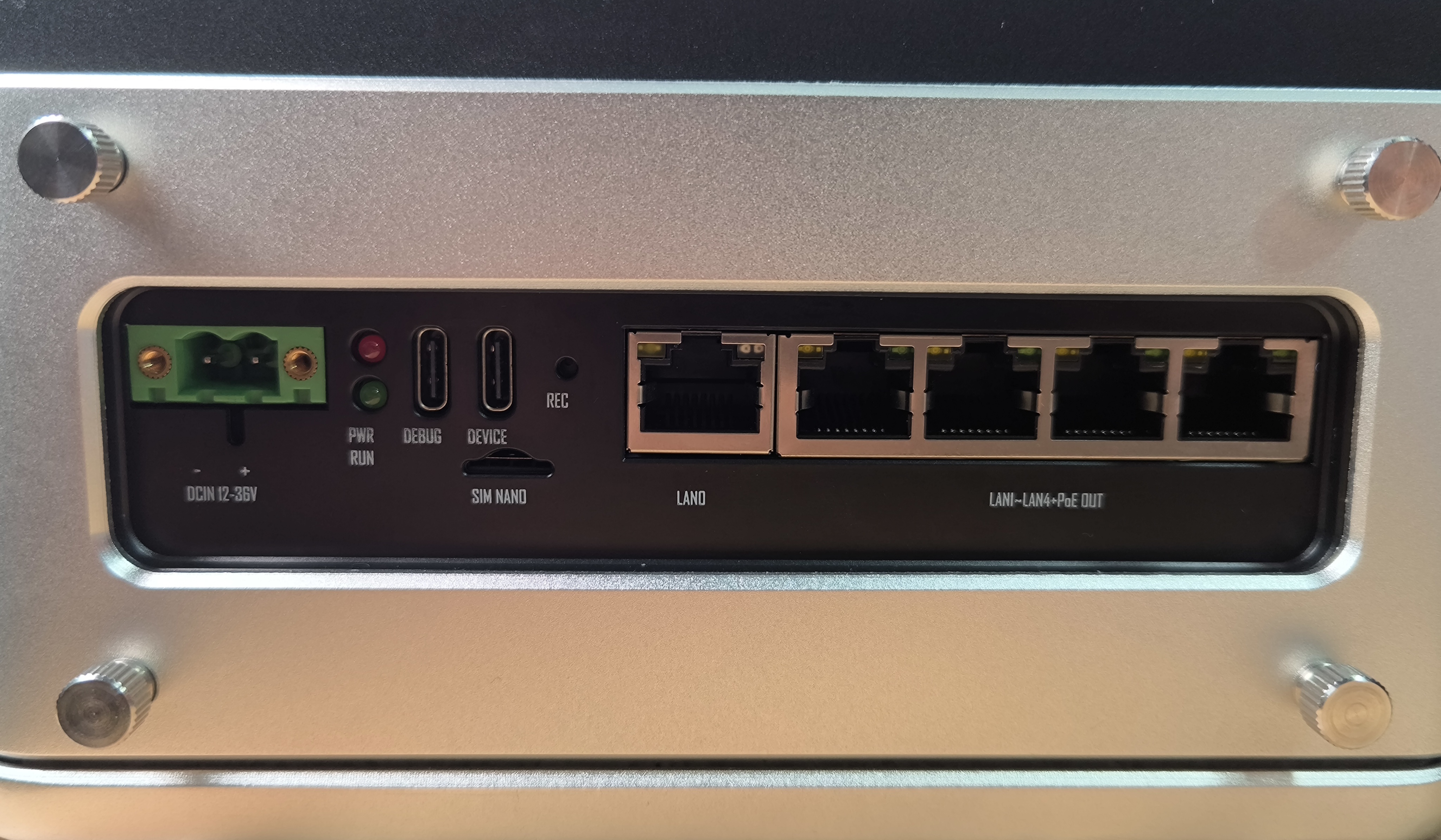
There are 2 LEDs (green and yellow) on each Ethernet port which indicates the following
- Green LED: ON only when connected to 1000M network
- Yellow LED: Shows the network activity status
Usage
Before connecting PoE cameras, you need to enable the PoE function for the 4 Ethernet ports. Enable it as follows:
sudo -i
cd /sys/class/gpio
echo 315 > export
cd gpio315
echo "out" > direction
echo 1 > value
SATA Connectors
reServer Industrial supports 2 SATA 2.5" HDD/SSD and comes with both SATA data and power connectors. You can connect to HDD/ SSD as follows
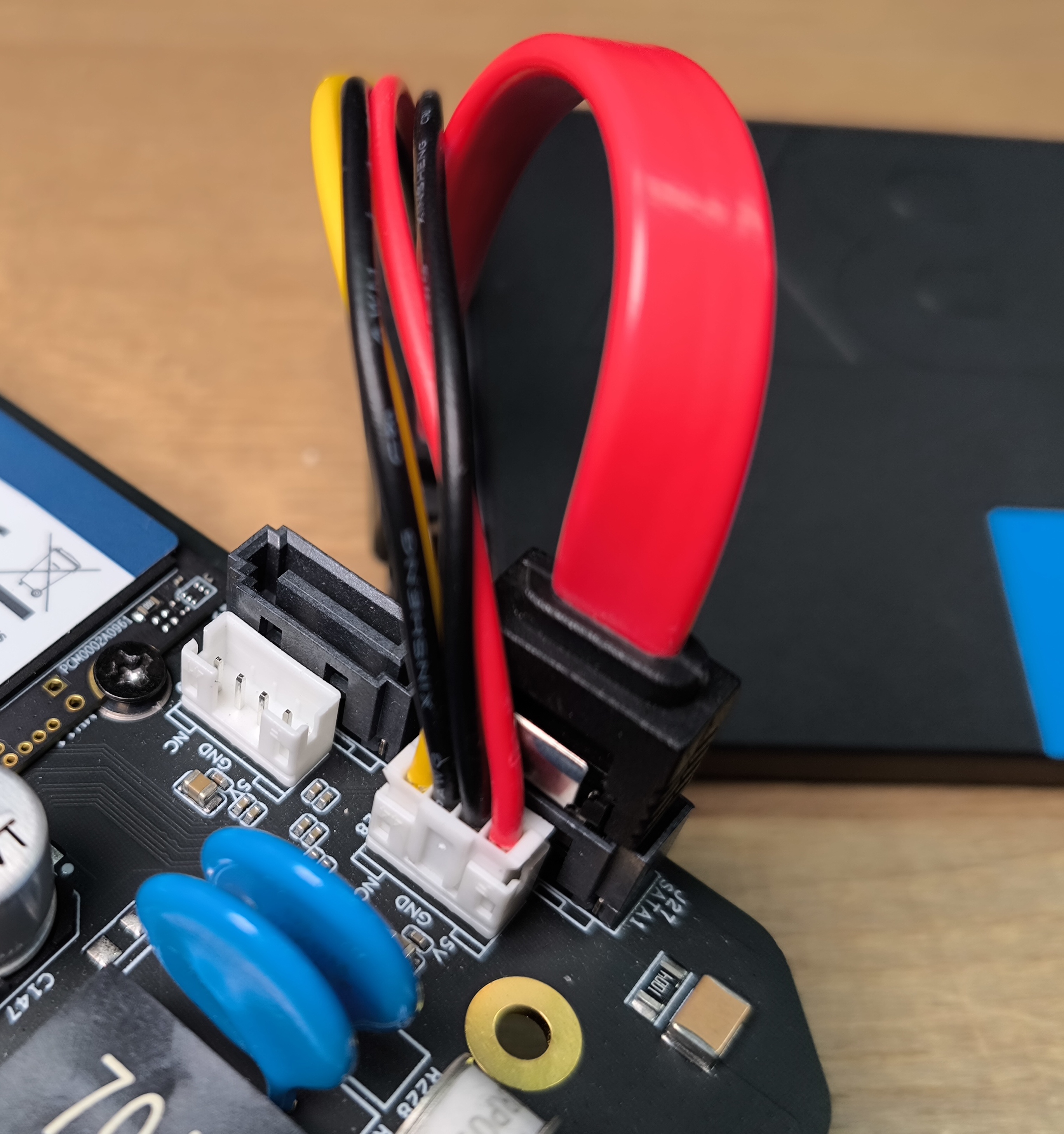
Usage
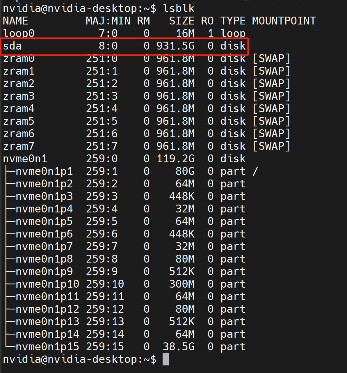
After the system boots up, you can verify the connected SATA drives by
lsblk
RTC
reServer Industrial is equipped with 2 different ways to connect to an RTC battery
Connection Overview
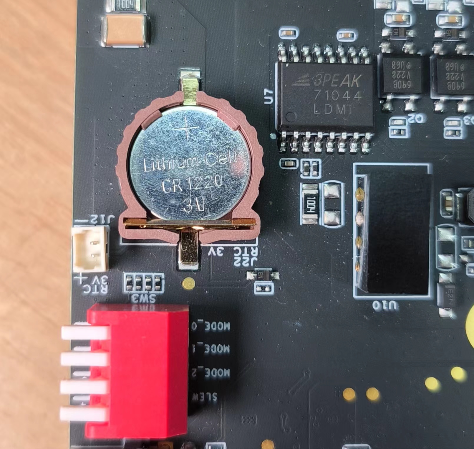
- Method 1:
Connect a 3V CR1220 coin cell battery to the RTC socket on the board as shown below. Make sure the positive (+) end of the battery is facing upwards
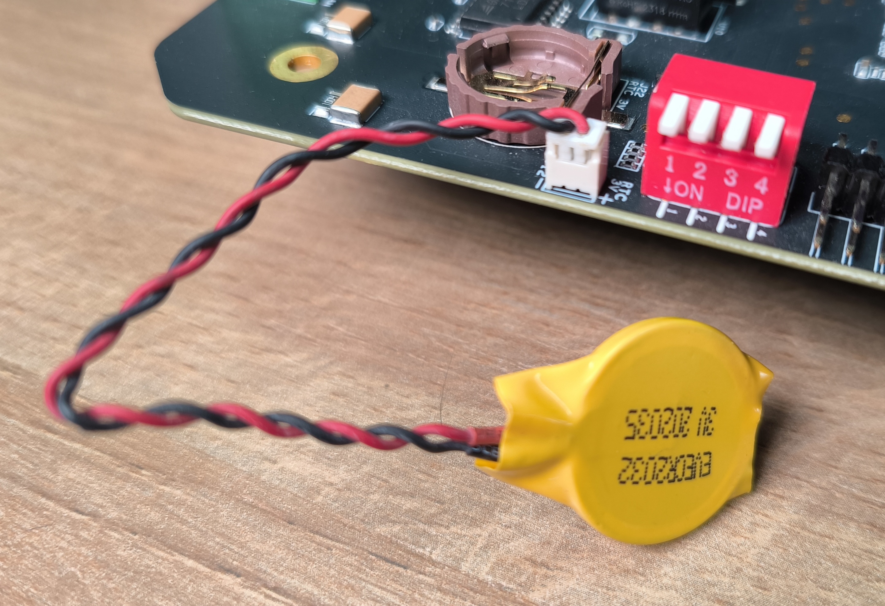
- Method 2:
Connect a 3V CR2302 coin cell battery with JST connector to the 2-pin 1.25mm JST socket on the board as shown below
Usage
Step 1: Connect an RTC battery as mentioned above
Step 2: Turn on reServer Industrial
Step 3: On the Ubuntu Desktop, click the drop-down menu at the top right corner, navigate to
Settings > Date & Time, connect to a network via an Ethernet cable and select Automatic Date & Time to obtain the date/ time automatically
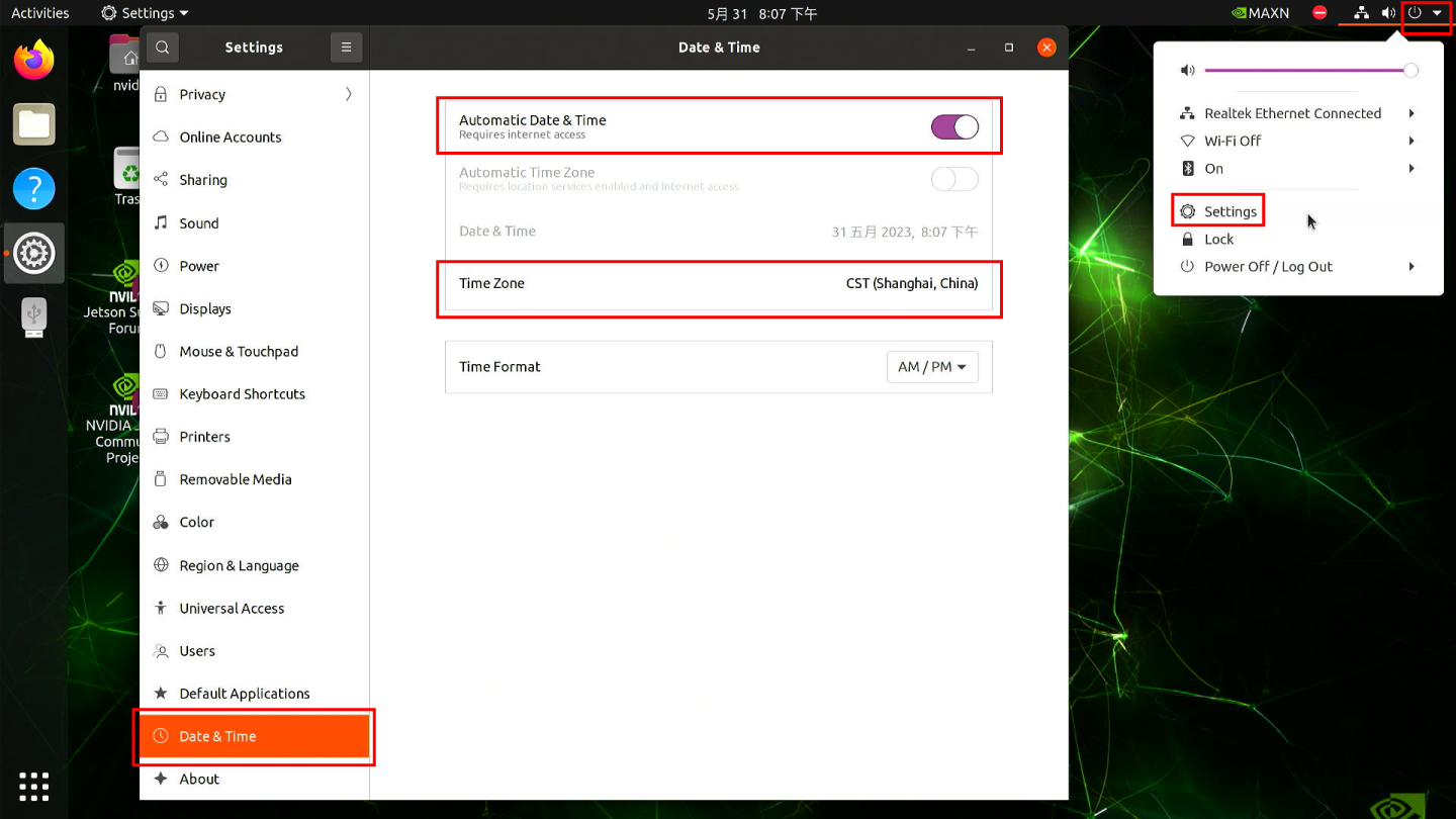
If you have not connected to internet via Ethernet, you can manually set the date/ time here
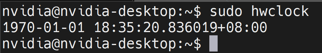
- Step 4: Open a terminal window, and execute the below command to check the hardware clock time
sudo hwclock
You will see the output something like below which is not the correct date/ time
- Step 5: Change the hardware clock time to the current system clock time by entering the below command
sudo hwclock --systohc
- Step 6: Remove any Ethernet cables connected to make sure it will not grab the time from the internet and reboot the board
sudo reboot
- Step 7: Check hardware clock time to verify that the date/ time stays the same eventhough the device was powered off
Now we will create a script to always sync the system clock from the hardware clock in each boot.
- Step 8: Create a new shell script using any text editor of your preference. Here we use vi text editor
sudo vi /usr/bin/hwtosys.sh
- Step 9: Enter insert mode by pressing i, copy and paste the following content inside the file
#!/bin/bash

sudo hwclock --hctosys
- Step 10: Make the script executable
sudo chmod +x /usr/bin/hwtosys.sh
- Step 11: Create a systemd file
sudo nano /lib/systemd/system/hwtosys.service
- Step 12: Add the following inside the file
[Unit]
Description=Change system clock from hardware clock

[Service]
ExecStart=/usr/bin/hwtosys.sh

[Install]
WantedBy=multi-user.target
- Step 13: Reload systemctl daemon
sudo systemctl daemon-reload
- Step 14: Enable the newly created service to start on boot and start the service
sudo systemctl enable hwtosys.service
sudo systemctl start hwtosys.service
- Step 15: Verify the script is up and running as a systemd service
sudo systemctl status hwtosys.service
- Step 16: Reboot the board and you will the system clock is now in sync with the hardware clock
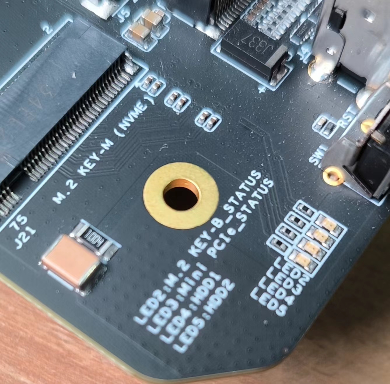
M.2 Key M
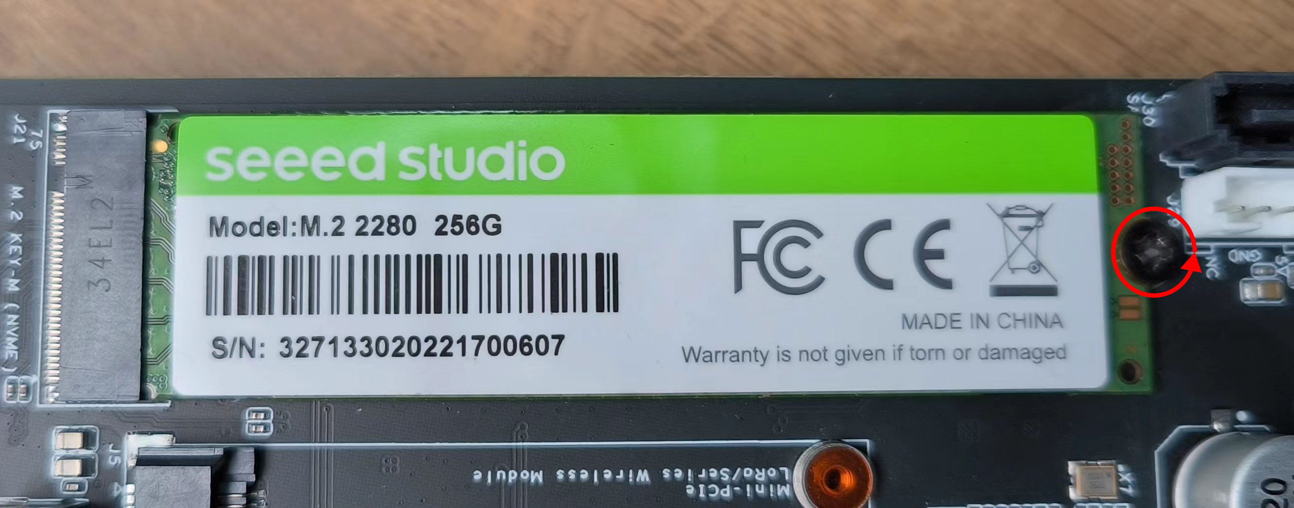
Out of the box, reServer Industrial includes a 128GB SSD connected to the M.2 Key M slot, which is pre-installed with JetPack system.
Connection Overview
If you want to remove the included SSD and install a new one, you can follow the steps below. Here we only recommend to use Seeed SSDs with 128GB, 256GB, 512GB and 1TB storage because we have only tested those SSDs. Further this interface supports PCIe Gen4.0 SSDs.
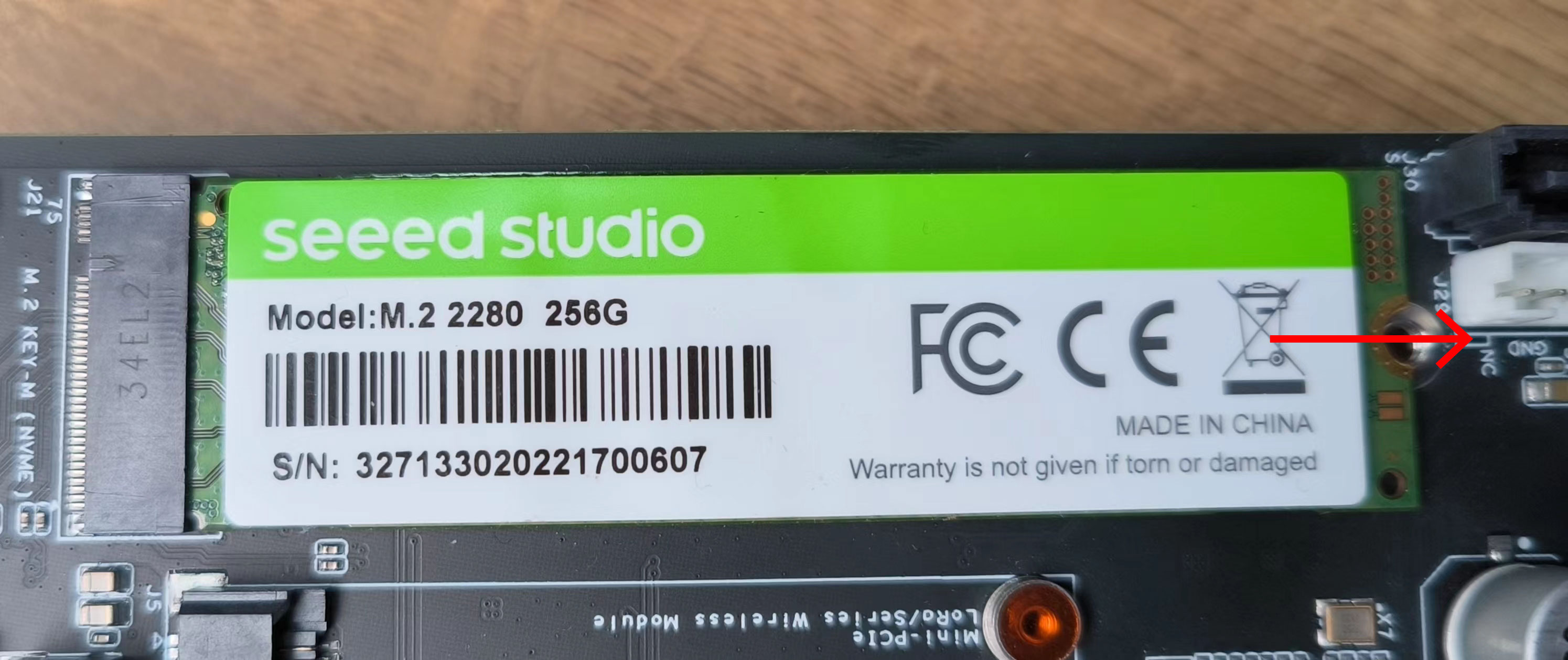
- Step 1: Remove the pre-installed SSD screw
- Step 2: Remove the SSD by sliding away from the SSD connector
- Step 3: Insert a new SSD and tighten back the screw
Usage
We will explain how to do a simple benchmark on the connected SSD
- Step 1: Check the write speed by executing the below command
sudo dd if=/dev/zero of=/home/nvidia/test bs=1M count=512 conv=fdatasync
- Step 2: Check the read speed by executing the below commands. Make sure to execute this after executing the above command for write speed.
sudo sh -c "sync && echo 3 > /proc/sys/vm/drop_caches"
sudo dd if=/home/nvidia/test of=/dev/null bs=1M count=512
mini PCIe
reServer Industrial comes with a mini PCIe connector that supports 4G and LoRa modules. However, you can only connect either a 4G module or a LoRa module at once. Some of the 4G modules come embedded with GPS functionality. We will discuss this as well.
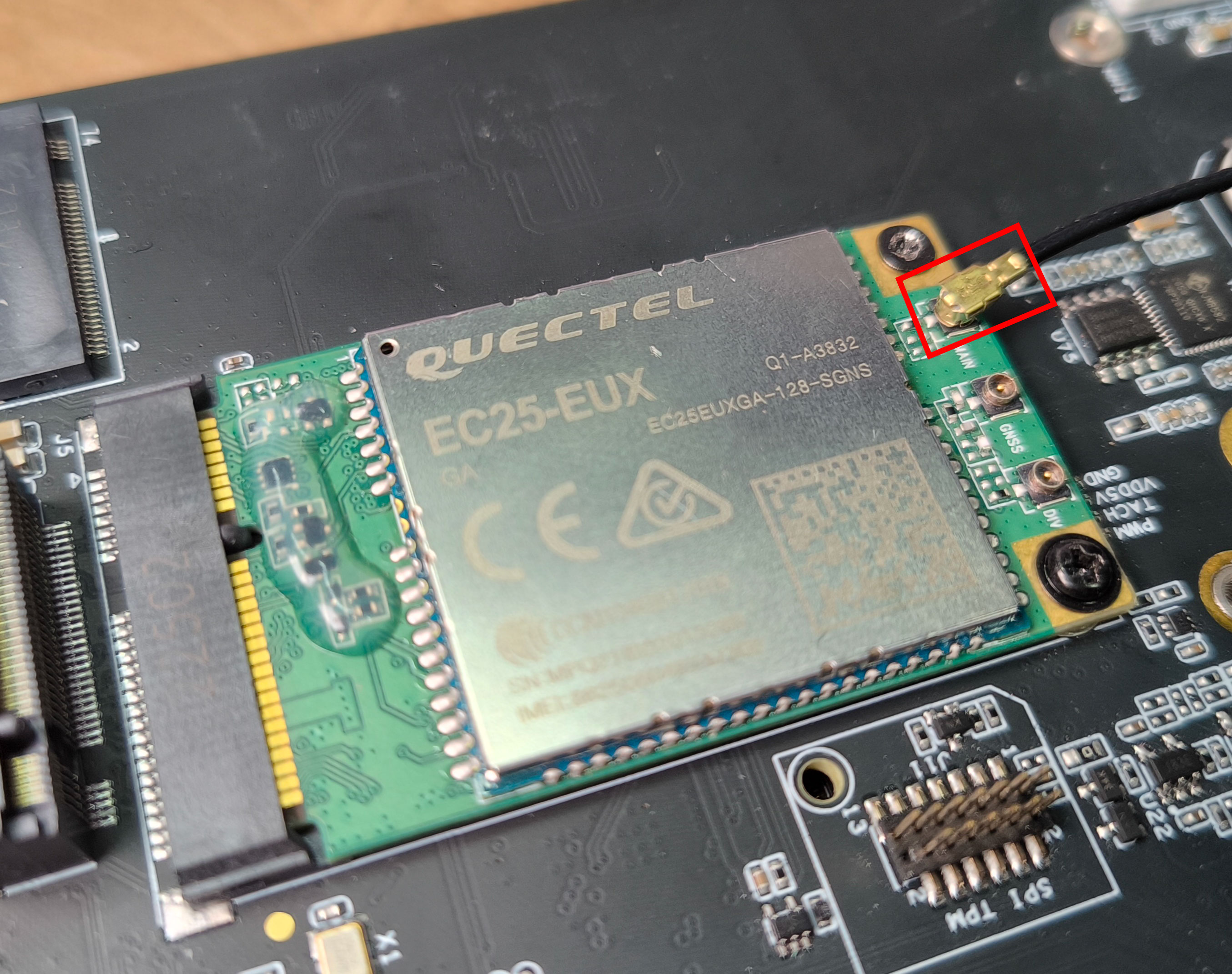
4G Module Connection Overview
Currently this board supports EC25EUXGA and EC20CEHCLG modules.
Step 1: Power off the board if it is already on
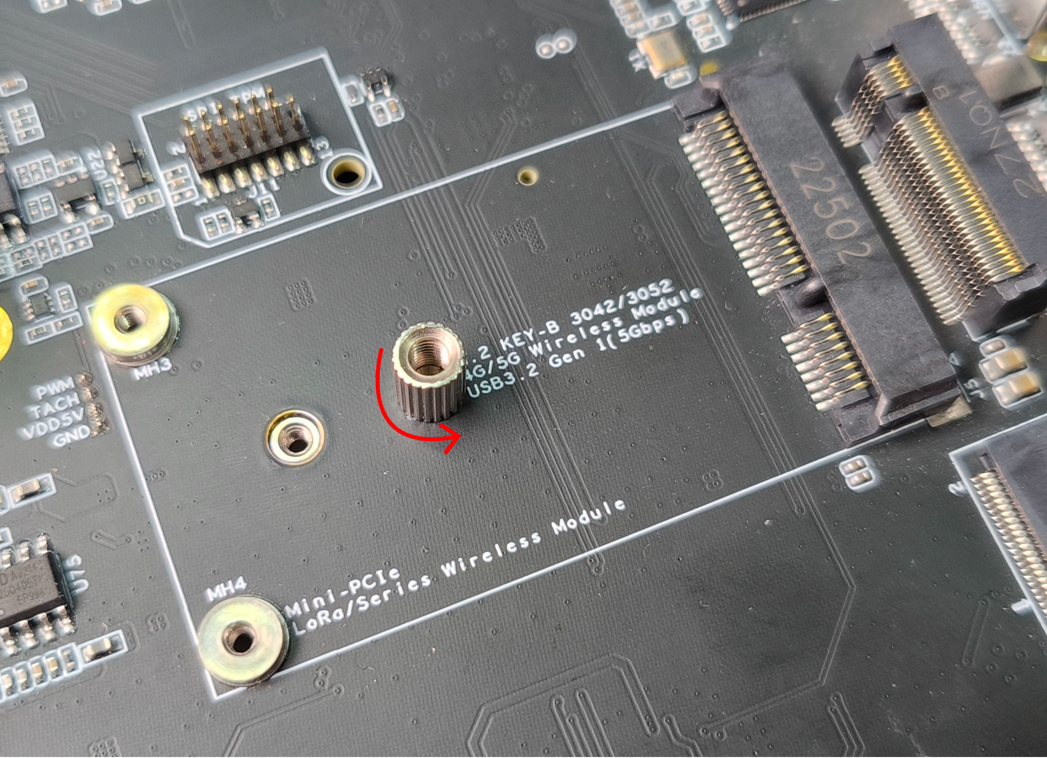
Step 2: Remove the included standoff. This standoff is only needed if you are using the M.2 Key B interface
- Step 3: Slide in the 4G module to the mini PCIe slot, use the pre-installed screws and screw them to the 2 holes to secure the 4G module in place
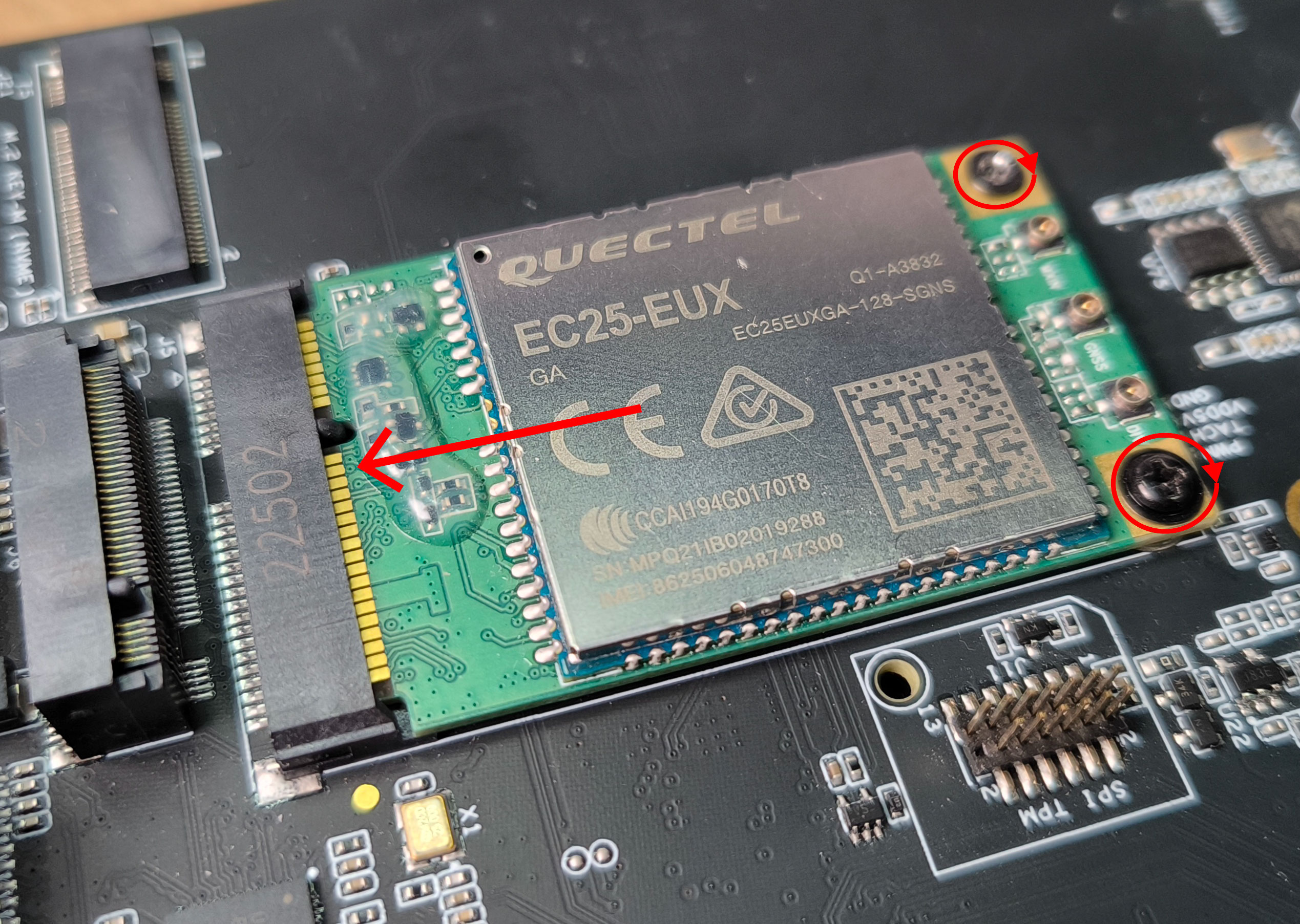
- Step 4: Connect an antenna to the the antenna connector labelled as MAIN. Here you need to use an IPEX connector
- Step 5: Insert a 4G-enabled nano SIM card to the SIM card slot on the board making sure the gold surface of the SIM card is facing up. Here insert the card all the way in so that it will bounce back after hitting the internal spring and lock in place.
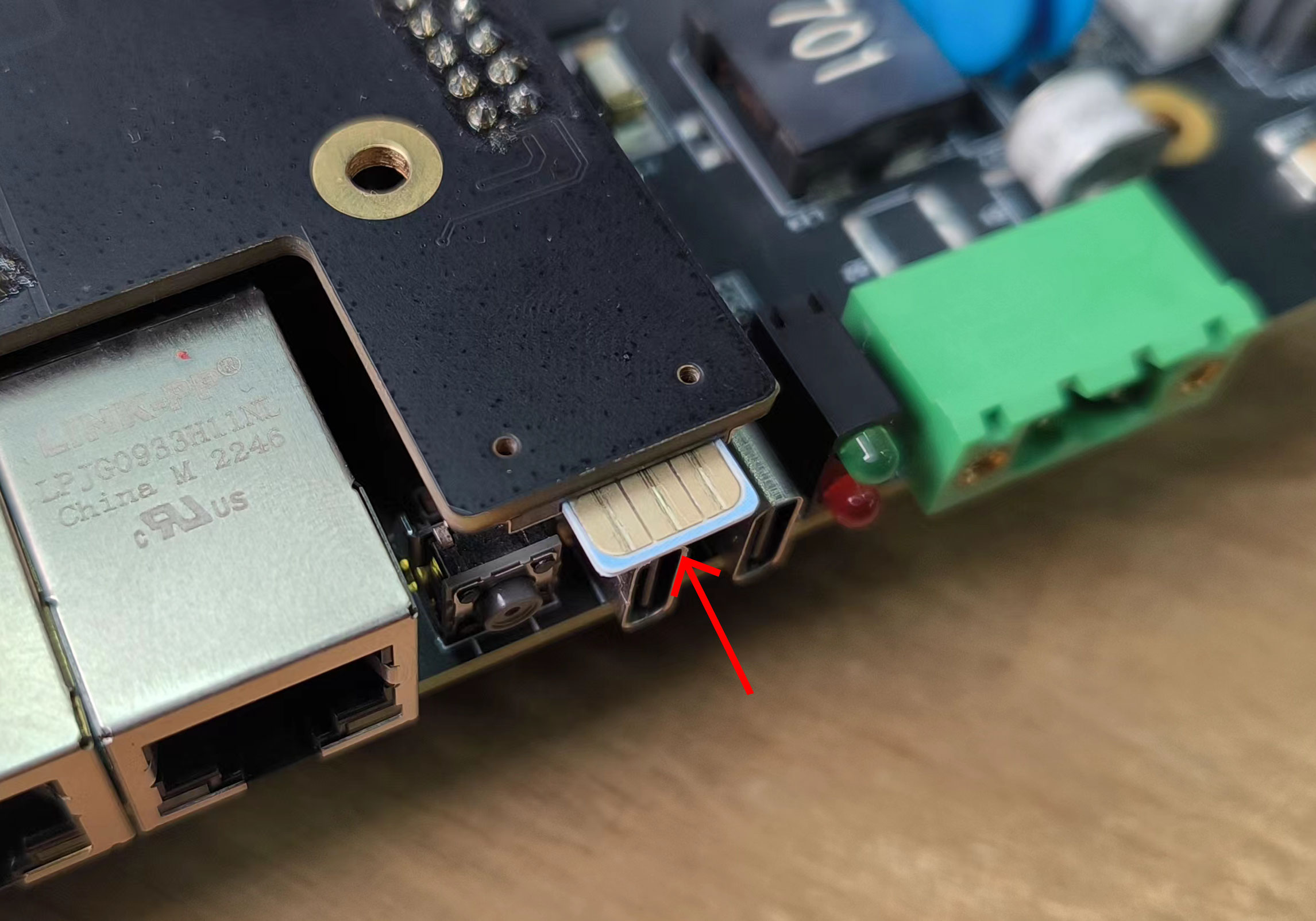
If you want to remove the SIM card, push the card in to hit the internal spring so that the SIM will come out of the slot
- Step 6: Add a jumper between SIM_MUX_SEL and GND pins on the J8 (Control and UART) Header
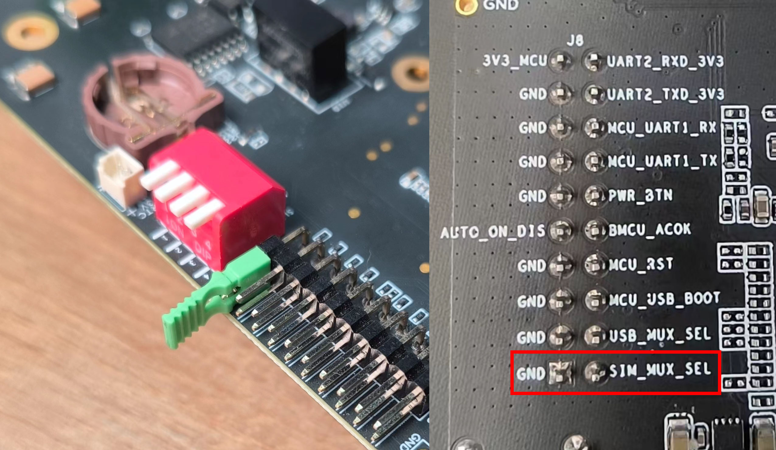
- Step 6: Power on the board
4G Module Usage - Test Dialing
When using the EC25 module, the module will automatically start and will be ready to use. However, when using the EC20 module, you need to reset the module for it to work
- Step 1: If you are using EC25 module, you can skip this step. However if you are using EC20 module, enter the following commands to access GPIO309 pin which is responsible to reset the 4G module
sudo su
cd /sys/class/gpio
echo 309 > export
cd gpio309
echo out > direction
echo 1 > value
For EC25 module, LED2 will light up in green as soon as the board is booted up. For EC20 module, LED2 will light up in green after resetting the module as explained above
- Step 2: Install minicom
sudo apt update
sudo apt install minicom -y
- Step 3: Enter the serial console of the connected 4G module so that we can enter AT commands and interact with the 4G module
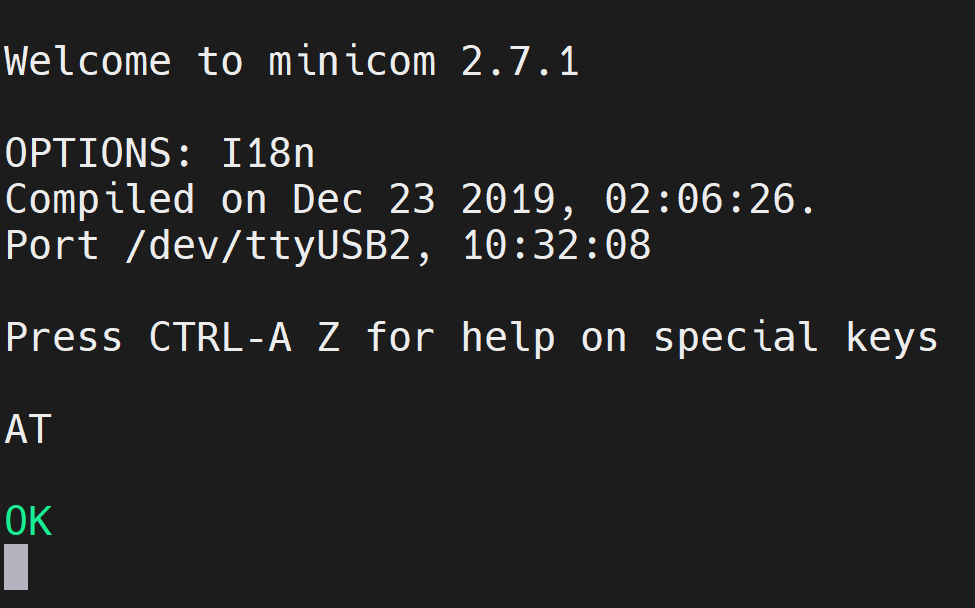
sudo minicom -D /dev/ttyUSB2 -b 115200
Step 4: Press Ctrl+A and then press E to turn on local echo
Step 5: Enter the command "AT" and press enter. If you see the response as "OK", the 4G module is working properly
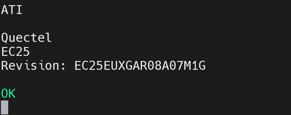
- Step 6: Enter the command "ATI" to check the module information
- Step 7: To test the module, enter the below command to call another phone number
ATD<phone_number>;
And you will see the below output
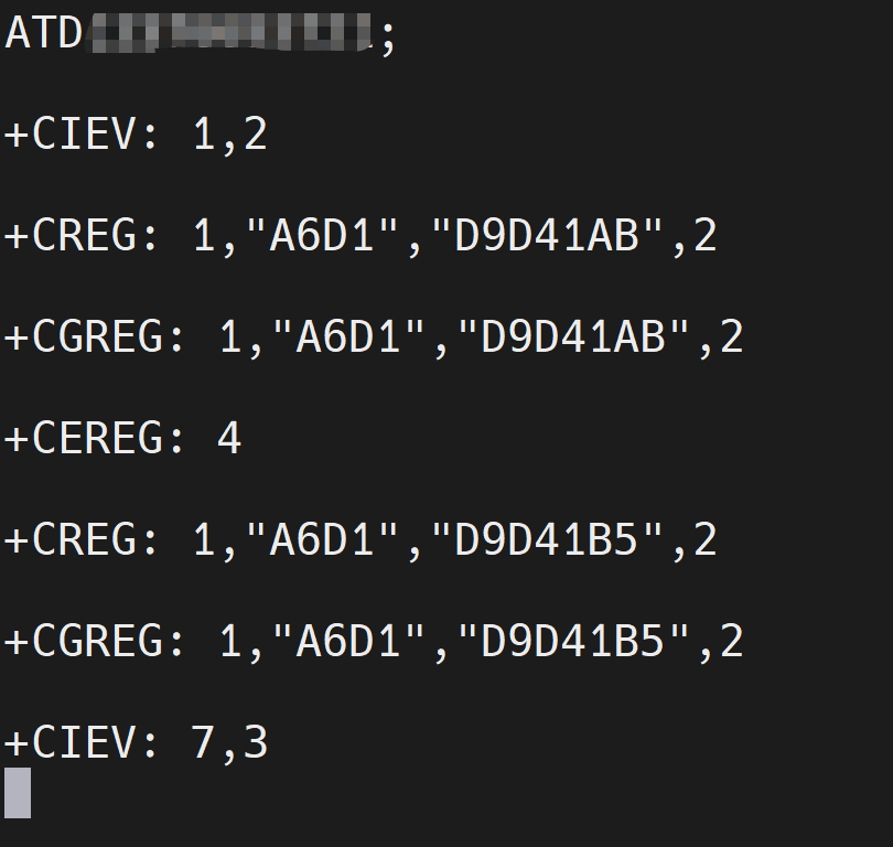
If the entered phone number can receive the call, the module is working as expected
4G Module Usage - Connect to Internet
EC25 module
If you are using the EC25 module, follow the below steps
- Step 1: After opening the serial console of the 4G module as explained above (4G Module Usage - Test Dialing section), execute the following command to connect to the internet. Here replace YOUR_APN with the APN of your network provider
AT+CGDCONT=1,"IP","YOUR_APN"
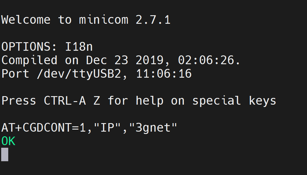
On successful connection, it should output OK as you can see from the image above
- Step 2: Restart the 4G module by executing the following
AT+CFUN=1,1
Now you will lose connection to the 4G module on the serial terminals
Step 3: Close minicom by pressing CTRL + A and then Q
Step 4: Type ifconfig and you will see an IP address on the usb0 interface
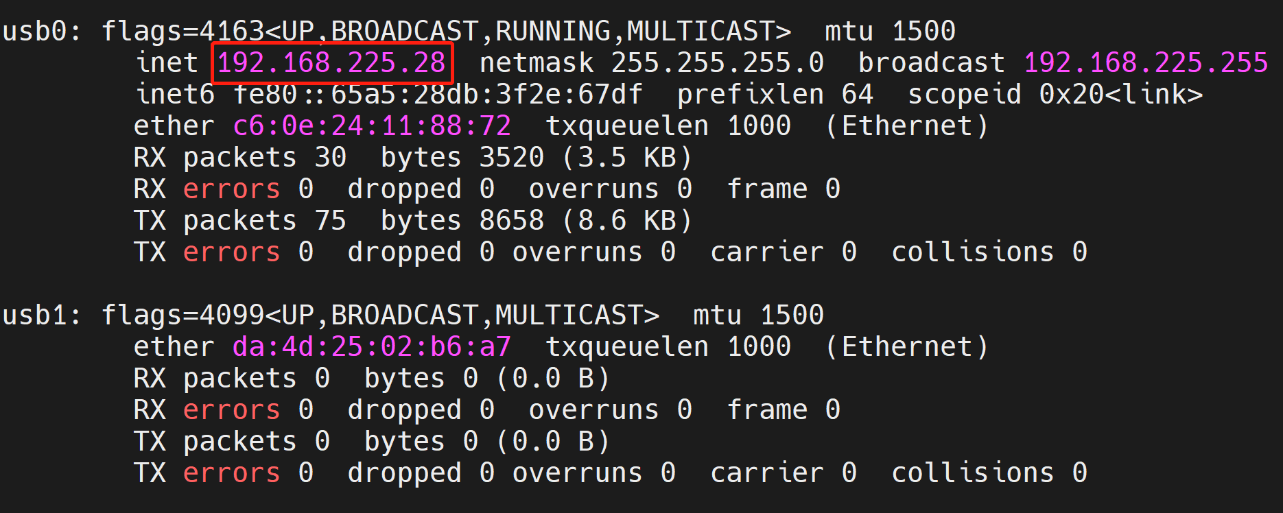
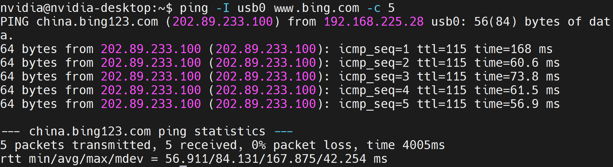
- Step 5: You can try to ping a website as follows to check whether there is internet connectivity
ping -I usb0 www.bing.com -c 5
EC20 module
If you are using the EC20 module, follow the below steps
Step 1: If you have already reset the 4G module as explained in the previous section (4G Module Usage - Test Dialing section) for EC20 module, you can skip this step. However, if you have not yet done it, please do it now
Step 2: Enter the serial console of the 4G module and enter the following command to set to ECM mode
AT+QCFG="usbnet",1
Step 3: Reset the 4G module
Step 4: Inside the 4G module console, execute the following command to connect to the internet. Here replace YOUR_APN with the APN of your network provider
AT+CGDCONT=1,"IP","YOUR_APN"
- Step 6: Type ifconfig and you will see an IP address on the usb1 interface
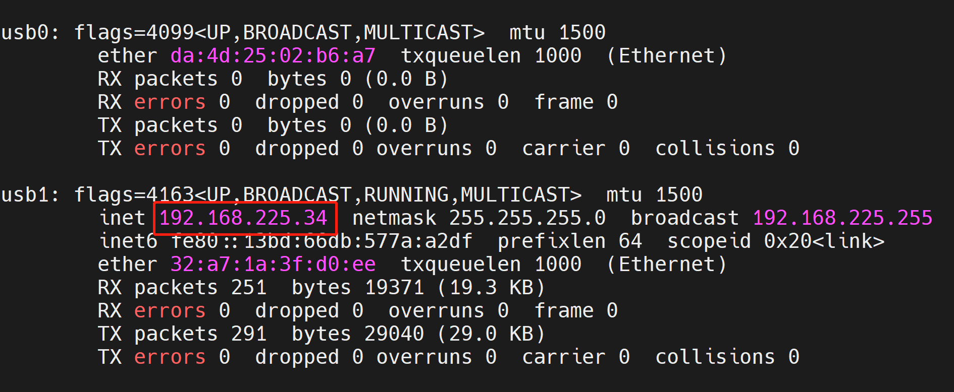
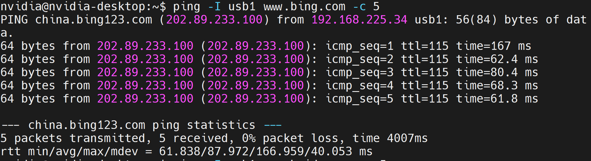
- Step 7: You can try to ping a URL as follows to check whether there is internet connectivity
4G Module Usage - Connect to GPS
Some 4G modules comes with GPS modules embedded in them. Both EC25EUXGA and EC20CEHCLG modules come with 4G modules in them.
- Step 1: Restart the GPS module by executing the below commands
echo -e "AT+QGPS=1\r\n" > /dev/ttyUSB2
echo -e "AT+QGPS=0\r\n" > /dev/ttyUSB2
- Step 2: Obtain the GPS data by executing the below commands
sudo cat /dev/ttyUSB1
And you will see an output as follows
seeed@seeed-x:~$ sudo cat /dev/ttyUSB1
[sudo] password for seeed:
$GPVTG,,T,,M,,N,,K,N*2C
$GPGSA,A,1,,,,,,,,,,,,,,,,*32
$GPGGA,,,,,,0,,,,,,,,*66
$GPRMC,,V,,,,,,,,,,N*53
$GPVTG,,T,,M,,N,,K,N*2C
$GPGSA,A,1,,,,,,,,,,,,,,,,*32
$GPGGA,,,,,,0,,,,,,,,*66
$GPRMC,,V,,,,,,,,,,N*53
$GPVTG,,T,,M,,N,,K,N*2C
LoRa Module Connection Overview
Currently this board supports WM1302 SPI module. You can either use US version or EU version which is available on our Bazaar.
Step 1: Power off the board if is already on
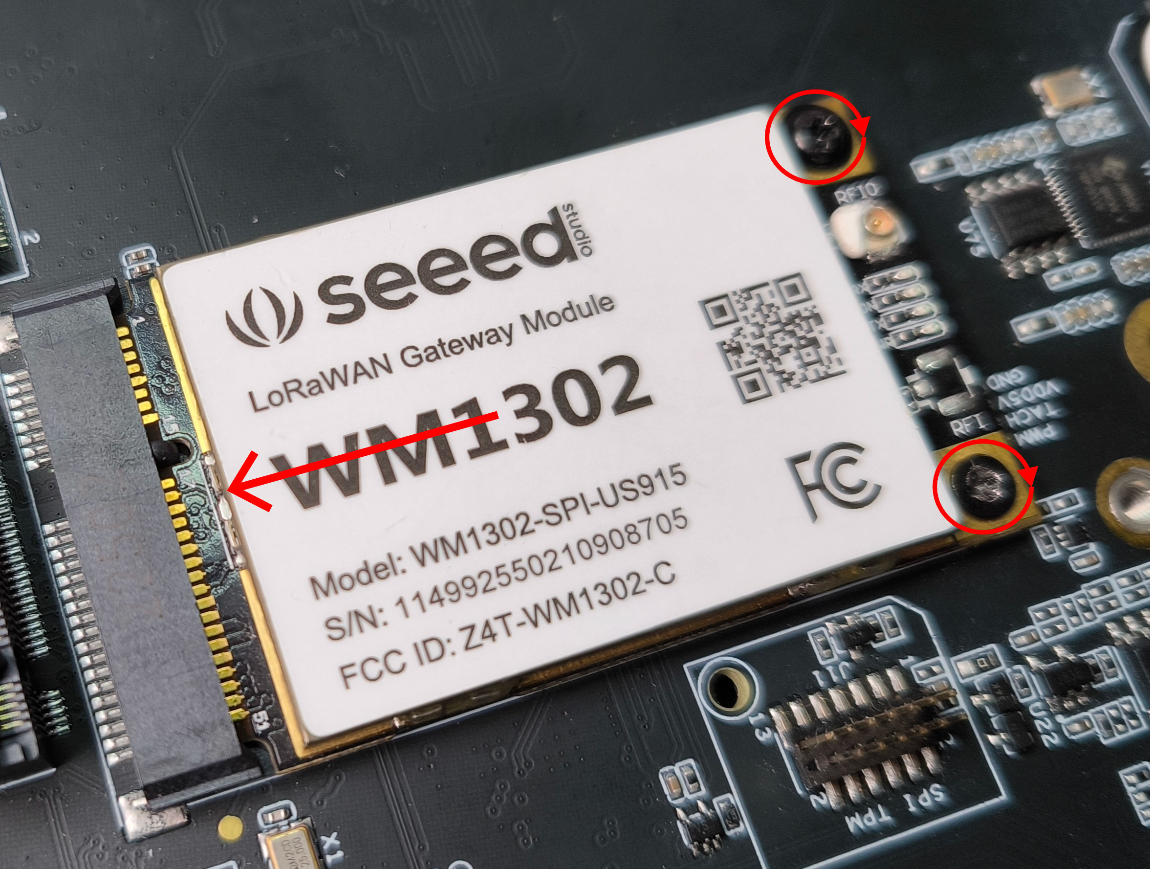
Step 2: Slide in the LoRa module to the mini PCIe slot and use the pre-installed screws and screw them to the 2 holes to secure the LoRa module in place
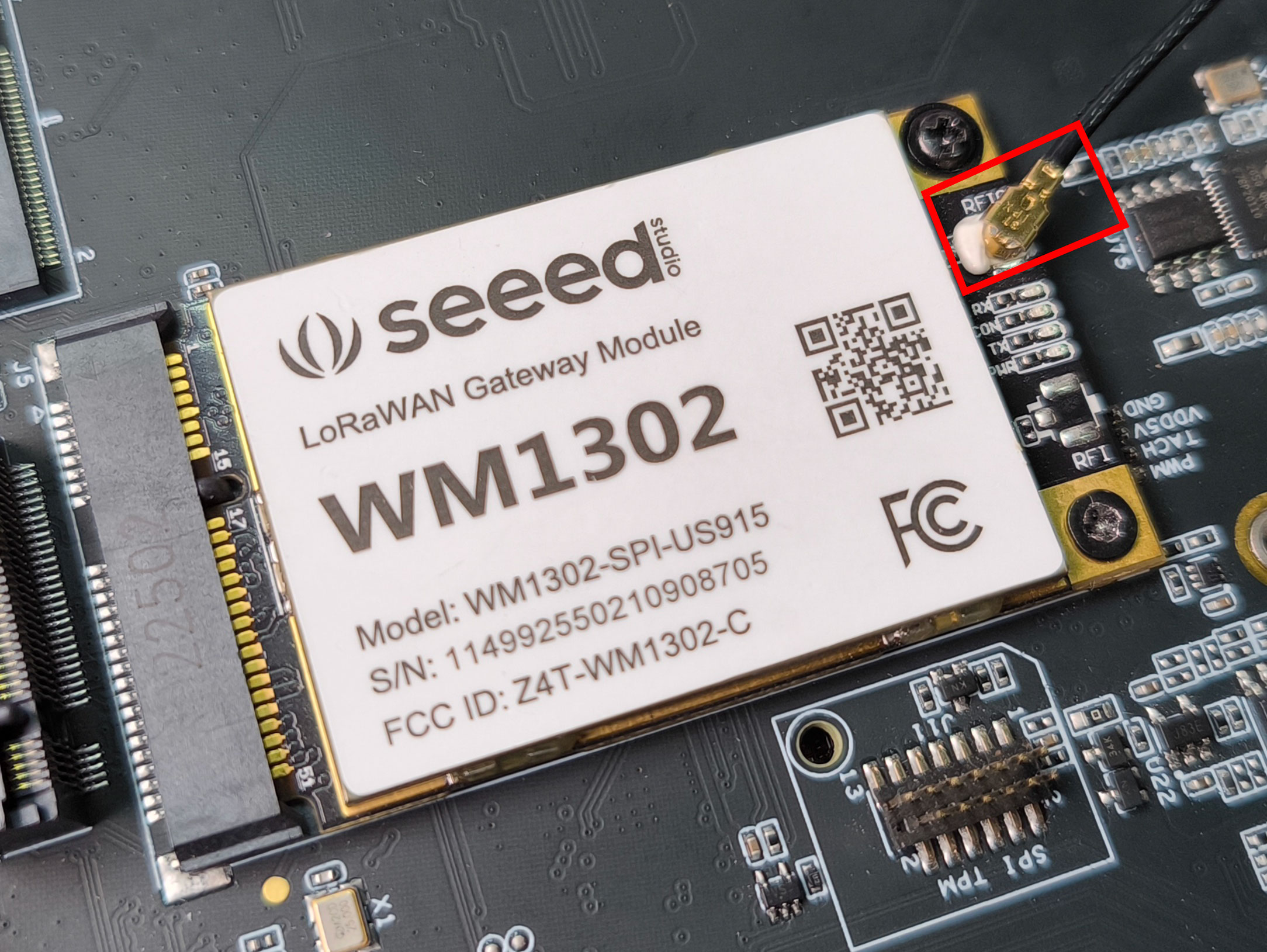
- Step 3: Connect an antenna to the the antenna connector. Here you need to use an IPEX connector
Make sure there is no jumper between SIM_MUX_SEL and GND pins on the J8 (Control and UART) Header. This jumper is only needed when using 4G modules
- Step 4: Power on the board
LoRa Module Usage - Testing LoRa RF
When the LoRa module is connected, you will see the green and blue LEDs on the module light up
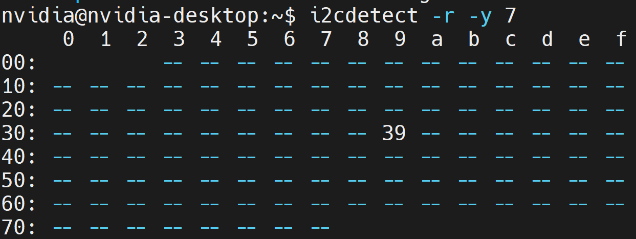
- Step 1: Enter the below command to check whether the LoRa module is detected by the system
i2cdetect -r -y 7
If you see the below output, the module is detected by the system
- Step 2: Enter the below commands to compile and build the LoRa signals transmitting tool
git clone https://github.com/lakshanthad/sx1302_hal
cd sx1302_hal
make
cd libloragw
cp ../tools/reset_lgw.sh .
sudo ./test_loragw_hal_tx -r 1250 -m LORA -f 867.1 -s 12 -b 125 -n 1000 -z 100 --dig 3 --pa 0 --pwid 13 -d /dev/spidev2.0
If you see the below result and the LED on the LoRa module turns RED, that means the module is trasmitting RF signals successfully
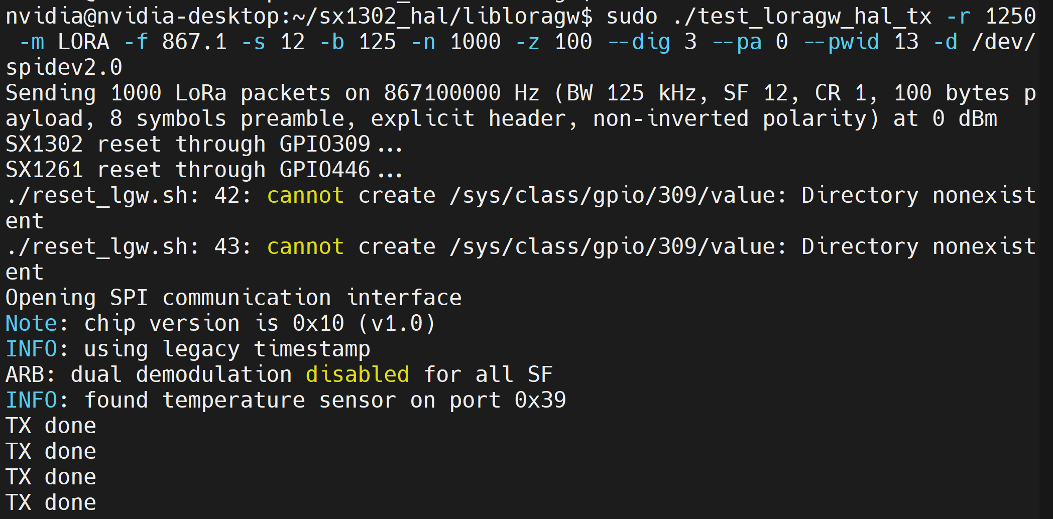
To stop transmitting, you can press CTRL + C on the keyboard.
LoRa Module Usage - Connect to TTN
Now we will connect to TTN (The Things Network) and use the reServer Industrial as a TTN LoRaWAN gateway
- Step 1: Enter the below to make the packet forwarder ready
cd ..
cd packet_forwarder
cp ../tools/reset_lgw.sh .
- Step 2: Run the following according to the LoRa module you are using. Here we have tested SPI US915 version
sudo ./lora_pkt_fwd -c global_conf.json.sx1250.US915
However, the commands for different other modules are as follows
# USB 915
sudo ./lora_pkt_fwd -c global_conf.json.sx1250.US915.USB

# SPI EU868
sudo ./lora_pkt_fwd -c global_conf.json.sx1250.EU868

# USB EU868
sudo ./lora_pkt_fwd -c global_conf.json.sx1250.EU868.USB
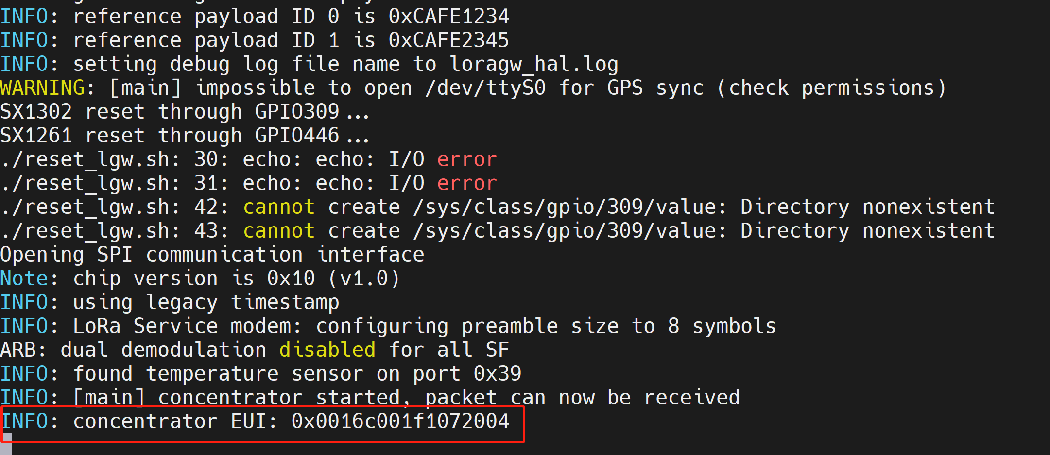
After running the above command, you will see the below output with last line showing the concentrator EUI information. Please keep this information because we will use it later when setting up the gateway with TTN
- Step 3: Visit this URL to enter the TTN console and select a region of your choice
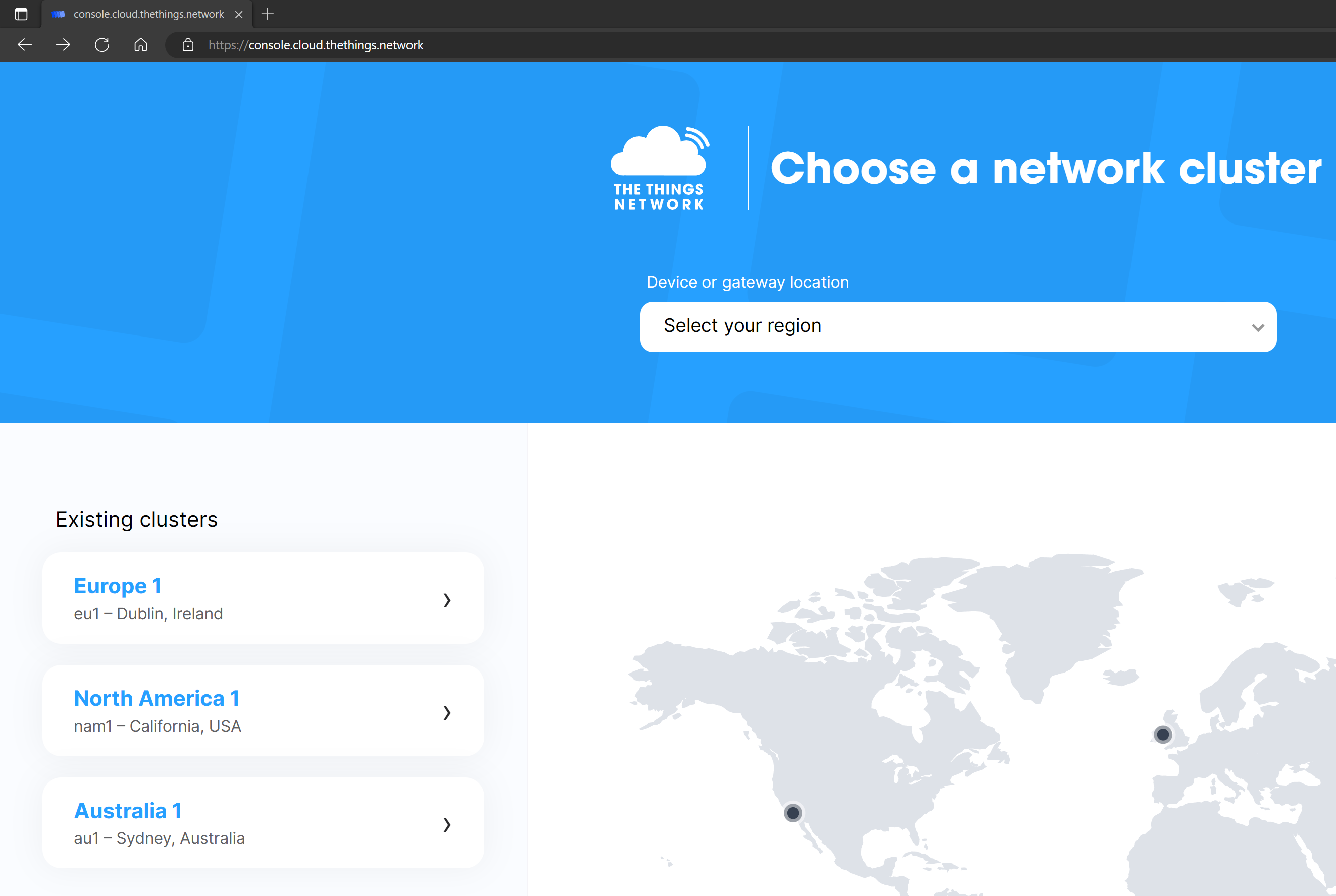
- Step 4: Login if you already have an account, or sign up for a new account if you do not have one

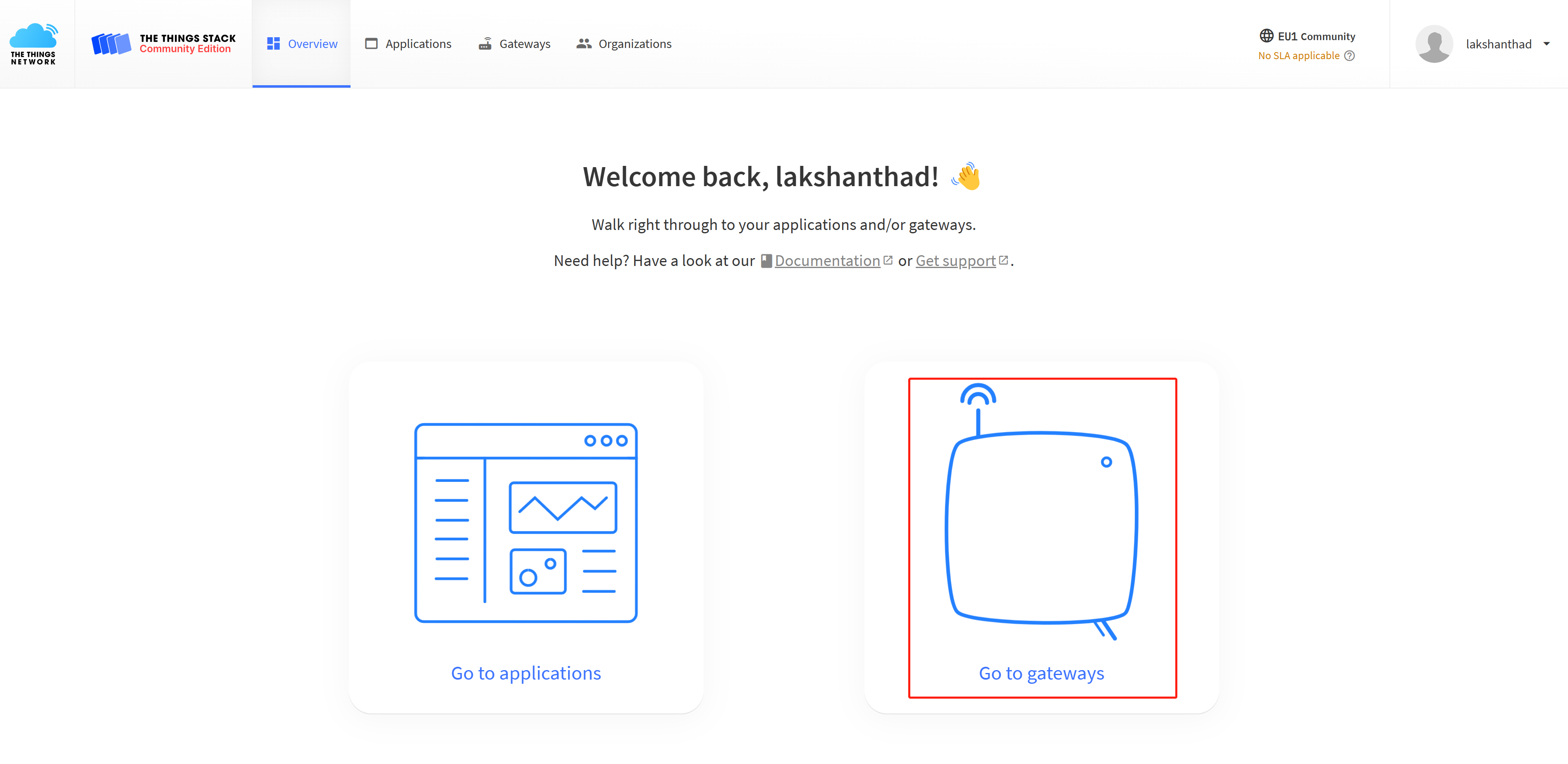
- Step 5: Click Go to gateways
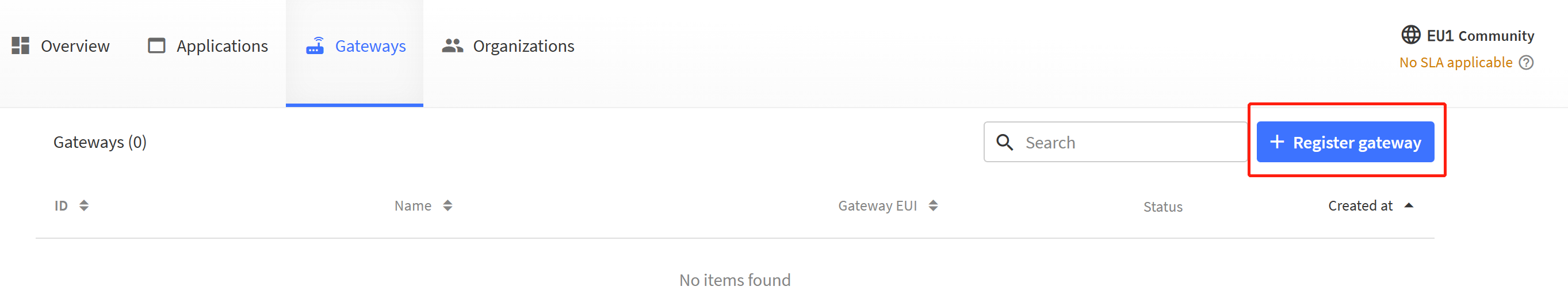
- Step 6: Click + Register gateway
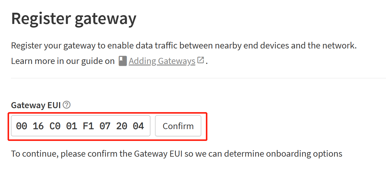
- Step 7: Enter the Concentrator EUI that you obtained before inside the Gateway EUI section and click Confirm
- Step 8: Enter the Frequency plan according to the LoRa module you are using. Here we are using US915 verison of the module and therefore have selected United Stated 902-928 MHz, FSB 2 (used by TTN). After that click Register gateway
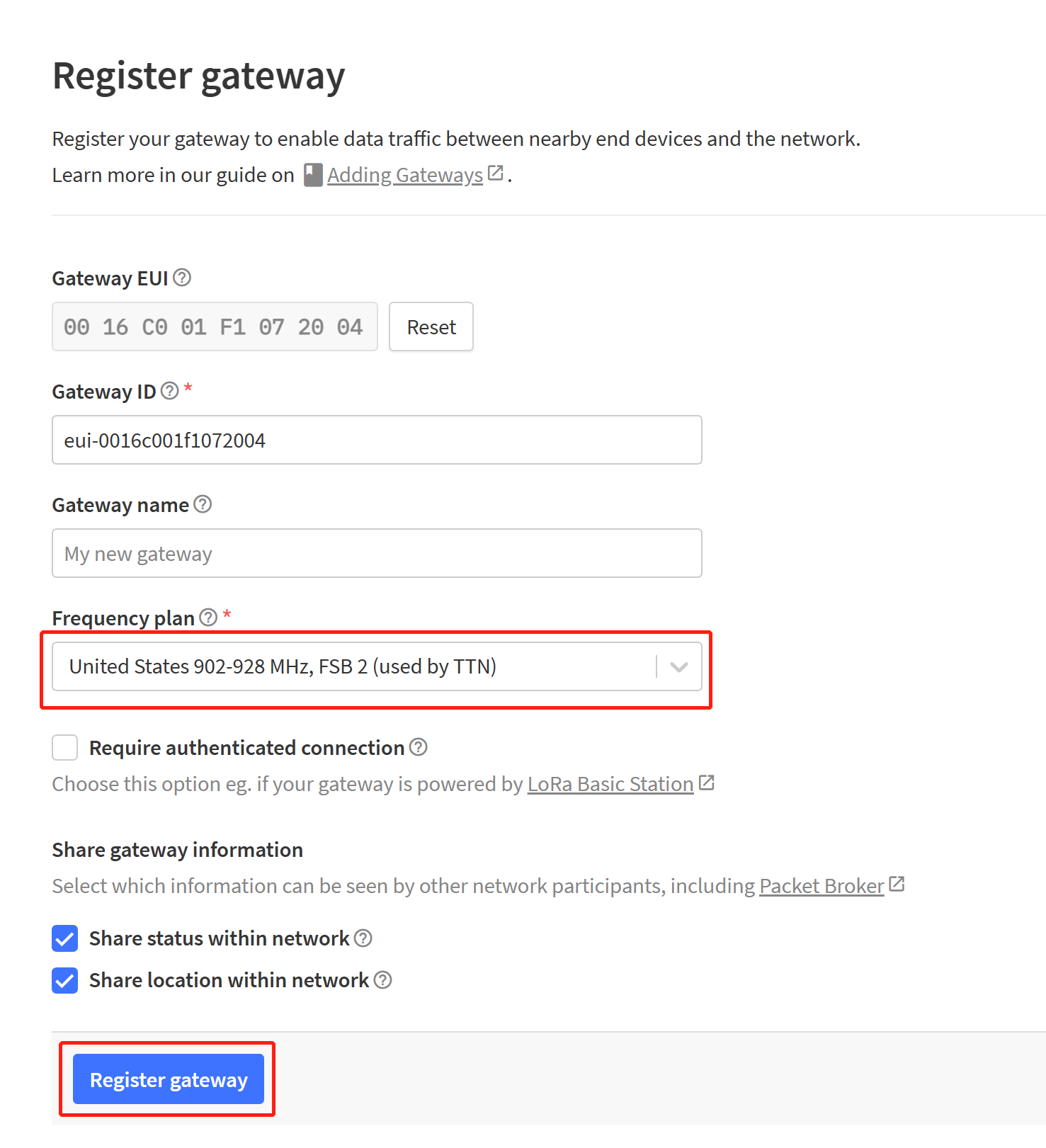
The Gateway ID has been filled automatically for you. However, you can change it to anything you prefer. Gateway name is not a must to fill. However, you can fill it as well according to your preference
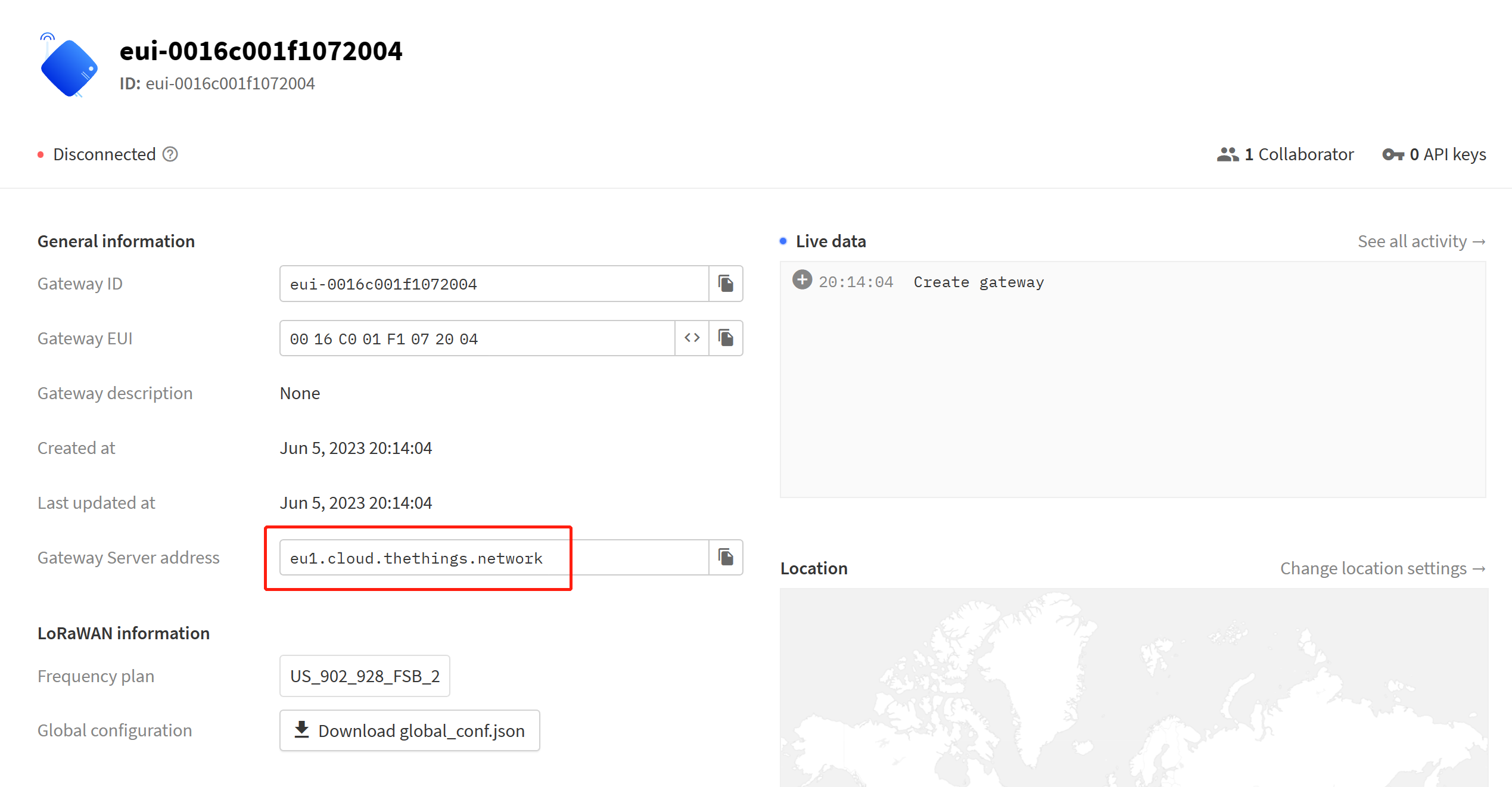
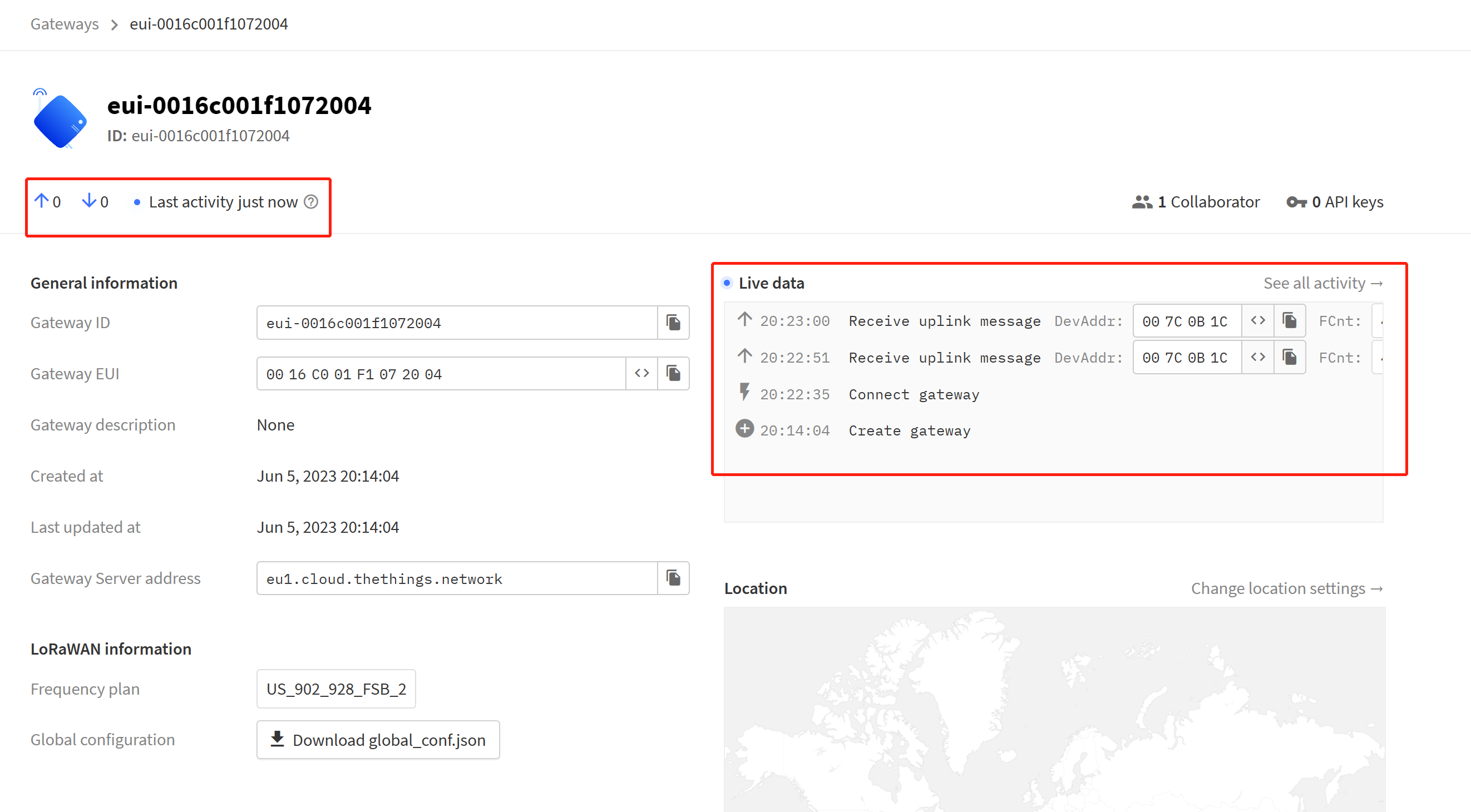
- Step 9: Make note of the Gateway Server Address on the main homepage of the gateway
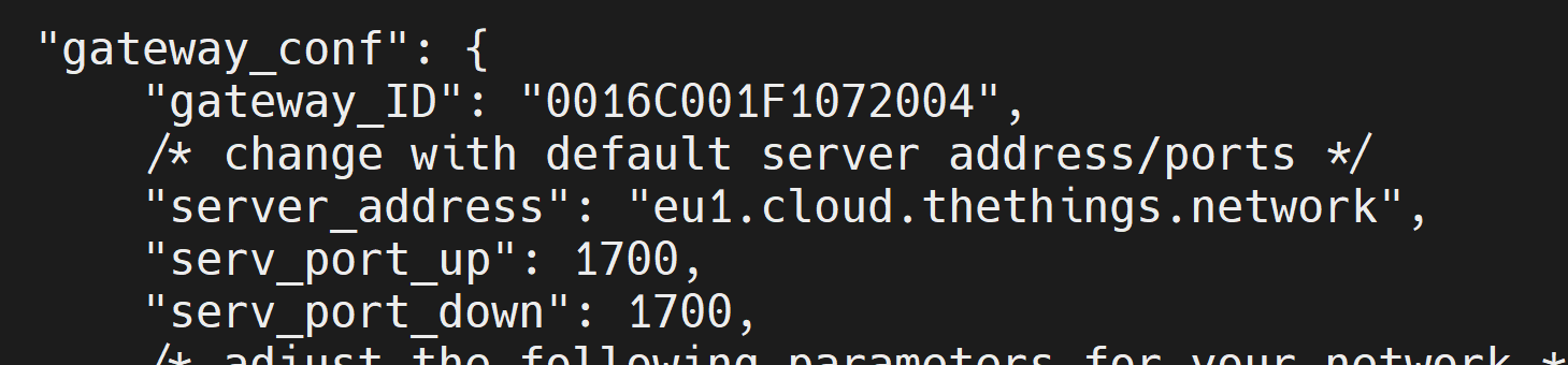
Step 9: On the reTerminal Industrial, edit the global_conf_json file that we used along with the lora_pkt_fwd command. Here you need to change the gateway_ID, server_address, serv_port_up and serv_port_down options as follows
- gateway_ID: Concentrator EUI from device
- server_address: Gateway Server Address from TTN
- serv_port_up: 1700
- serv_port_down: 1700
- Step 10: Rerun the packet forwarder
sudo ./lora_pkt_fwd -c global_conf.json.sx1250.US915
If you see the below output, that means the device has successfully connected with TTN
M.2 Key B
reServer Industrial comes with a M.2 Key B connector that supports 4G and 5G modules. Currently we have tested SIM8202G-M2 5G module
5G Module Connection Overview
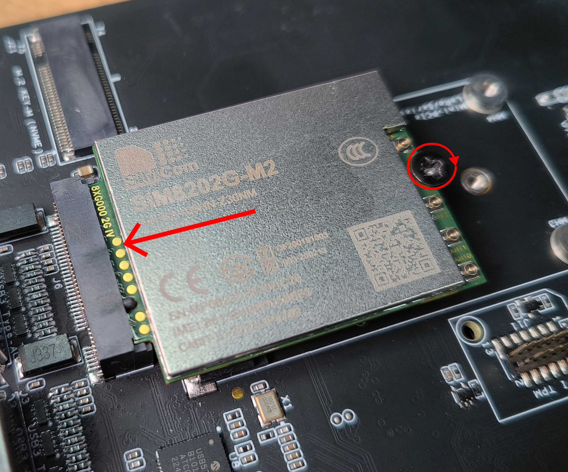
Step 1: Power off the board if it is already on
Step 2: Make sure the standoff is in place and then remove the top screw on the standoff

- Step 2: Slide in the 5G module to the M.2 Key B slot and screw in the standoff screw to secure the 5G module in place (talk about standoff)
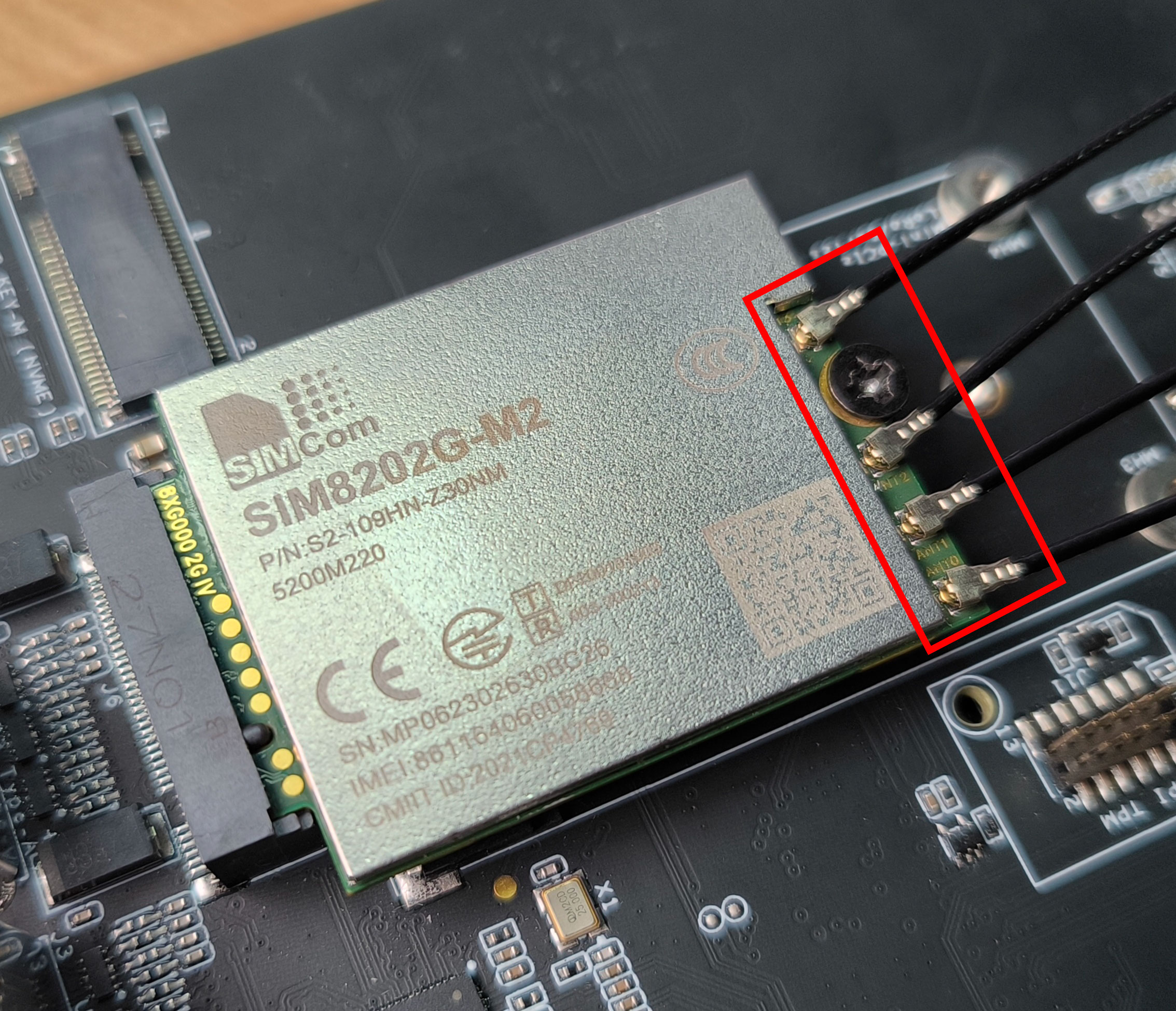
- Step 3: Connect 4 antennas to the the antenna connectors on the module. Here you need to use an IPEX 4 connector
- Step 4: Insert a 5G-enabled nano SIM card to the SIM card slot on the board making sure the gold surface of the SIM card is facing down. Here insert the card all the way in so that it will bounce back after hitting the internal spring and lock in place.
If you want to remove the SIM card, push the card in to hit the internal spring so that the SIM will come out of the slot
- Step 5: Power on the board
5G Module Usage - Test Dialing
When using the SIM8202G-M2 5G module, the module will not automatically start. So we first need to toggle a few GPIOs to make it start
- Step 1: Enter the following to start the 5G module
sudo su
cd /sys/class/gpio
echo 309 > export
cd gpio309
echo out > direction
echo 0 > value

cd..
echo 341 > export
cd PEE.02
echo out > direction
echo 1 > value

cd..
echo 330 > export
cd PCC.02
echo out > direction
echo 0 > value
Once the above is executed, LED2 will light up in green
- Step 2: Install minicom
sudo apt update
sudo apt install minicom -y
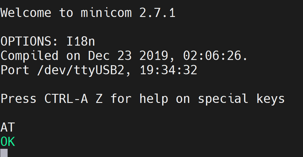
- Step 3: Enter the serial console of the connected 5G module so that we can enter AT commands and interact with the 5G module
sudo minicom -D /dev/ttyUSB2 -b 115200
- Step 4: Enter the command "AT" and press enter. If you see the response as "OK", the 5G module is working properly
- Step 6: Enter the command "ATI" to check the module information
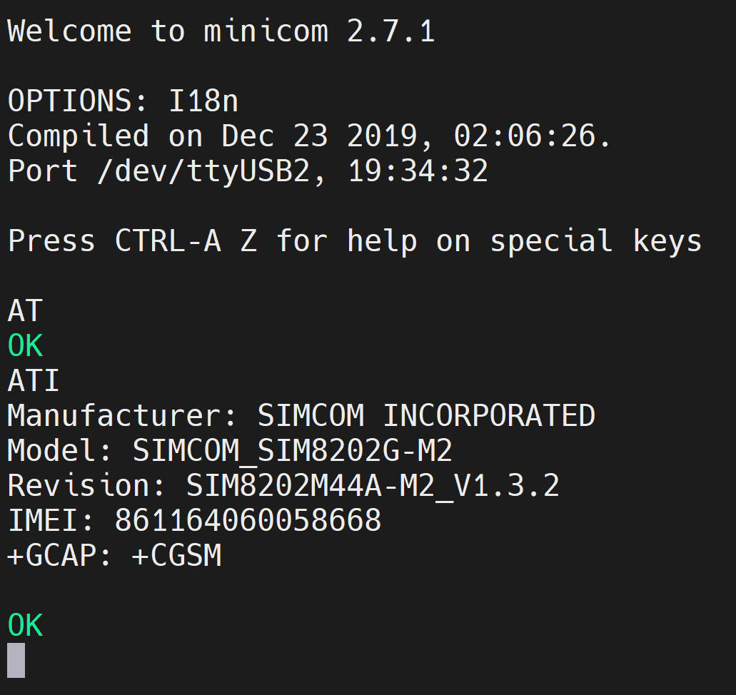
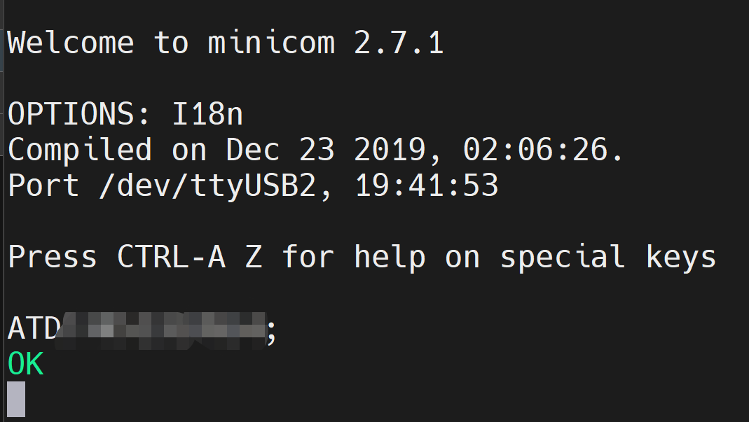
- Step 7: To test the module, enter the below command to call another phone number
ATD<phone_number>;
And you will see the below output
5G Module Usage - Connect to Internet
Coming soon
DI/ DO
reServer Industrial supports 4 digital input and 4 digital output channels, all of which are optically isolated to effectively protect the mainboard from voltage spikes or other electrical disturbances. There is also a CAN interface on this same connector which we will discuss later in this wiki
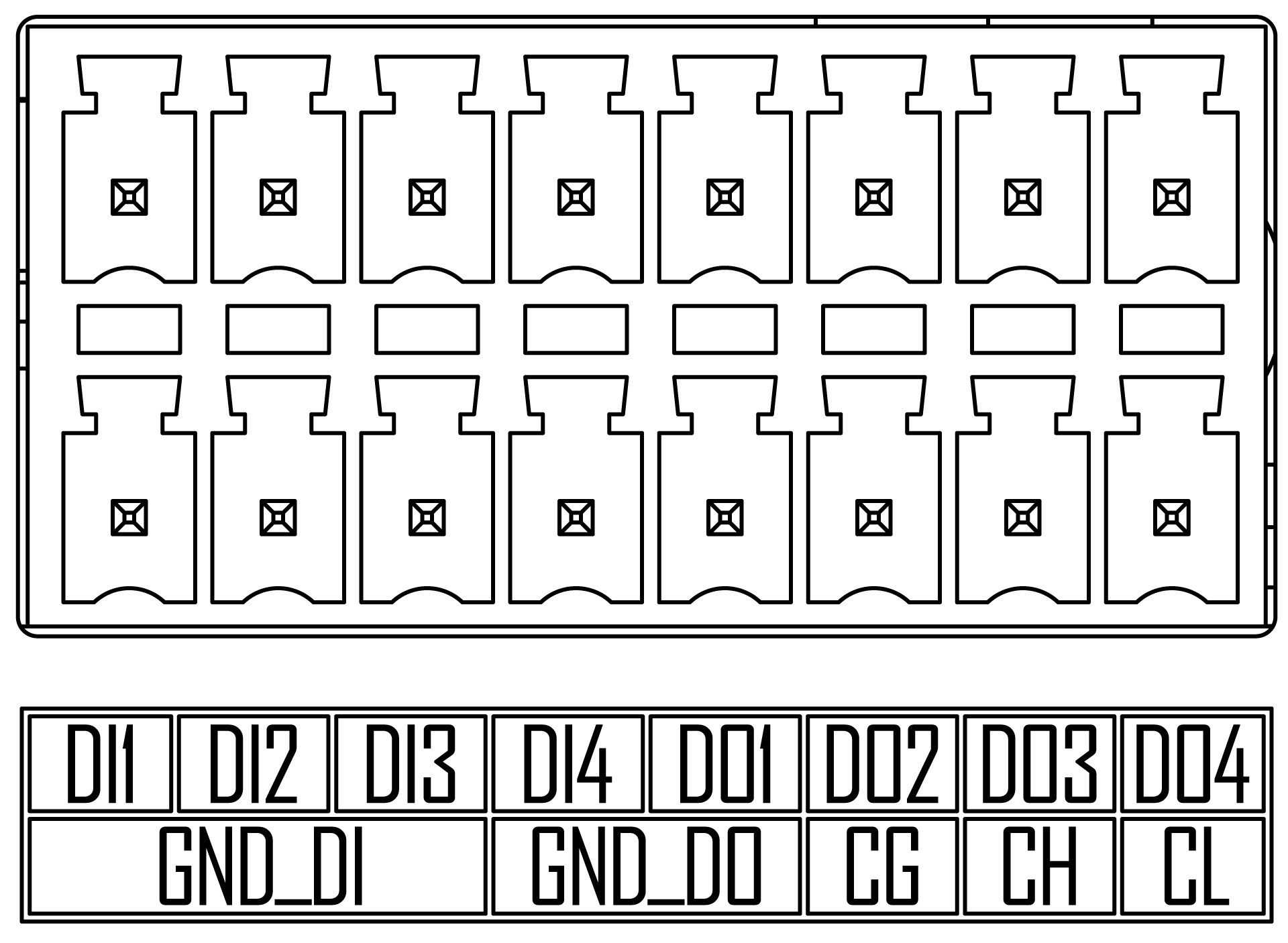
DI/ DO Pin Assignment Table
| Type | Label Name | Schematic Signal | Module Pin Number | BGA Number | GPIO Number | V/A Limits | Note |
|---|---|---|---|---|---|---|---|
| Input | DI1 | DI_1_GPIO01 | 118 | PQ.05 | 453 | 12V/ 20mA current in total | 12V Digital Input, ground signal needs to be connected to GND_DI (Pin2/4/6) |
| DI2 | DI_2_GPIO09 | 211 | PAC.06 | 492 | |||
| DI3 | DI_3_GPIO11 | 216 | PQ.06 | 454 | |||
| DI4 | DI_4_GPIO13 | 228 | PH.00 | 391 | |||
| Output | DO1 | DO_1_GPIO | 193 | PI.00 | 399 | 40V/40mA load per pin | Digital output, maximum withstand voltage 40V, ground signal needs to be connected to GND_DO(Pin8/10) |
| DO2 | DO_2_GPIO | 195 | PI.01 | 400 | |||
| DO3 | DO_3_GPIO | 197 | PI.02 | 401 | |||
| DO4 | DO_4_GPIO | 199 | PH.07 | 398 | |||
| CAN | CH | / | CAN bus with standard differential signals, ground signal needs to be connected to GND_ISO (Pin 12) | ||||
| CL | |||||||
| Ground | GND_DI | / | The reference ground signal for the 12V Digital Input, which is also the return path for the DI | ||||
| GND_DO | The reference ground signal of the digital output, which is also the return path of the DO | ||||||
| CG | The reference ground signal for CAN | ||||||
Connection Overview for DI
You can make the connection for DI by following the diagram below. It is better to add a resistor in series for the DI line. Here we have tested with a 4.7kΩ resistor connected to the DI1 pin.
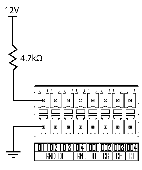
Usage for DI
You need to input a voltage of 12V on the DI line in order to get detected as an input
Step 1: Make the connetions as shown above to DI1 pin and input 12V
Step 2: Open the GPIO for DI1 as follows
sudo su
cd /sys/class/gpio
echo 453 > export
cd PQ.05
You can refer the DI/ DO Pin Assignment Table to find the GPIO number and BGA number. In the above example, for DI1 pin, GPIO number is 453 and BGA number is PQ.05
- Step 3: Execute the following to check the status
cat value
If it outputs 0, that means there is 12V input. If it outputs 1, that means there is no input voltage.
Connection Overview for DO
You can make the connection for DO by following the diagram below. It is better to add a resistor in series for the DO line. Here we have tested with a 4.7kΩ resistor
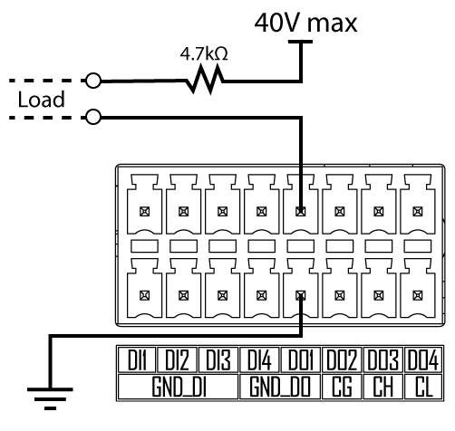
Usage for DO
Here you need to connect a load as mentioned in the above diagram. The easiest way to test this would be to connect a multimeter if you have access to one, or else connect a load that requires less than 40V maximum voltage
Step 1: Make the connetions as shown above to DO1 pin and input 40V as max
Step 2: Open the GPIO for D01 as follows
sudo su
cd /sys/class/gpio
echo 399 > export
cd PI.00
echo out > direction
You can refer the DI/ DO Pin Assignment Table to find the GPIO number and BGA number. In the above example, for DO1 pin, GPIO number is 399 and BGA number is PI.00
- Step 3: Execute the following to turn on the pin
echo 1 > value
If the load is turned on or the multimeter outputs the voltage that you have input, the test it is functioning properly.
CAN
reServer Industrial features a CAN interface that supports the CAN FD (Controller Area Network Flexible Data-Rate) protocol at 5Mbps. The CAN interface is isolated using capacitive isolation, which provides excellent EMI protection and ensures reliable communication in industrial and automation applications. A terminal resistor of 120Ω has been installed by default and you can toggle this resistor ON and OFF using GPIO.
Note: The CAN interface uses an isolated power supply, which means that the ground signal for external devices connected to the CAN interface should be connected to the CG pin
Connection Overview with USB to CAN Adapter
To test and interface with CAN bus, connect a USB to CAN adapter to the CAN connectors on the board as shown below
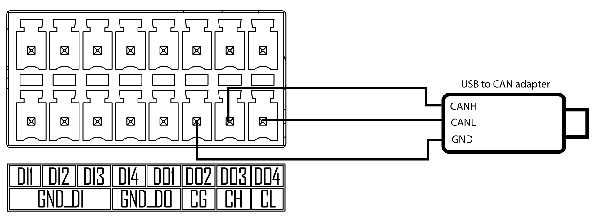
Here we have used USB to CAN Analyzer Adapter with USB Cable available on our Bazaar.
Usage with USB to CAN Adapter
Step 1: Download the driver for the USB to CAN adapter you are using from the manufacturer's website and install it. In our case, according to the adapter that we used, the drivers can be found here
Step 2: Some adapters also come with the necessary software for the PC in order to communicate with the CAN device. In our case, according to the adapter that we used, we have downloaded and installed the software which can be found here
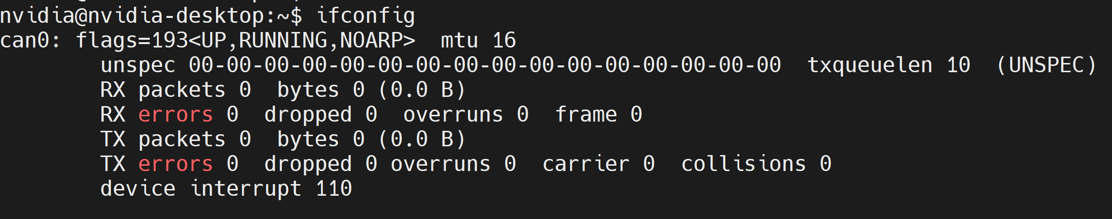
Step 3: Open a terminal window on the reServer Industrial and execute the following commands to configure and enable the CAN interface
sudo modprobe mttcan
sudo ip link set can0 type can bitrate 125000
sudo ip link set can0 up
- Step 4: Type ifconfig on the terminal and you will see the CAN interface in enabled
- Step 5: Open the CAN software that you have installed before. In this case, we will open the software that we installed according to the CAN adapter that we are using
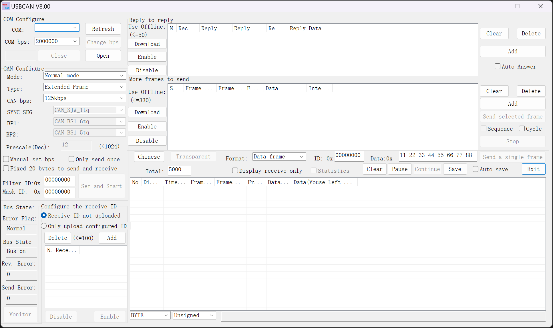
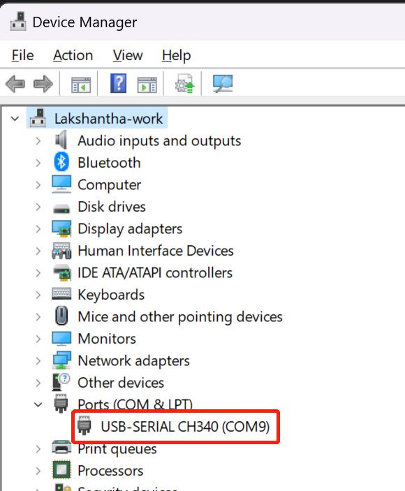
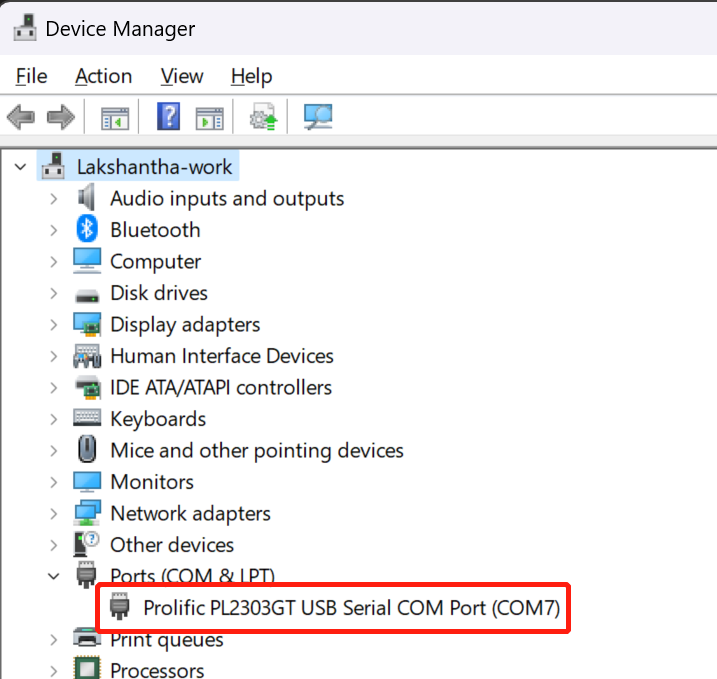
- Step 6: Connect the USB to CAN adapter to the PC and open Device Manager by searching it on windows search bar. Now you will see the connected adapter under Ports (COM & LPT). Make a note of the serial port listed here. According to the below image, the serial port is COM9
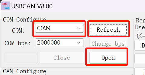
- Step 7: Open the CAN software, click Refresh next to COM section, click the drop-down-menu and select the serial port according to the connected adapter. Keep the COM bps at default and click Open
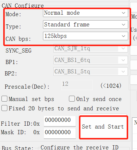
- Step 8: Keep the Mode and CAN bps at default, change the Type to Standard frame and click Set and Start
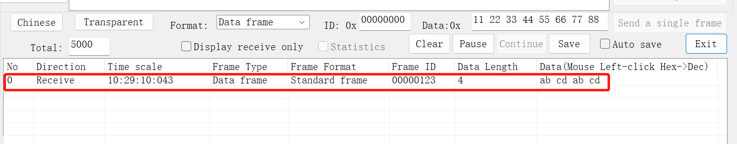
- Step 9: On reServer Industrial, execute the following command to send a CAN signal to the PC
cansend can0 123#abcdabcd
Now you will see the above signal received by the software as shown below
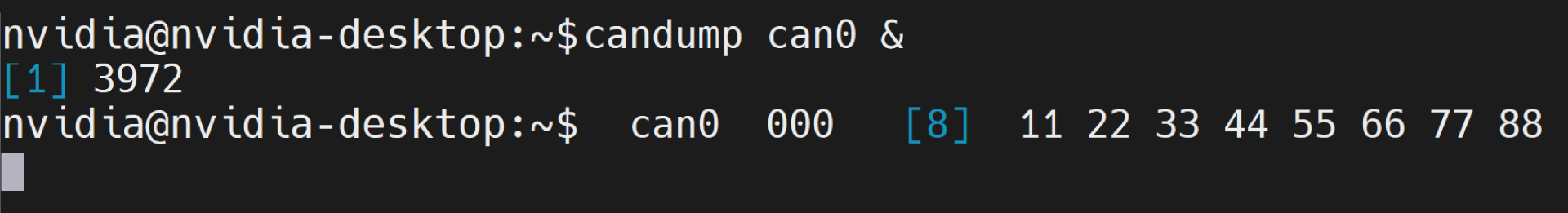
- Step 10: On reServer Industrial, execute the following command to wait for receiving CAN signals from the PC
candump can0 &
- Step 11: On the CAN software, click Send a single frame
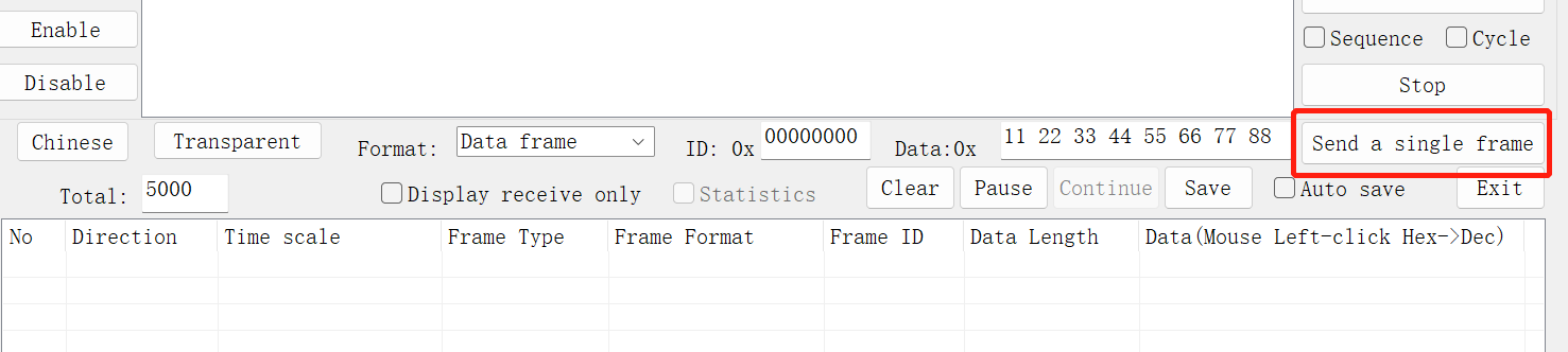
Now you will see it received by reServer Industrial as follows
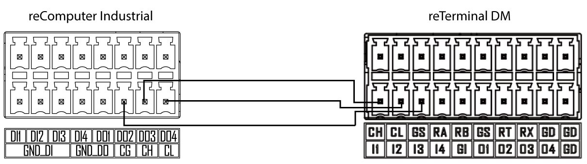
Connection Overview with reTerminal DM
If you have access to a reTerminal DM, you can communicate with it directly because reTerminal DM also has a CAN interface.
Refer to the below image to connect reServer Industrial and reTerminal DM via CAN
Usage with reTerminal DM
Step 1: Before using reTerminal DM, visit this wiki to get started with reTerminal DM
Step 2: Open a terminal window on the reServer Industrial and execute the following commands to configure and enable the CAN interface
sudo modprobe mttcan
sudo ip link set can0 type can bitrate 125000
sudo ip link set can0 up
- Step 3: Open a terminal window on the reTerminal DM and execute the following commands to configure and enable the CAN interface
sudo modprobe mttcan
sudo ip link set can0 type can bitrate 125000
sudo ip link set can0 up
- Step 4: Open a terminal window on the reTerminal DM and execute the following commands to configure and enable the CAN interface
sudo modprobe mttcan
sudo ip link set can0 type can bitrate 125000
sudo ip link set can0 up
- Step 5: If you type ifconfig on both devices, you will see the CAN interfaces are enabled
- Step 6: On the reTerminal DM, execute the following to wait for receiving CAN signals from the reServer Industrial
candump can0 &
- Step 7: On the reServer Industrial, execute the following command to send a CAN signal to the reTerminal Industrial
cansend can0 123#abcdabcd
Now you will see it received by reTerminal DM as follows
- Step 8: Repeat step 6 and step 7 but interchanging the devices. Use reTerminal DM to send CAN signals and use reServer Industrial to receive them
RS232/ RS422/ RS485 interfaces
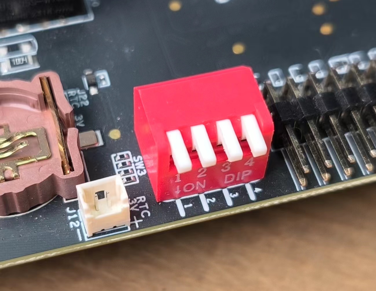
reServer Industrial has a DB9 connector which supports RS232, RS422 and RS485 communication protocols and there is a DIP switch panel onboard to switch between the different interface options
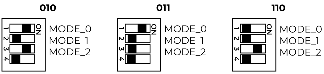
You can see the DIP switch panel as below:
And the below table explains the different modes based on the DIP switch positions
| MODE_0 | MODE_1 | MODE_2 | Mode | Status | |
|---|---|---|---|---|---|
 | 0 | 0 | 0 | RS-422 Full Duplex | 1T/1R RS-422 |
 | 0 | 0 | 1 | Pure RS-232 | 3T/5R RS-232 |
 | 0 | 1 | 0 | RS-485 Half Duplex | 1T/1R RS-485 ,TX ENABLE Low Active |
 | 0 | 1 | 1 | RS-485 Half Duplex | 1T/1R RS-485 ,TX ENABLE High Active |
 | 1 | 0 | 0 | RS-422 Full Duplex | 1T/1R RS-422 with termination resistor |
 | 1 | 0 | 1 | Pure RS-232 | 1T/1R RS-232 co-exists with RS485 |
| application without the need for the bus | |||||
| switch IC (for special usage). | |||||
 | 1 | 1 | 0 | RS-485 Half Duplex | 1T/1R RS-485 with termination resistor |
| TX ENABLE Low Active | |||||
 | 1 | 1 | 1 | Low Power | All I/O pins are High Impedance |
| Shutdown |
Out of the box, the default mode of the switches will be set to RS485 with 010 from factory
The above table takes into account the first three switches of the DIP switch panel. However, the fourth switch is responsible to toggle the slew rate which is directly related to the data rate
| Status | Note | |
|---|---|---|
 | 1 | SLEW= Vcc This RS232/RS422/RS485 Multiprotocol Transceiver limits the communication rateas follows : RS-232: MaximumData Rate is 1.5Mbps RS-485/RS-422; MaximumData Rate is 10Mbps The actual Maximum Data Rate depends on the Jetson SO Mused |
 | 0 | SLEW = GND RS-232: Maximum Data Rate is 250Kbps RS-485/RS-422: Maximum Data Rate is 250kbps |
Here we will be using USB to RS232, RS485 and RS422 adapters in order to test the interfaces. So before moving on, you need to install a serial terminal application on your PC. Here we recommend you to install Putty which is easy to setup and use.
- Step 1: Visit this website and download Putty according to your PC architecture
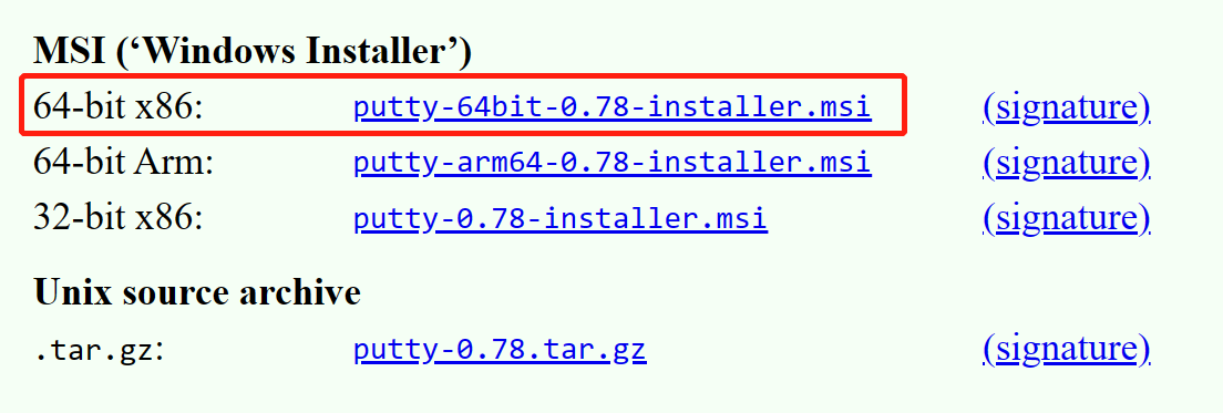
Here we have selected Putty according to the PC that we used which is a X86 windows 64-bit machine
- Step 2: Open the downloaded setup and go through the prompts to install the application
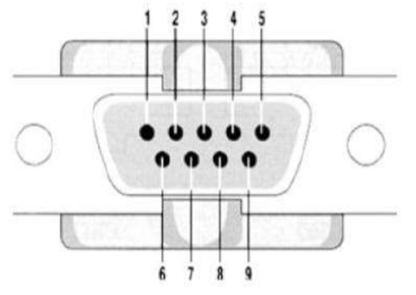
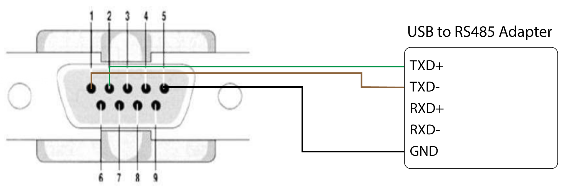
General Connection Overview
You can refer to the pin numbering of DB9 connector and the table to make the connections
| MODE | 001/101 | 000/100 | 010/011/110 |
|---|---|---|---|
| PIN | RS232 | RS422 | RS485 |
| 1 | TXD- | Data- | |
| 2 | RXD | TXD+ | Data+ |
| 3 | TXD | RXD+ | |
| 4 | RXD- | ||
| 5 | GND | GND | GND |
| 6 | |||
| 7 | RTS | ||
| 8 | CTS | ||
| 9 |
RS232 Connection Overview
Here you can use a USB to RS232 adapter to test the interface. We have used UGREEN USB to RS232 Adapter for our testing.
Step 1: Turn off the board
Step 2: Here we have 2 options to set the DIP switches. Either in 001 mode or 101 mode. The switch positions for each mode is shown below
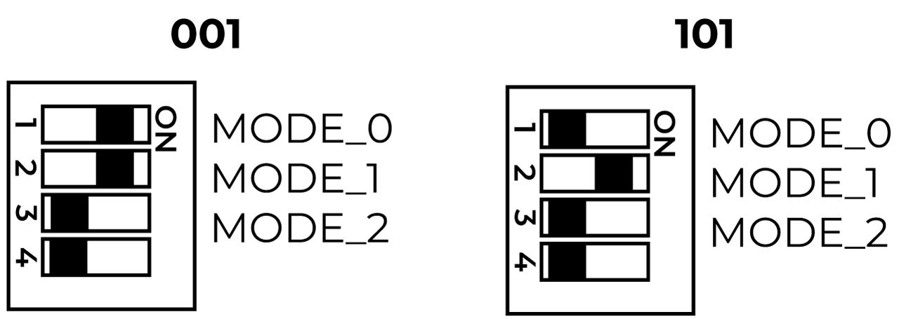
Step 3: Connect the USB to RS232 adapter to the DB9 connector
Step 4: Connect the other end to one of the USB ports on your PC
Step 5: Turn on the board
RS232 Usage
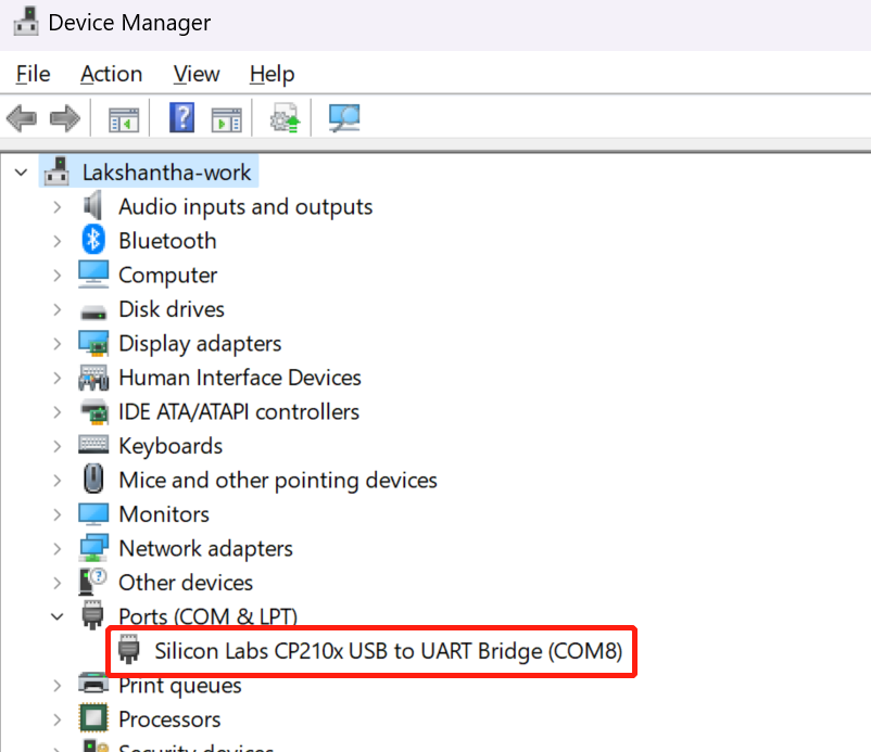
- Step 1: You may need to install a driver for the adapter that you are using or windows will automatically install the driver for you. Go to Device Manager by typing Device Manager inside windows search and check whether you can see the conenected adapter as a COM device.
Step 2: If you cannot see the adapter, you need to install the driver according to the adapter that you are using. You can generally find these drivers on the manufacturer website. For the adapter that we are using, you can this page, search for 20201 as the model number and download the driver accordingly
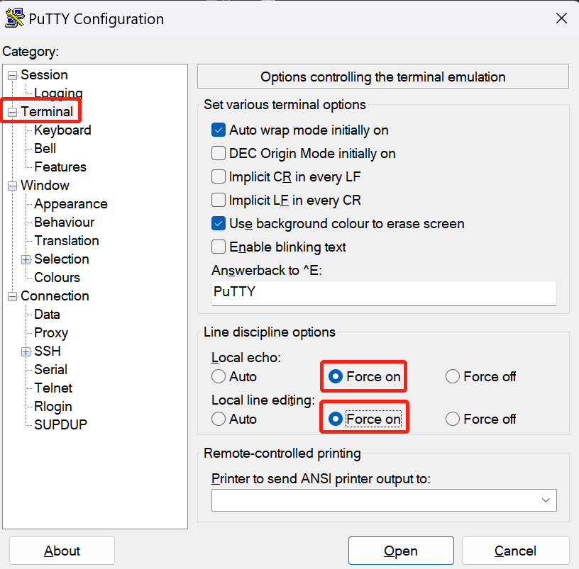
Step 3: Open Putty on the PC, select the Terminal section set the following
- Local echo: Force on
- Local line editing: Force on
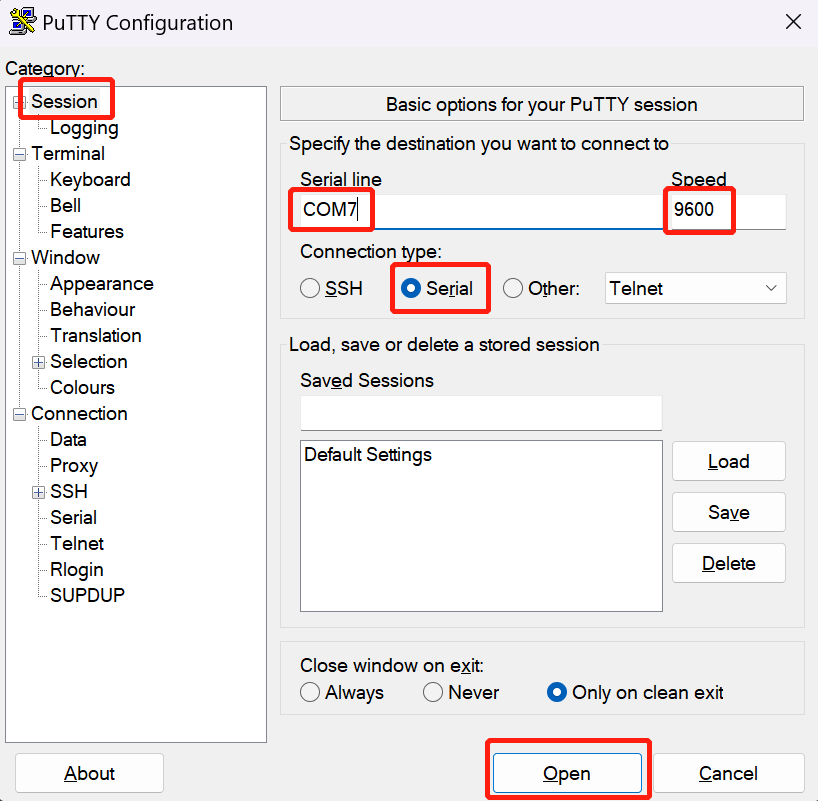
- Step 4: Select Session, under Coonection type, select Serial, set the serial port number according to what you see on Device Manager, keep the Speed as default (9600) and click Open
- Step 4: On the reServer Industrial terminal window, type the following to send a signal from the reServer Industrial to the PC
sudo chmod 777 /dev/ttyTHS0
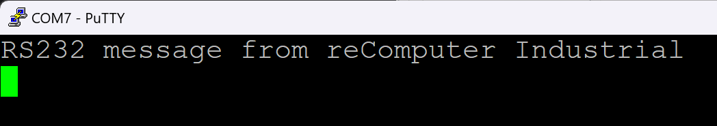
sudo echo "RS232 message from reServer Industrial" > /dev/ttyTHS0
Now you will see this message displayed on Putty
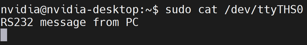
- Step 5: On the reTerminal Industrial terminal window, type the following to wait for receiving signals from the PC
sudo cat /dev/ttyTHS0
- Step 6: On Putty, type anything, press ENTER and it will be displayed on the reServer Industrial terminal window
RS422 Connection Overview
Here you can use a USB to RS422 adapter to test the interface. We have used DTech USB to RS485 Adapter for our testing.
Step 1: Turn off the board
Step 2: Here we have 2 options to set the DIP switches. Either in 000 mode or 100 mode. The switch positions for each mode is shown below
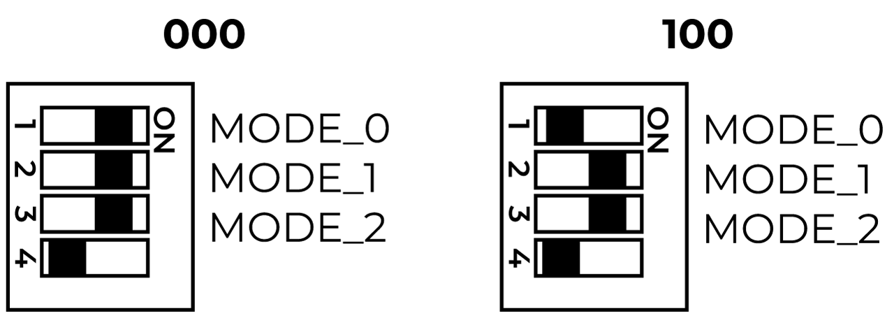
- Step 3: Connect the USB to RS422 adapter to the DB9 connector using Jumper wires as shown below. Here we have connected the adapter that we have mentioned above
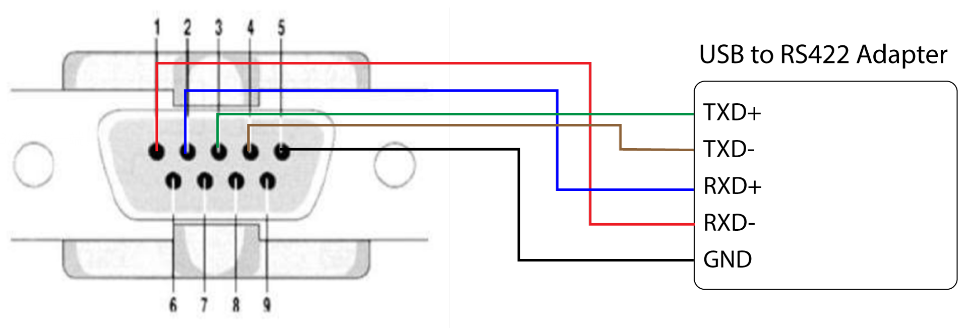
Step 4: Connect the other end to one of the USB ports on your PC
Step 5: Turn on the board
RS422 Usage
- Step 1: You may need to install a driver for the adapter that you are using or windows will automatically install the driver for you. Go to Device Manager by typing Device Manager inside windows search and check whether you can see the connected adapter as a COM device.
Step 2: If you cannot see the adapter, you need to install the driver according to the adapter that you are using. You can generally find these drivers on the manufacturer website. For the adapter that we are using, you can this page
Step 3: Open Putty on the PC, select the Terminal section set the following
- Local echo: Force on
- Local line editing: Force on
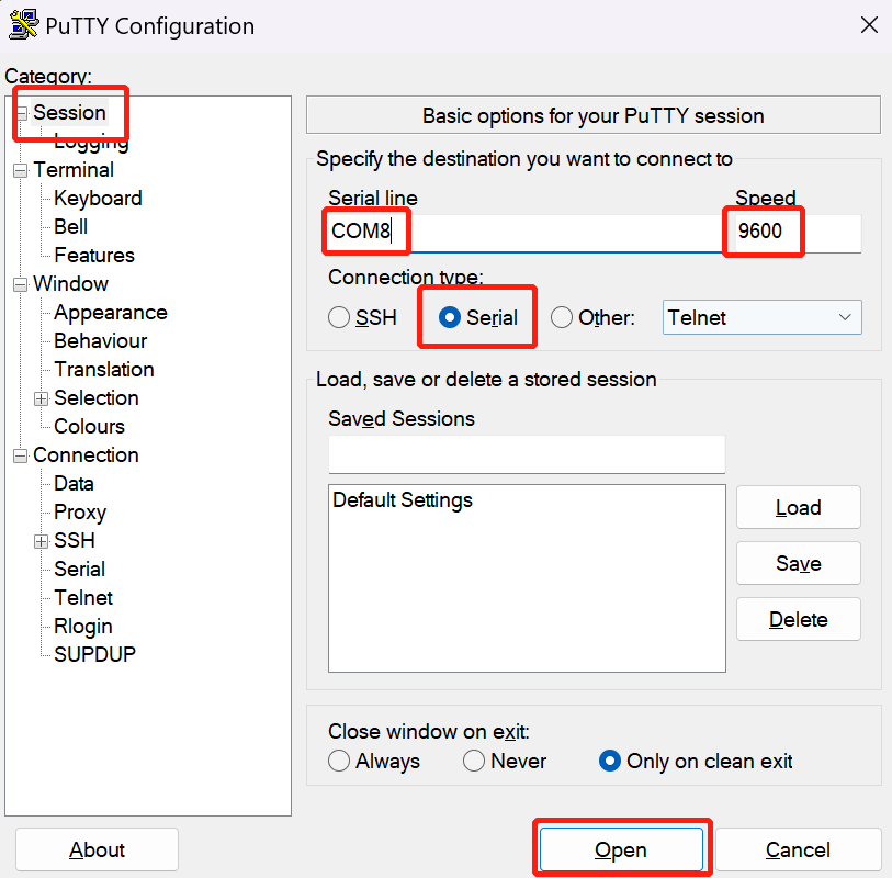
- Step 4: Select Session, under Coonection type, select Serial, set the serial port number according to what you see on Device Manager, keep the Speed as default (9600) and click Open
- Step 4: On the reServer Industrial terminal window, type the following to send a signal from the reServer Industrial to the PC
sudo chmod 777 /dev/ttyTHS0
sudo echo "RS422 message from reComputer Industrial" > /dev/ttyTHS0
Now you will see this message displayed on Putty
- Step 5: On the reTerminal Industrial terminal window, type the following to wait for receiving signals from the PC
sudo cat /dev/ttyTHS0
- Step 6: On Putty, type anything, press ENTER and it will be displayed on the reServer Industrial terminal window
RS485 Connection Overview
Here you can use a USB to RS422 adapter to test the interface. We have used DTech USB to RS485 Adapter for our testing.
Step 1: Turn off the board
Step 2: Here we have 3 options to set the DIP switches. Either in 010 mode or 011 mode or 110 mode. The switch positions for each mode is shown below
- Step 3: Connect the USB to RS422 adapter to the DB9 connector using Jumper wires as shown below. Here we have connected the adapter that we have mentioned above
Step 4: Connect the other end to one of the USB ports on your PC
Step 5: Turn on the board
RS485 Usage
- Step 1: You may need to install a driver for the adapter that you are using or windows will automatically install the driver for you. Go to Device Manager by typing Device Manager inside windows search and check whether you can see the conenected adapter as a COM device.
Step 2: If you cannot see the adapter, you need to install the driver according to the adapter that you are using. You can generally find these drivers on the manufacturer website. For the adapter that we are using, you can this page
Step 3: Open Putty on the PC, select the Terminal section set the following
- Local echo: Force on
- Local line editing: Force on
- Step 4: Select Session, under Coonection type, select Serial, set the serial port number according to what you see on Device Manager, keep the Speed as default (9600) and click Open
- Step 4: On the reServer Industrial terminal window, type the following to send a signal from the reServer Industrial to the PC
sudo su
cd /sys/class/gpio
echo 460 > export
cd PR.04
echo out > direction
echo 0 > value
echo "RS485 message from reServer Industrial" > /dev/ttyTHS0
Now you will see this message displayed on Putty
- Step 5: On the reTerminal Industrial terminal window, type the following to wait for receiving signals from the PC
sudo su
cd /sys/class/gpio
echo 460 > export
cd PR.04
echo out > direction
echo 1 > value
cat /dev/ttyTHS0
- Step 6: On Putty, type anything, press ENTER and it will be displayed on the reServer Industrial terminal window
USB
reServer Industrial comes with 3x USB3.2 connectors onboard and has the following features:
- On the dual stacked USB connectors, the upper and lower USB ports share a current-limiting IC, with a total power supply capacity of 2.1A maximum output current (single can also be 2.1A). If over 2.1A, it will enter the over-current protection state.
- On the single USB connector next to the dual stacked USB connectors, it has a total power supply capacity of 2.1A maximum output current. If over 2.1A, it will enter the over-current protection state.
- Orin NX module comes with 3 USB3.2, only one of which is used in reServer Industrial and converted to 3 ways. (USB3.1 TYPE-A x2 - J4 and USB3.1 TYPE-A x1 -J3).
- Only supports USB Host, not Device mode
- Provide 5V 2.1A
- Hot-swappable
Usage
We will explain how to do a simple benchmark on a connected USB flash drive
- Step 1: Check the write speed by executing the below command
sudo dd if=/dev/zero of=/dev/$1 bs=100M count=10 conv=fdatasync
- Step 2: Check the read speed by executing the below commands. Make sure to execute this after executing the above command for write speed.
sudo sh -c "sync && echo 3 > /proc/sys/vm/drop_caches"
sudo dd if=/dev/$1 of=/dev/null bs=100M count=10
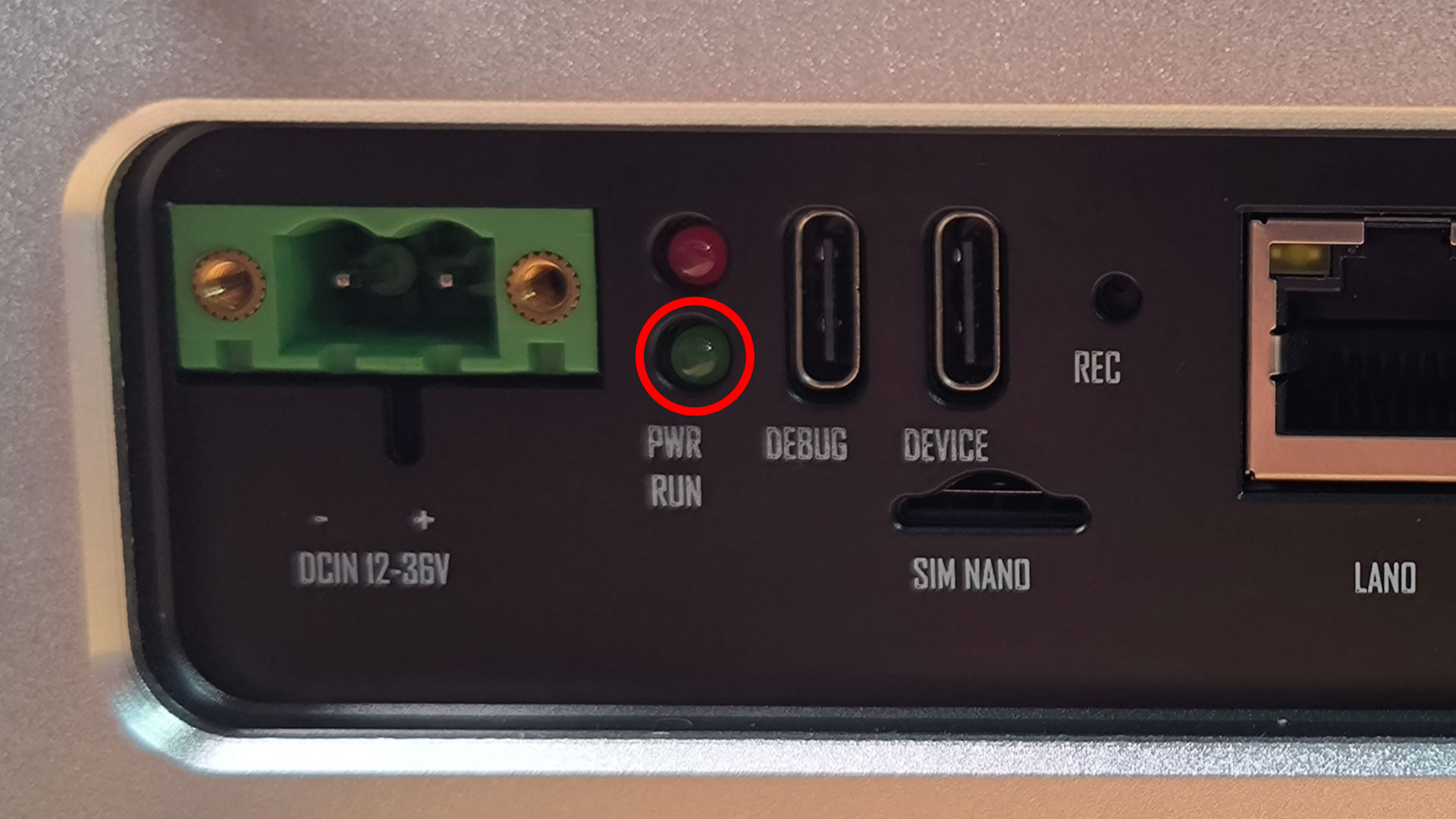
Configurable LED
There is a Green color LED located on the board as shown below. By default it is acting as the LED which shows the device is running properly. However, you can program this LED to turn ON and OFF by the system as well
Usage
- Step 1: Enter the following commands on a terminal window to access the Green color LED
sudo -i
cd /sys/class/gpio
echo 329 > export
cd PCC.01
echo out > direction
- Step 2: Turn OFF the LED
echo 0 > value
- Step 3: Turn ON the LED
echo 1 > value
If you have finished using the LED, you can execute the following
cd ..
echo 329 > unexport
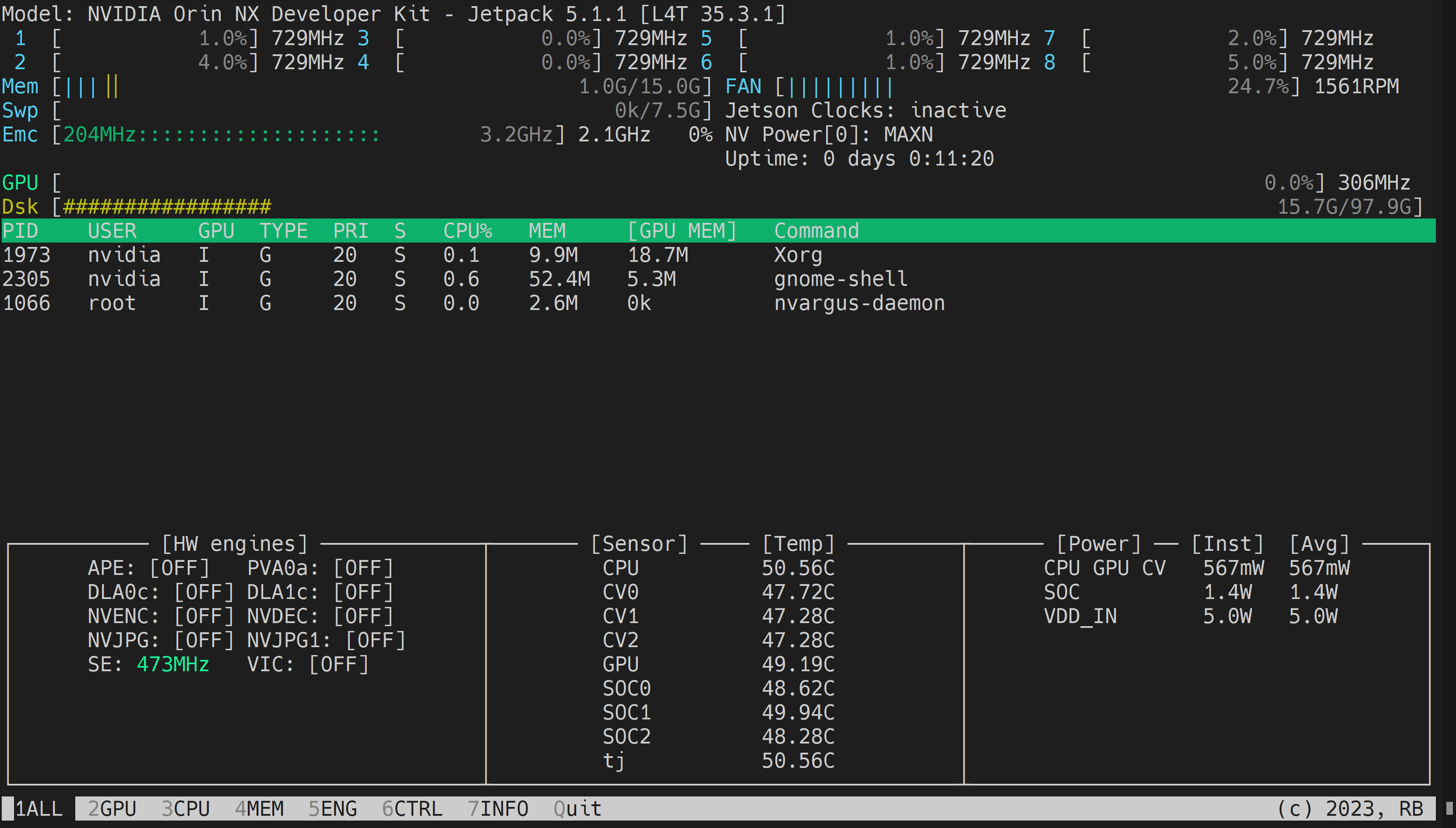
Monitor System Performance
We can use jetson stats application to monitor the temperatures of the system components and check other system details such as
View CPU, GPU, RAM utilizations
Change power modes
Set to max clocks
Check JetPack information
Step 1: On the reServer Industrial terminal windows, type the following
sudo apt update
sudo apt install python3-pip -y
sudo pip3 install jetson-stats
- Step 2: Reboot the board
sudo reboot
- Step 3: Type the following on the terminal
jtop
Now jtop application will open as follows
- Step 4: Here you can cycle through the different pages of the applications and explore all the features!
TPM
reServer Industrial comes with a TPM interface to connect an external TPM module. Here we have tested with a Infineon SLB9670 based TPM2.0 Module.
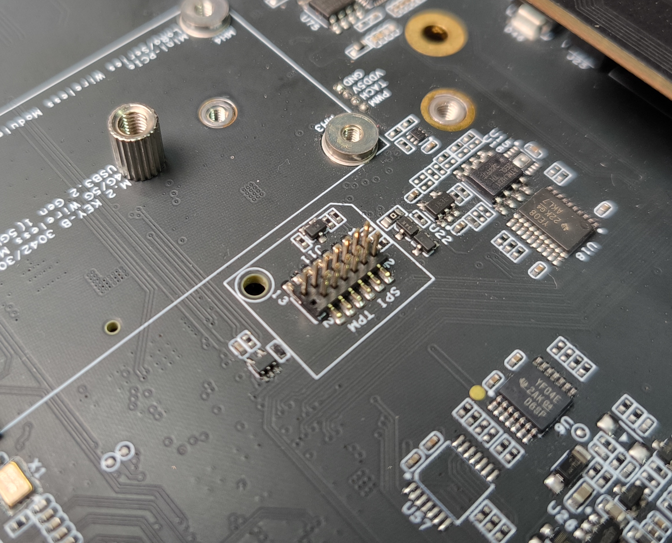
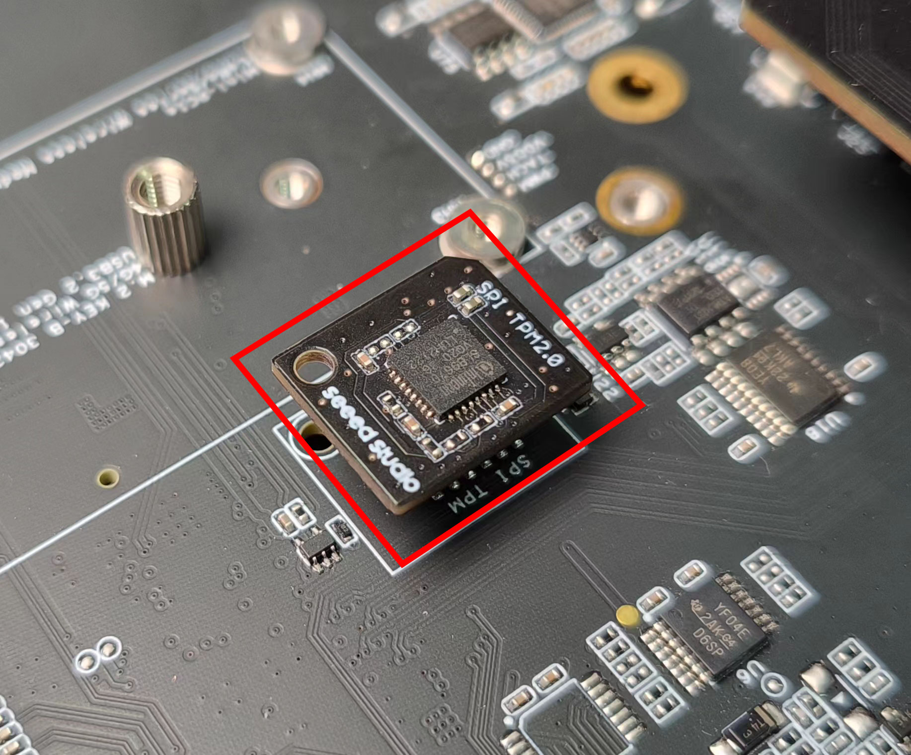
Connection Overview
Connect the TPM module to the TPM connector as shown below
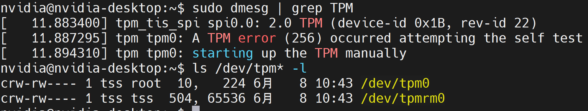
Usage
Check whether the TPM module is loaded properly by executing the below commands
sudo dmesg | grep TPM
ls /dev/tpm* -l
And you will see the output as follows
Max Performance on reServer Industrial
If you want to enable maximum performance on the reServer Industrial, please follow the below instructions
- Step 1: Enter the below command to enable the maximum power mode
sudo nvpmodel -m 0
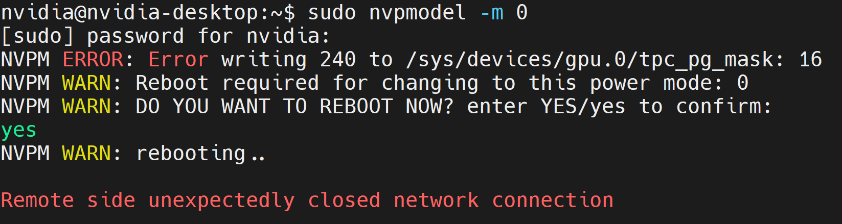
Here it will ask to type YES in order to reboot the board
- Step 2: Once the board is booted, enter the following command to set the CPU clocks to the maximum frequency
sudo jetson_clocks
GPIO Table
You can access the GPIO table of the reServer Industrial to get familiar with all the pin mappings.
Execute the following inside a terminal to access it
sudo cat /sys/kernel/debug/gpio
And you will see the output as follows
gpiochip2: GPIOs 300-315, parent: i2c/1-0021, 1-0021, can sleep:
 gpio-300 (wl_dis              |gpio_xten_pin@0     ) out hi
 gpio-301 (hst_wake_wl         |gpio_xten_pin@1     ) out hi
 gpio-302 (wl_wake_hst         |gpio_xten_pin@2     ) out hi ACTIVE LOW
 gpio-303 (bt_dis              |gpio_xten_pin@3     ) out hi
 gpio-304 (hst_wake_bt         )
 gpio-305 (bt_wake_hst         )
 gpio-306 (spi0_rst_3v3        |gpio_xten_pin@6     ) out lo ACTIVE LOW
 gpio-307 (gpio_pin7           |gpio_xten_pin@7     ) out lo ACTIVE LOW
 gpio-308 (can_120R_en         )
 gpio-309 (M2B_PCIe_rst        )
 gpio-310 (USB_HUB_rst         |gpio_xten_pin@10    ) out hi
 gpio-311 (PCIe_ETH_rst        )
 gpio-312 (M2B_WOWWAN          )
 gpio-313 (M2B_DPR_3V3         )
 gpio-314 (SIM_MUX_SEL         )
 gpio-315 (gpio_pin15          )

gpiochip1: GPIOs 316-347, parent: platform/c2f0000.gpio, tegra234-gpio-aon:
 gpio-316 (PAA.00              )
 gpio-317 (PAA.01              )
 gpio-318 (PAA.02              )
 gpio-319 (PAA.03              )
 gpio-320 (PAA.04              )
 gpio-321 (PAA.05              |fixed-regulators:reg) out hi
 gpio-322 (PAA.06              )
 gpio-323 (PAA.07              )
 gpio-324 (PBB.00              )
 gpio-325 (PBB.01              )
 gpio-326 (PBB.02              )
 gpio-327 (PBB.03              )
 gpio-328 (PCC.00              )
 gpio-329 (PCC.01              )
 gpio-330 (PCC.02              )
 gpio-331 (PCC.03              |mux                 ) out hi
 gpio-332 (PCC.04              )
 gpio-333 (PCC.05              )
 gpio-334 (PCC.06              )
 gpio-335 (PCC.07              )
 gpio-336 (PDD.00              )
 gpio-337 (PDD.01              )
 gpio-338 (PDD.02              )
 gpio-339 (PEE.00              )
 gpio-340 (PEE.01              )
 gpio-341 (PEE.02              )
 gpio-342 (PEE.03              )
 gpio-343 (PEE.04              |power-key           ) in  hi IRQ ACTIVE LOW
 gpio-344 (PEE.05              )
 gpio-345 (PEE.06              )
 gpio-346 (PEE.07              )
 gpio-347 (PGG.00              )
gpiochip0: GPIOs 348-511, parent: platform/2200000.gpio, tegra234-gpio:
 gpio-348 (PA.00               |fixed-regulators:reg) out lo
 gpio-349 (PA.01               )
 gpio-350 (PA.02               )
 gpio-351 (PA.03               )
 gpio-352 (PA.04               )
 gpio-353 (PA.05               )
 gpio-354 (PA.06               )
 gpio-355 (PA.07               )
 gpio-356 (PB.00               )
 gpio-357 (PC.00               )
 gpio-358 (PC.01               )
 gpio-359 (PC.02               )
 gpio-360 (PC.03               )
 gpio-361 (PC.04               )
 gpio-362 (PC.05               )
 gpio-363 (PC.06               )
 gpio-364 (PC.07               )
 gpio-365 (PD.00               )
 gpio-366 (PD.01               )
 gpio-367 (PD.02               )
 gpio-368 (PD.03               )
 gpio-369 (PE.00               )
 gpio-370 (PE.01               )
 gpio-371 (PE.02               )
 gpio-372 (PE.03               )
 gpio-373 (PE.04               )
 gpio-374 (PE.05               )
 gpio-375 (PE.06               )
 gpio-376 (PE.07               )
 gpio-377 (PF.00               )
 gpio-378 (PF.01               )
 gpio-379 (PF.02               )
 gpio-380 (PF.03               )
 gpio-381 (PF.04               )
 gpio-382 (PF.05               )
 gpio-383 (PG.00               |force-recovery      ) in  hi IRQ ACTIVE LOW
 gpio-384 (PG.01               )
 gpio-385 (PG.02               )
 gpio-386 (PG.03               )
 gpio-387 (PG.04               )
 gpio-388 (PG.05               )
 gpio-389 (PG.06               )
 gpio-390 (PG.07               |cd                  ) in  lo IRQ
 gpio-391 (PH.00               )
 gpio-392 (PH.01               )
 gpio-393 (PH.02               )
 gpio-394 (PH.03               )
 gpio-395 (PH.04               )
 gpio-396 (PH.05               )
 gpio-397 (PH.06               )
 gpio-398 (PH.07               )
 gpio-399 (PI.00               )
 gpio-400 (PI.01               )
 gpio-401 (PI.02               )
 gpio-402 (PI.03               )
 gpio-403 (PI.04               )
 gpio-404 (PI.05               )
 gpio-405 (PI.06               )
 gpio-406 (PJ.00               )
 gpio-407 (PJ.01               )
 gpio-408 (PJ.02               )
 gpio-409 (PJ.03               )
 gpio-410 (PJ.04               )
 gpio-411 (PJ.05               )
 gpio-412 (PK.00               )
 gpio-413 (PK.01               )
 gpio-414 (PK.02               )
 gpio-415 (PK.03               )
 gpio-416 (PK.04               )
 gpio-417 (PK.05               )
 gpio-418 (PK.06               )
 gpio-419 (PK.07               )
 gpio-420 (PL.00               )
 gpio-421 (PL.01               )
 gpio-422 (PL.02               |nvidia,pex-wake     ) in  hi ACTIVE LOW
 gpio-423 (PL.03               )
 gpio-424 (PM.00               )
 gpio-425 (PM.01               )
 gpio-426 (PM.02               )
 gpio-427 (PM.03               )
 gpio-428 (PM.04               )
 gpio-429 (PM.05               )
 gpio-430 (PM.06               )
 gpio-431 (PM.07               )
 gpio-432 (PN.00               )
 gpio-433 (PN.01               )
 gpio-434 (PN.02               )
 gpio-435 (PN.03               )
 gpio-436 (PN.04               )
 gpio-437 (PN.05               )
 gpio-438 (PN.06               )
 gpio-439 (PN.07               )
 gpio-440 (PP.00               )
 gpio-441 (PP.01               )
 gpio-442 (PP.02               )
 gpio-443 (PP.03               )
 gpio-444 (PP.04               )
 gpio-445 (PP.05               )
 gpio-446 (PP.06               )
 gpio-447 (PP.07               )
 gpio-448 (PQ.00               )
 gpio-449 (PQ.01               )
 gpio-450 (PQ.02               )
 gpio-451 (PQ.03               )
 gpio-452 (PQ.04               )
 gpio-453 (PQ.05               )
 gpio-454 (PQ.06               )
 gpio-455 (PQ.07               )
 gpio-456 (PR.00               )
 gpio-457 (PR.01               )
 gpio-458 (PR.02               )
 gpio-459 (PR.03               )
 gpio-460 (PR.04               )
 gpio-461 (PR.05               )
 gpio-462 (PX.00               )
 gpio-463 (PX.01               )
 gpio-464 (PX.02               )
 gpio-465 (PX.03               )
 gpio-466 (PX.04               )
 gpio-467 (PX.05               )
 gpio-468 (PX.06               )
 gpio-469 (PX.07               )
 gpio-470 (PY.00               )
 gpio-471 (PY.01               )
 gpio-472 (PY.02               )
 gpio-473 (PY.03               )
 gpio-474 (PY.04               )
 gpio-475 (PY.05               )
 gpio-476 (PY.06               )
 gpio-477 (PY.07               )
 gpio-478 (PZ.00               )
 gpio-479 (PZ.01               |vbus                ) in  hi IRQ ACTIVE LOW
 gpio-480 (PZ.02               )
 gpio-481 (PZ.03               )
 gpio-482 (PZ.04               )
 gpio-483 (PZ.05               )
 gpio-484 (PZ.06               |cs_gpio             ) out lo
 gpio-485 (PZ.07               )
 gpio-486 (PAC.00              )
 gpio-487 (PAC.01              )
 gpio-488 (PAC.02              )
 gpio-489 (PAC.03              )
 gpio-490 (PAC.04              )
 gpio-491 (PAC.05              )
 gpio-492 (PAC.06              )
 gpio-493 (PAC.07              )
 gpio-494 (PAD.00              )
 gpio-495 (PAD.01              )
 gpio-496 (PAD.02              )
 gpio-497 (PAD.03              )
 gpio-498 (PAE.00              )
 gpio-499 (PAE.01              )
 gpio-500 (PAF.00              )
 gpio-501 (PAF.01              )
 gpio-502 (PAF.02              )
 gpio-503 (PAF.03              )
 gpio-504 (PAG.00              )
 gpio-505 (PAG.01              )
 gpio-506 (PAG.02              )
 gpio-507 (PAG.03              )
 gpio-508 (PAG.04              )
 gpio-509 (PAG.05              )
 gpio-510 (PAG.06              )
 gpio-511 (PAG.07              )
Resources
(change the links)
- reServer Industrial Datasheet
- reServer Industrial Reference Guide
- NVIDIA Jetson Devices and Carrier Boards Comparison
- reServer Industrial 3D File
Tech Support
Please do not hesitate to submit issues into our forum.