Arch Mix

Arch Mix is a thin, lightweight development board based on NXP i.MX RT1052 processor(3020 CoreMark/1284 DMIPS @ 600 MHz). Which makes it suitable for industrial control, especially for scenes with large code and high real-time application requirements.
The i.MX RT1052 is a new processor family featuring NXP’s advanced implementation of the Arm Cortex®-M7 core. Currently, the i.MX RT1052 is the highest performing Cortex-M7 solution delivering 3036 CoreMarks, which is 13 times better than the LPC1788 microcontroller. In addition to the high-speed performance it provides fast real-time responsiveness. The i.MX RT1050 also has rich audio and video features, including LCD display, basic 2D graphics, camera interface, SPDIF, and I2S audio interface.

The Initial Firmware of Arch Mix is RT-Thread which is depreciated, please follow this wiki to flash the Arduino Bootloader into Arch Mix and use it as Arduino Dev board.
Application Ideas
- Industrial Control
- Smart Building
- Industrial Human Machine Interfaces
- Automation & Process Control
- Robot
Feature
- ARM® Cortex®-M7 600MHz microcontroller(NXP i.MX RT1052)
- Ultra-fast system loading speed
- Rich peripheral interface: RMII, CAN, I2C, UART, CSI, I2S, ADC, SPDIF IN/OUT, SWD
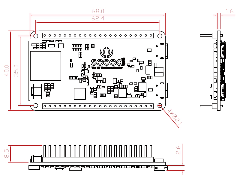
- Smaller than other Demo boards of RT1052/1050: 67mm x 39mm
Specification
| Parameters | Value |
|---|---|
| Processor: NXP i.MX RT1052 | |
| Platform | ARM Cortex-M7 MPCore |
| Frequency | 600 MHz |
| Boot ROM | 96KB |
| ON-Chip RAM | 512KB |
| Memory | |
| SDRAM | 32MB |
| QSPI Flash | 8MB |
| HyperFlash(Optional) | 64MB |
| Connectivity | |
| USB 2.0 Host | x1 |
| USB 2.0 OTG, and DC 5V Power In | x1 |
| Boot configuration DIP switch | x1 |
| LED | Power LED x1 User RGB LED x1 |
| Buttons | Reset button x1, On/Off button x1, User button x1 |
| 24bit RGB LCD interface | x1 |
| Micro SD card connector | x1 |
| RTC 3V battery connector | x1 |
| 22Pin header | RMII, CAN, I2C, UART, CSI, I2S, ADC, SPDIF IN/OUT, SWD |
Hardware Overview


*1 We provide two options for the flash, you can use 64M HyperFlash(U7-default DNP) or 8M QSPI Flash(U11-default selection).
*2 After the board is powered by USB OTG, you can switch the system on and off by pressing and holding(about 3~5 seconds) this button.
*3 Please note that this port is a 1.25mm CR2032 Battery port, do not plug in a Li-Po battery. If you want to use the RTC function, you can search the ‘CR2032 Battery with Wire Leads’ in the Amazon or other web.
Power
Please supply power through the Micro-USB OTG port.
- The input power supply voltage is 5V, can not exceed 5.5V.
- All digital and analog IO interface levels are 3.3V. Please do not input more than 3.3V, otherwise the CPU may be damaged.
- RTC's battery-powered interface(J6) can only be connected to a button battery of about 3V, and the voltage cannot exceed 3.6V.
Switch
The Arch Mix can be configured into three different boot modes: HyperFlash, QSPI Flash and SD Card. We use QSPI Flash by default, when you change the boot mode, you need to change the DIP switch to the corresponding position.
| DEVICE | BOOT_CFG | SW1 four keys value |
|---|---|---|
| HyperFlash | 0x02_00 | 0 , 1 , 1 , 0 |
| QSPI Flash | 0x00_00 | 0 , 0 , 1 , 0 |
| SD | 0x00_40 | 1 , 0 , 1 , 0 |
Button
There are three buttons on this board, please check the function table.
| Name | Function | Detail |
|---|---|---|
| SW2 | User Button | For user configure, for this development board No. 125 pin is SW2 |
| SW3 | RESET | System reset, when you press this button the system will restart |
| SW4 | Power On/OFF | Switch the system on and off by pressing and holding(about 3~5 seconds) this button |
LCD Interface
As you can see, there is a 50 pin LCD Interface on this board, it Support up to 1366 x 768 WXGA resolution. In case you need a LCD screen for this board, you can use the LCD8000 serial screen. Check the links below.
Pinout
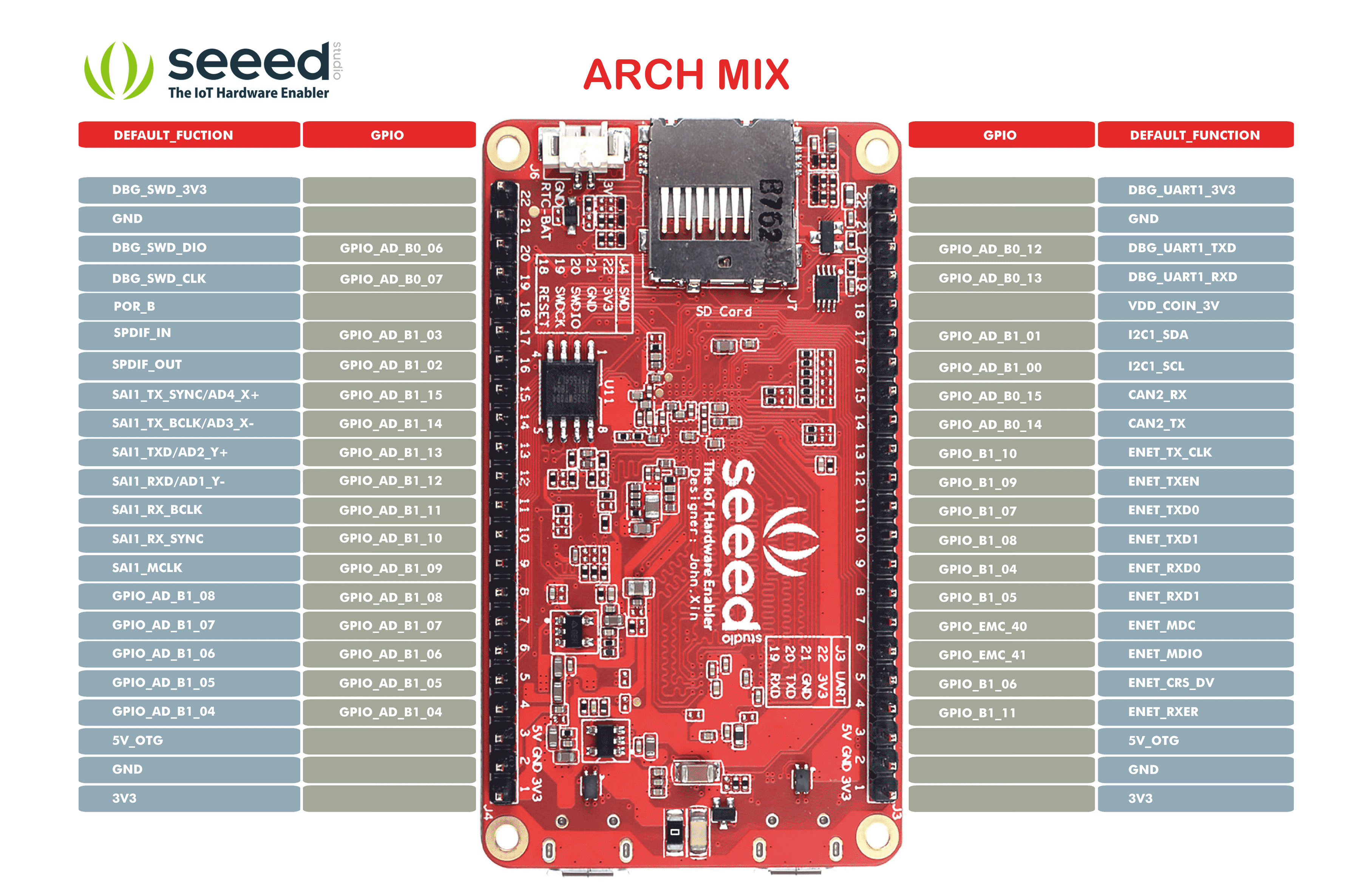
Most of the pins of NXP i.MX RT1050 processor have multiplexing function, you can click the attachment below to view the detailed pin multiplexing.
Blcok Diagram

Dimension Diagram

Flashing Arduino Bootloader to Arch Mix
You can now flash the Arduino bootloader to the Arch Mix and use it like a Arduino board! This may be one the of most powerful (Cortex M7) Arduino board in the market.
Switch Settings
Make sure it is running from the QSPI where switches are in order:
- 0010
Hardware Required
Arch Mix x 1
J-Link Debug Probes x 1
Getting Started
Download and install the J-Flash software from the official site according to your PC's OS.
Find the installed path of J-Flash and make the following changes.
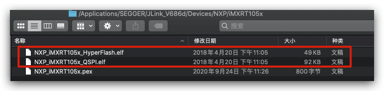
Navigate the installed location:
SEGGER/JLink_V686/Devices/NXP/iMXRT105x.
For example, for macOS, my installed path is :
/Applications/SEGGER/JLink_V686/Devices/NXP/iMXRT105x
- Download and unzip the iMXRT105x.zip, paste and replace the files into this path.
- Navigate back to the root location of
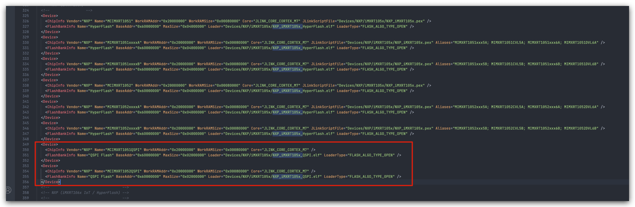
SEGGER/JLink_V686and there should be a file namedJLinkDevices.xml. Open the file with editor and searchNXP_iMXRT105x_and you should see there are some options. Copy and paste the following code to the same section as indicated in the diagram:
  <Device>
    <ChipInfo Vendor="NXP" Name="MCIMXRT1051QSPI" WorkRAMAddr="0x20000000" WorkRAMSize="0x00080000" Core="JLINK_CORE_CORTEX_M7" />
    <FlashBankInfo Name="QSPI Flash" BaseAddr="0x60000000" MaxSize="0x02000000" Loader="Devices/NXP/iMXRT105x/NXP_iMXRT105x_QSPI.elf" LoaderType="FLASH_ALGO_TYPE_OPEN" />
  </Device>
  <Device>
    <ChipInfo Vendor="NXP" Name="MCIMXRT1052QSPI" WorkRAMAddr="0x20000000" WorkRAMSize="0x00080000" Core="JLINK_CORE_CORTEX_M7" />
    <FlashBankInfo Name="QSPI Flash" BaseAddr="0x60000000" MaxSize="0x02000000" Loader="Devices/NXP/iMXRT105x/NXP_iMXRT105x_QSPI.elf" LoaderType="FLASH_ALGO_TYPE_OPEN" />
  </Device>
Save the file.
Now the JFlash is configured and you can open the J-Flash Software.
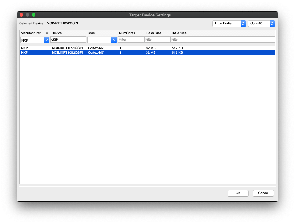
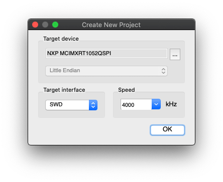
Create a new J-Flash project and Select the MCIMXRT1052QSPI as the chip. You may use the filter to help you finding this chip. If you cannot see this chip then there is something wrong in your previous J-Flash configurations, and please check again.
Download the Arduino Bootloader for Arch Mix here. You can also check the source code in github here.
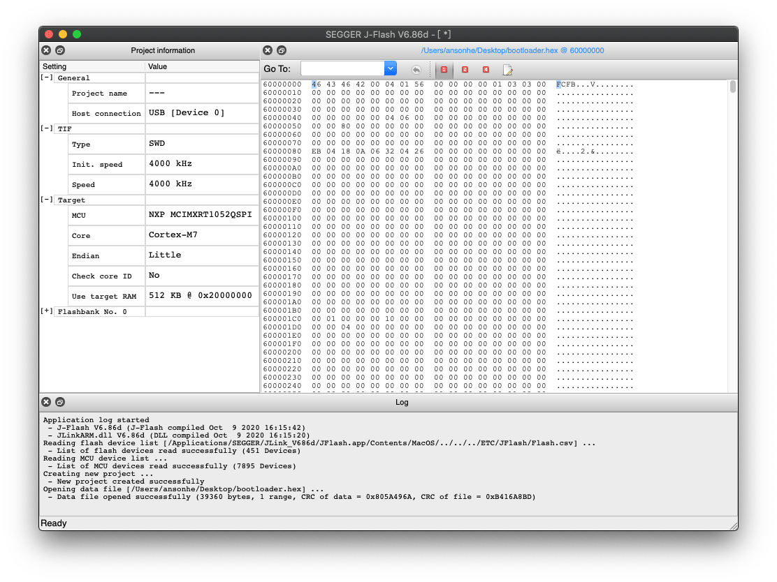
Drag this hex bootloader into the J-Flash.
Connect J-Link's SWD pins to Arch Mix's SWD Pins.
- DIO to DIO
- CLK to CLK
- GND to GND
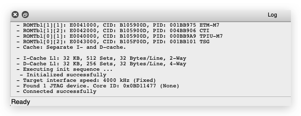
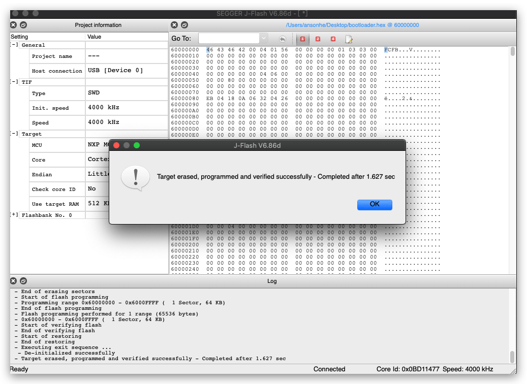
Select Target -> Connect from J-Flash top left drop down menu. Once connected, you should see:
If cannot connect, please check the wiring of J-Link and Arch Mix again.
- Select Target -> Production Programming to flash the bootloader to Arch Mix.
- Reset the Arch Mix and now the Arduino bootloader is flashed into it!
Arduino Get Started
- Add the Arch Mix board library to Arduino IDE:
Open your Arduino IDE, click on File > Preferences, and copy below url to Additional Boards Manager URLs:
https://files.seeedstudio.com/arduino/package_seeeduino_boards_index.json
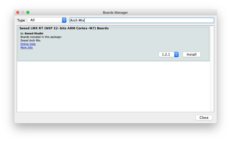
Click on Tools > Board > Board Manager and Search Arch Mix in the Boards Manager.
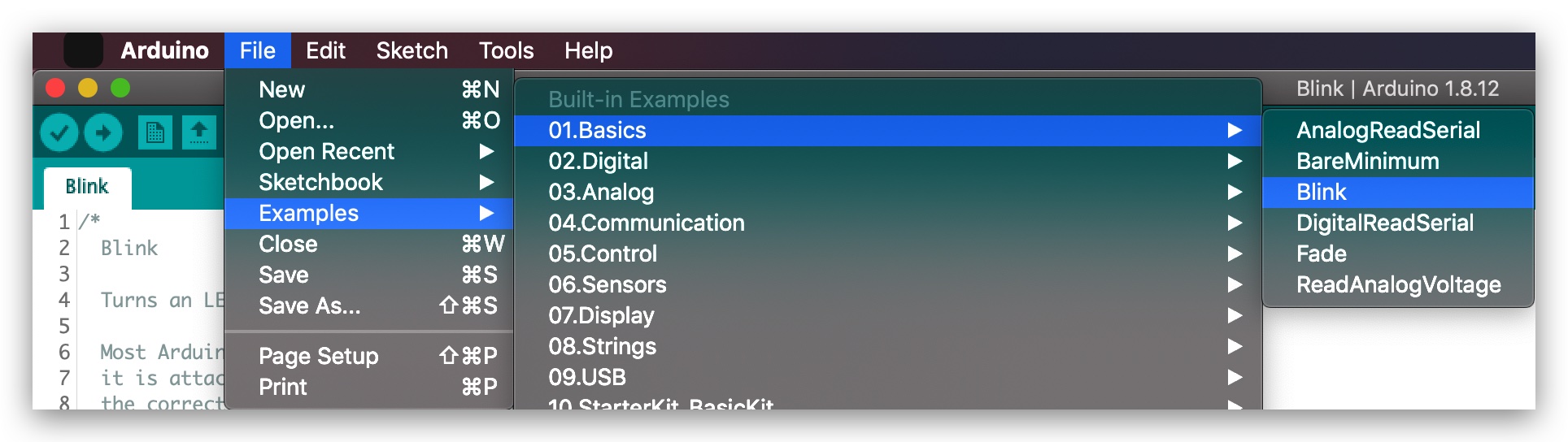
- Open the LED blink example sketch: File > Examples > 01.Basics > Blink.
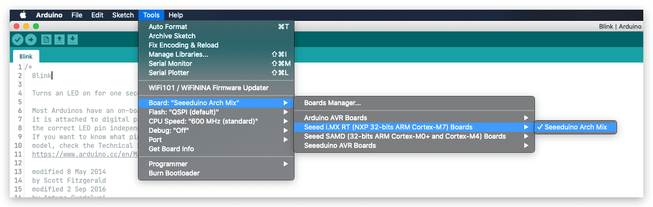
- You'll need to select the entry in the Tools > Board menu that corresponds to your Arduino. Selecting the Arch Mix.
- Choose the right port:
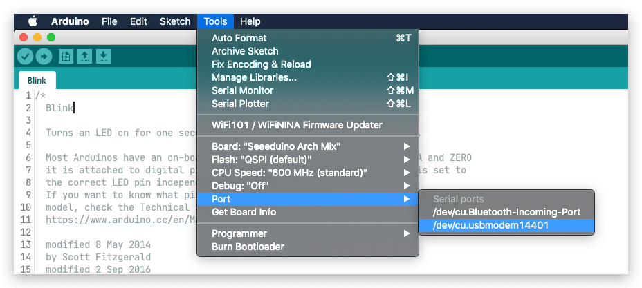
- Click upload and the LED on Arch Mix should starts to blink! Now you have a powerful Cortex M7 Board in hand!
For Arduino Pin Map, you can check here for more reference.
Using NXPBooTUtility to Flash Arduino Bootloader
If you do not have a J-Link in hand and there is also other way to flash the bootloader using NXP Boot Utility, but it only supports Windows.
- Download the NXP Boot Utility.
git clone https://github.com/JayHeng/NXP-MCUBootUtility
Navigate to the NXP-MCUBootUtility folder, go into
NXP-MCUBootUtility/binand open the the NXP-MCUBootUtility.exe.Connect Arch Mix's Rx Pin to 3.3V Pin using a Female Jumper wire and adjust the Switches to 0001
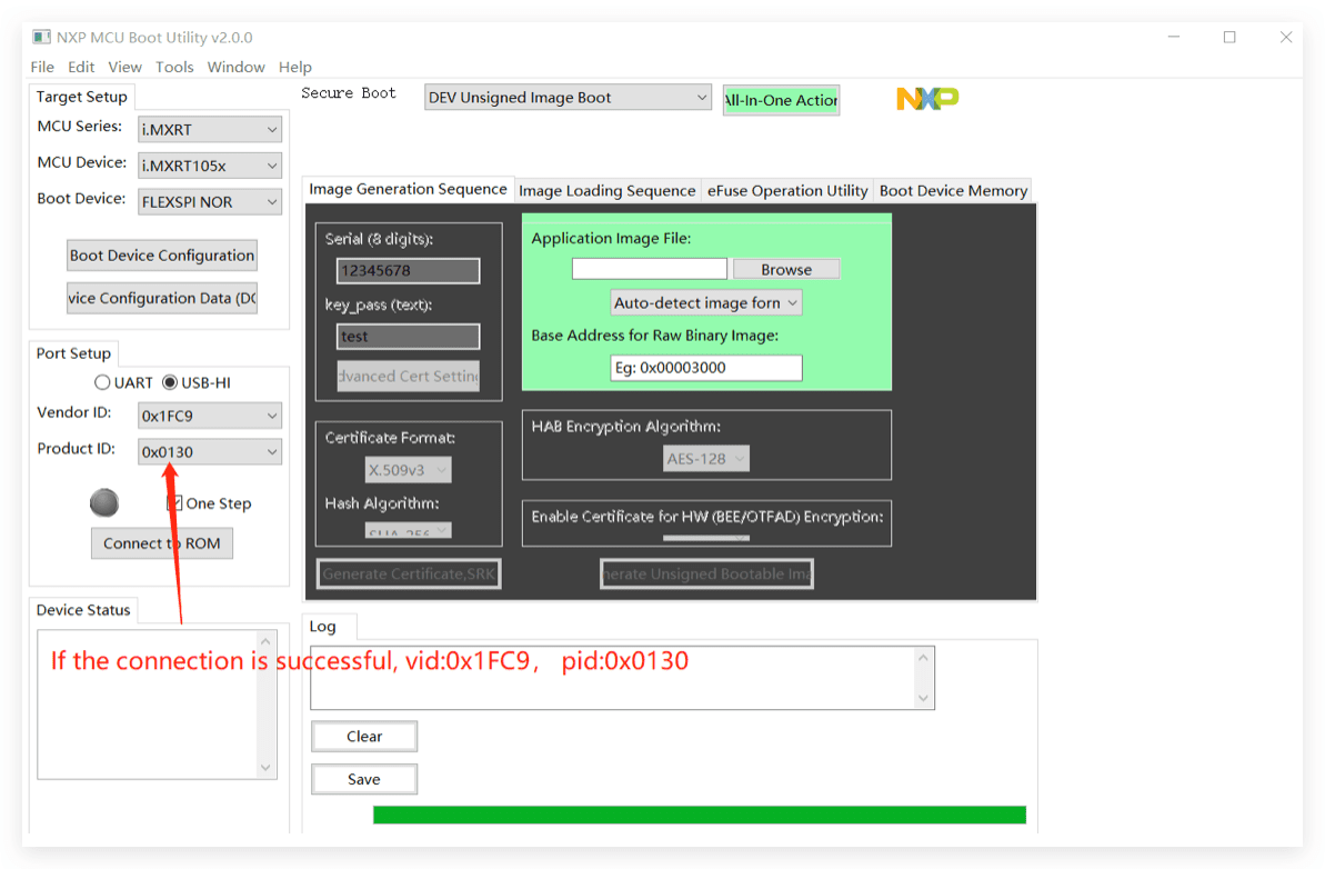
Connect the Arch Mix to your Computer and you should see the following screen:
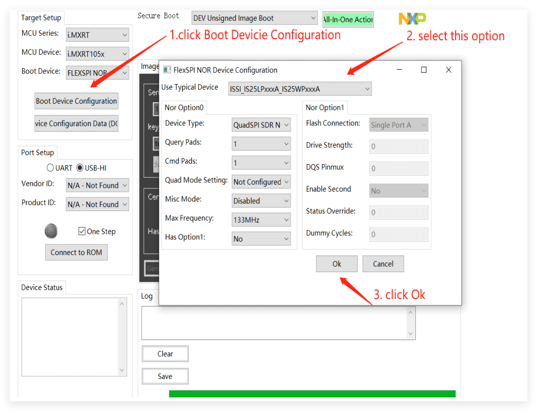
- Click the Boot Device Configuration, choose the Flash and click OK.
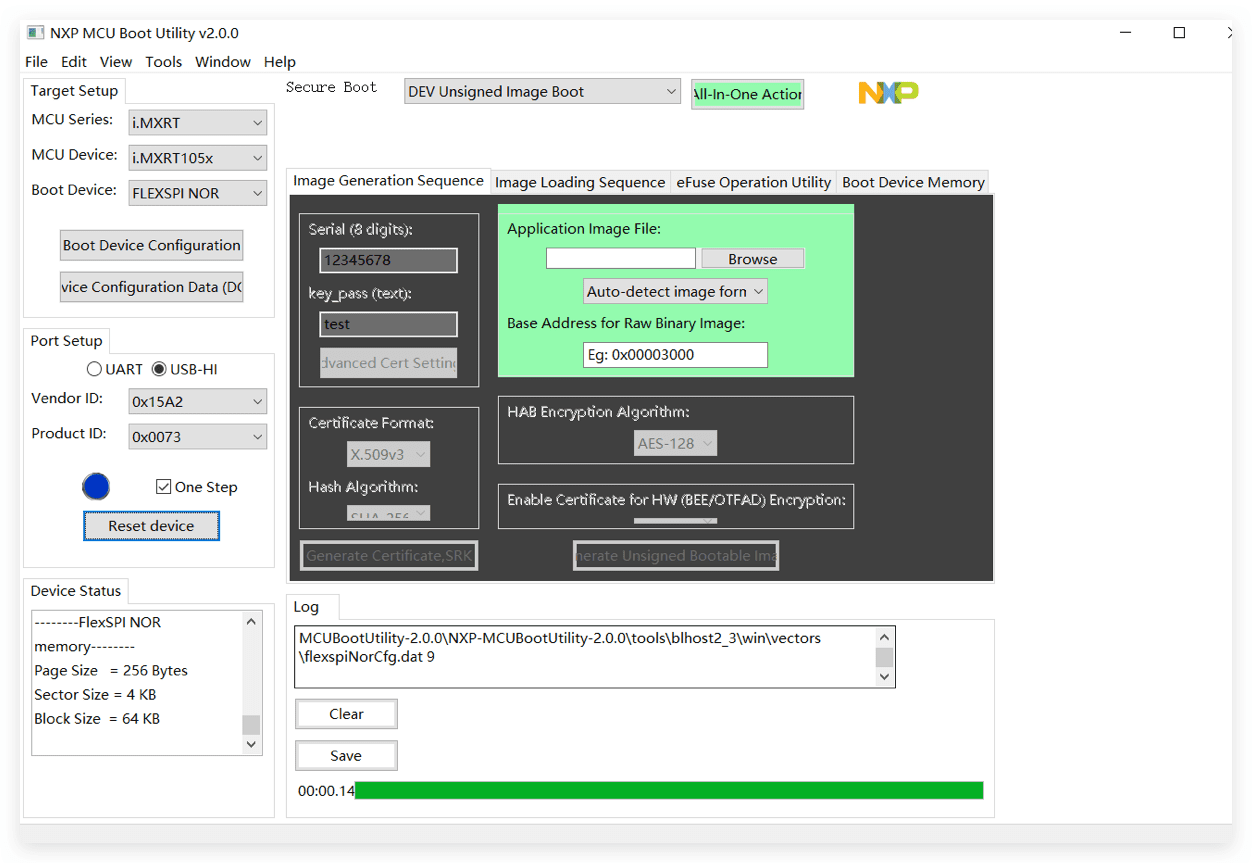
- Click Connect to ROM to enter the download mode:
- Choose the Bootloader:
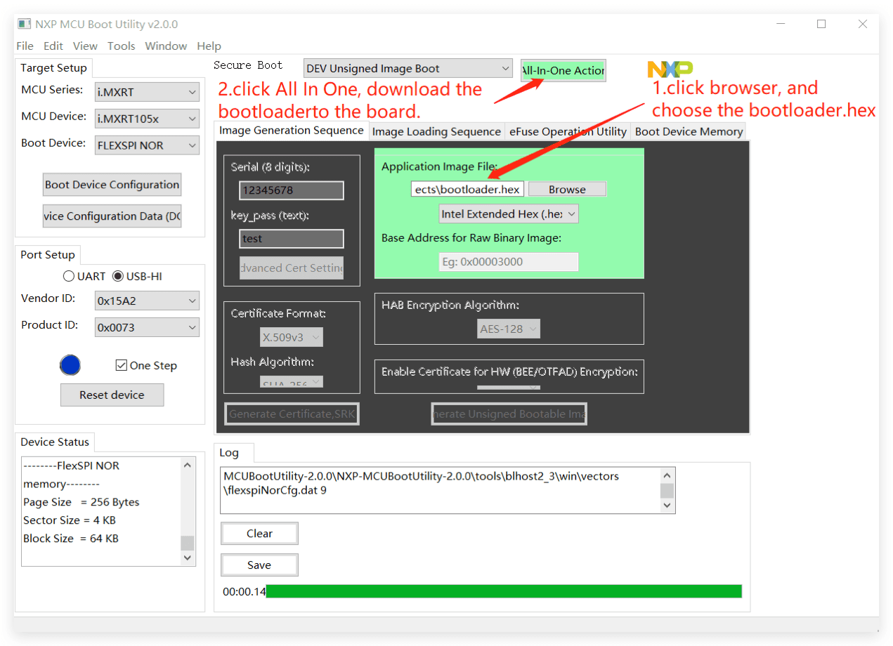
Click All in One Action and the it will download the bootloader to the Arch Mix!
Once flashed completed, adjust the switch back to 0010 and press reset. Now the Arduino Bootloader is flashed in the Arch Mix using the NXP Boot Utility!
Attention
Make sure the Switches are adjusted back to 0010 to enter boot from QSPI Flash and work as Arduino Dev Board.
Resources
Schematic Online Viewer
Resources
- [ZIP] Schematic
- [ZIP] Firmware and Tools
- [PDF] PDF Format Wiki
- [PDF] i.MX RT1050 Datasheet
- [PDF] Dimension Diagram
- [xlsx] Arch Mix_v1.0_Pin Function
Tech Support & Product Discussion
Thank you for choosing our products! We are here to provide you with different support to ensure that your experience with our products is as smooth as possible. We offer several communication channels to cater to different preferences and needs.