Guide for Codecraft using Arduino
Codecraft is a programming software based on Scratch3.0 and supports both graphical and text programming languages. It’s a versatile software tool for STEM education. With Codecraft, children are able to design engaging stories, games and animations, and use various electronic kits which CH Maker Ed and Seeedstudio provides to create interactive smart applications. Furthermore, when you’re ready, you can always convert the code blocks to Arduino, Python, or JavaScript to learn more about the most popular languages.
There are 2 modes in Codecraft which are Stage Mode and Device Mode. In Stage Mode, users can control an object which is called a “sprite” by using code blocks. Also, this mode can be used to help students learn about shapes, arithmetic and also other areas of math.
In Device mode, users can connect with a Grove Zero or an Arduino to build their cool projects by simply dragging and dropping code blocks into the IDE. LE
Codecraft
Blocks in device mode
Here are the main types of blocks used in Codecraft.
Stack Blocks

Stack Blocks are the blocks that perform the main commands. They are shaped with a notch at the top and a bump on the bottom — so blocks can be placed above and below them.
Boolean Blocks

Boolean blocks are the conditions - they are either true or false. For example, asking a computer: “Is 2+2=4?”, and it would either tell you “Yes” or “No”. Boolean blocks are hexagonal shape.
Reporter Blocks

Reporter blocks are the values. Reporter blocks can hold numbers and strings. It is like asking a friend, for example, “What is 2+2?”, and they would answer “4”. It is not just equations however, it can report a variable, for example, “What is your age?”. They may answer: “15”. It is shaped with round edges.
C Blocks

C blocks are blocks that take the shape of “C’s”. Also known as “Wrap blocks”, these blocks loop the blocks within Cs or check if a condition is true. There’re five C blocks, and they can be found in the Control category. C blocks can be bumped at the bottom, or capped.
Output Boolean Blocks

Output Boolean Blocks are hexagonal shaped blocks that checks if a condition is “true” or “false” and performs an operation once the condition is met. These block can be placed inside Boolean Blocks and C blocks.
Compatible Grove
Please refer to the CodeCraft Grove Compatible List to confirm if your Grove is supported.
Basic Tutorial
Step 1. Add Arduino Support
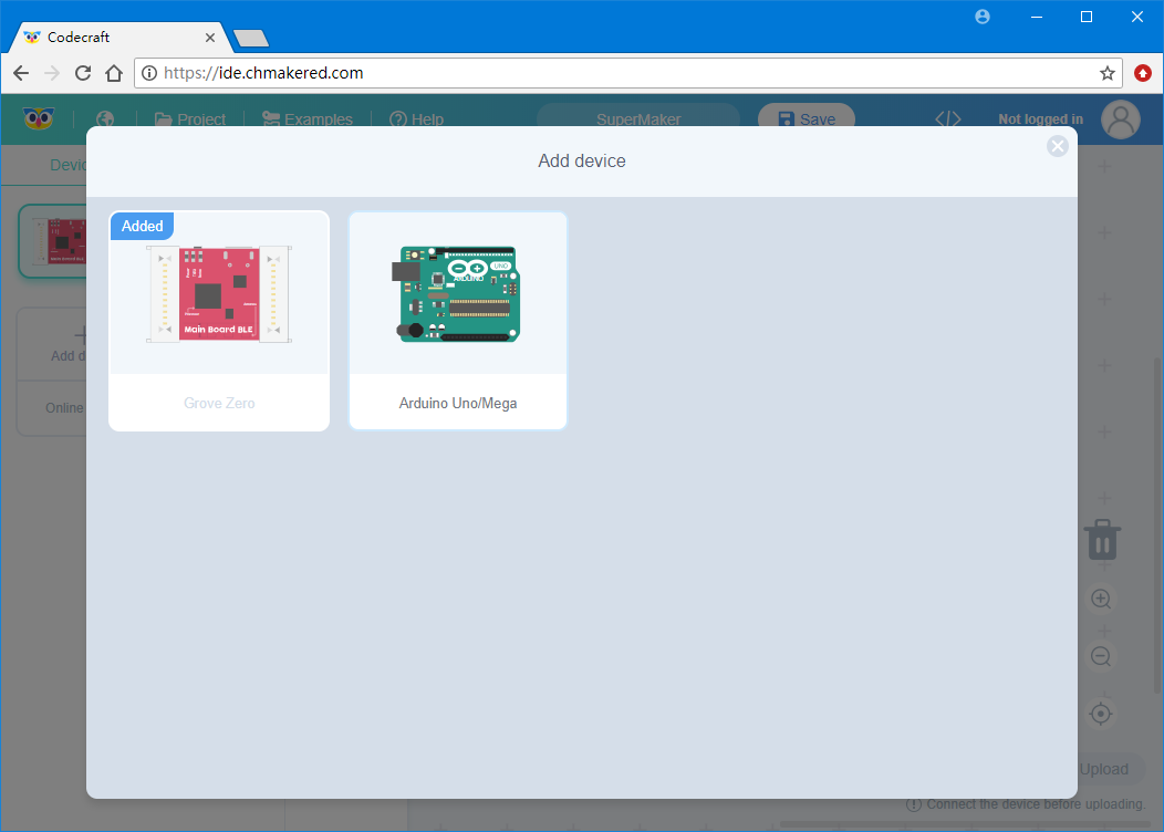
Codecraft can support both Grove Zero and Arduino Uno/Mega, so before using Codecraft with Arduino, you need to add Arduino support to it.
Please enter Codecraft, and click "Add device" in sidebar on the left, then choose "Arduino Uno/Mega".
Step 2. Install Codecraft Assistant
Codecraft Assistant can help you to upload code in Codecraft to Arduino, please refer CH MAKER Ed-Documents to download and install it.
Step 3. Arduino Main Procedure
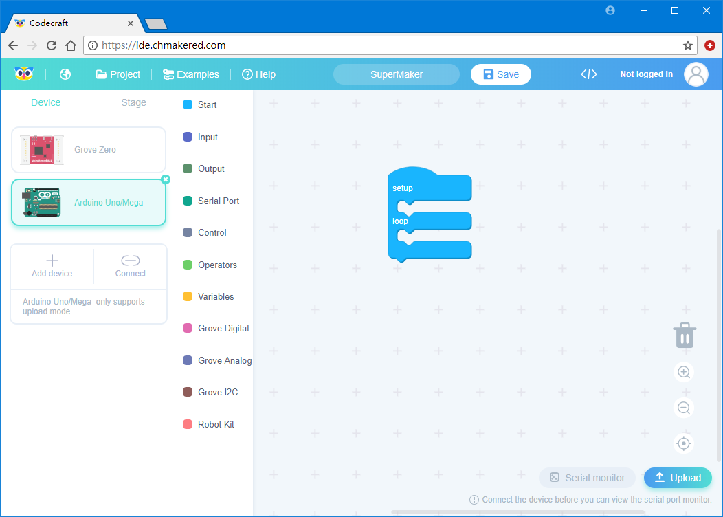
Generally, main procedure of Arduino includes two subprocedures, we call them setup and loop. The code in setup will run once when Arduino powered on, and run in loop repeatedly.
Main Procedure Block is included in Start tab on the left, you can use mouse to drag it to working area.
Step 4. Blinking an LED
We usually learn Arduino from blinking an LED, and there is an LED build-in Arduino boards, which is connected to Arduino's pin D13.
LED Block can be found in Grove Digital tab, drag it to loop procedure, and they will combine automatically.
Change LED Pin from D2 to D13 so that it can control the LED in D13 pin, then drag another LED Block below it, and make ON to OFF. The main procedure may looks like:

In order to see the LED blinking, we should add an interval between LED on and off. Delay Block can be found in Control tab, it is used to make a delay. Drag two Delay Blocks between two LED Blocks, and set interval to 1000ms (1000ms = 1s).

Now the program is completed.
Step 5. Upload to Arduino
We can upload the completed program to Arduino to make it effective, so please connect your Arduino to your PC. You can find the serial port number of Arduino in Device Manager, remember it for future use.
Now click upload in Codecraft's lower right corner, choose Arduino's serial port number. Confirm it and wait for a while, you will see an LED blinking in Arduino.

Grove Start Kit for Arduino
The following 10 lessons will help you become more familiar with how to use Codecrft. The Grove modules in these lessons all can be found in Grove - Start Kit for Arduino.
Lesson 1. Using Grove - LCD RGB Backlight

The Grove - LCD RGB Backlight supports text display, using user-defined characters. It enables you to set the backlight color, using the simple and concise Grove interface. It uses I2C as the communication method with your Arduino. So, the number of pins required for data exchange and backlight control shrinks from ~10 to 2, leaving more I/O capability for other challenging tasks.

"LCD RGB setColor" block can be used to set backlight color of LCD from R, G and B values. It can be found in Grove I2C tab.

"LCD RGB print" block can be used to print a string to LCD in specified location, it can be found in Grove I2C tab.
Objective
Change backlight color of LCD to a color you like, and print "hello, world!" and system running time on it.
Hardware
Step 1. Using a Grove cable connect Grove - LCD Backlight to Seeeduino's I2C port. If you are using Arduino, please take advantage of a Base Shield.
Step 2. Link Seeedino/Arduino to your PC via an USB cable.
Software
Step 1. Open Codecraft, add Arduino support, and drag a main procedure to working area.
Step 2. Drag a "LCD RGB setColor" block and a "LCD RGB print" block to setup subprocedure, let them be combined automatically.

Change R, G and B values in setColor block, then let print block print "hello, world!" in first column of first line.
Step 3. Drag another "LCD RGB print" block to loop subprocedure, change row and column of it to 2 and 1. Then drag a "System running time" block to it, which can be found in Input tab.
The "System running time" block returns the time from Seeeduino/Arduino being powered up to now in milliseconds, if you want to get that time in seconds, you can divide it by 1000. Division block can be found in Operators tab.

When the code finishes uploaded, you can see the backlight color of LCD turn to you set, and "hello, world!" & system running time shown on it.
Lesson 2. Using Grove - Relay

The Relay is a useful tool to magnify your Arduino’s control ability! Feed the control signal through the Grove interface and the relay open or close the external circuit that is connected to the screw terminals. The voltage of the external circuit can run up to 220V! So grab this relay and start some really tough projects!

Relay block can be used to control Relay to turn ON or turn OFF, it can be found in Grove Digital tab.
Objective
Using a Grove - Button to control a Grove - Relay, when button pushed, turn on the relay. Otherwise, turn off the relay.
Hardware

Step 1. Using two Grove cables connect a Grove - Button to port D3, connect a Grove - Relay to port D8 in a Base Shield.
Step 2. Plug the Base Shield to your Seeeduino/Arduino.
Step 3. Link Seeeduino/Arduino to your PC via an USB cable.
Software
Step 1. Open Codecraft, add Arduino support, and drag a main procedure to working area.
Step 2. Create a variable to store button's state. Turn to Variables tab, click "Make a Variable" button, and name the variable we will create, like buttonState.

Click OK, now buttonState block appeared in Variables tab.
Step 3. Drag "set buttonState to 0" block to loop subprocedure, and drag Button block to it.

Step 4. We need to turn on the relay when the button is pressed, otherwise turn off it. So we need an n"if...then...else" block in Control tab and a Equal block in Operator tab, drag them to loop subprocedure, and let them combine with buttonState variable.

Step 5. Finally drag Relay block to them, upload to Arduino, all done.

When the code finishes uploaded, if you push the button, relay will be turned on. Otherwise, relay will be turned off.
Lesson 3. Using Grove - Sound Sensor

The Sound sensor module is a simple microphone. Based on an LM358 amplifier and an electret microphone, it can be used to detect the sound level in the environment.

Sound block can be used to sense the size of the sound in the environment, it can be found in Grove Analog tab.
Objective
Monitor the sound level in the environment. If it is too loud, flashing an LED as an alarm.
Hardware

Step 1. Using two Grove cables connect a Grove - Sound Sensor to port A0, connect a Grove - Red LED to port D7 in a Base Shield.
Step 2. Plug the Base Shield to your Seeeduino/Arduino.
Step 3. Link Seeeduino/Arduino to your PC via an USB cable.
Software
Step 1. Open Codecraft, add Arduino support, and drag a main procedure to working area.
Step 2. Please refer to "Grove - Relay" section to create a variable to store the size of sound, then using "if...then" block in Control tab determine if the sound size exceeds the threshold.

Step 3. If the sound size exceeds the threshold, blink the led.

When the code finishes uploaded, if the sound in the environment if too loud, the LED will be flashing.
Lesson 4. Using Grove - Touch Sensor

The Grove - Touch Sensor enables you to replace pressure on a button with contact on a detecting surface. It can detect the change in capacitance when a finger is nearby. So, whether your finger touches the pad directly or just stays close to it, the Grove - Touch Sensor would output HIGH.

Touch block can be used to read status of the touch, it can be found in Grove Digital tab.
Objective
Using a Grove - Touch Sensor to control Grove - Red LED. When sensor touched, turn on the LED, otherwise turn off the LED.
Hardware
Step 1. Using two Grove cables connect Grove - Touch Sensor to port D3, connect Grove - Red LED to port D7 in Base Shield.
Step 2. Plug the Base Shield to your Seeeduino/Arduino.
Step 3. Link Seeeduino/Arduino to your PC via an USB cable.
Software
Step 1. Open Codecraft, add Arduino support, and drag a main procedure to working area.
Step 2. The program more likes the program in "Grove - Relay" section, and we can build it without variables.

When the code finishes uploaded, if the sensor is touched, the LED will be turned on. Otherwise the LED will be turned off.
Lesson 5. Using Grove - Rotary Angle Sensor

The Grove potentiometer produces analog output between 0 and VCC (3.3 or 5 VDC). The angular range is 300 degrees, with a linear change in value. The resistance value is 10k ohms, perfect for Arduino use. This may also be known as a “rotary angle sensor”.

Rotation block can be used to read status of the rotation, it can be found in Grove Analog tab.
Objective
Display the rotation of Grove - Rotary Angle Sensor in Serial.
Hardware

Step 1. Using a Grove cable connect Grove - Rotary Angle Sensor to port A0 in Base Shield.
Step 2. Plug the Base Shield to your Seeeduino/Arduino.
Step 3. Link Seeeduino/Arduino to your PC via an USB cable.
Software
Step 1. Open Codecraft, add Arduino support, and drag a main procedure to working area.
Step 2. Before using Serial port, we should set its baud rate, drag "Serial baud rate" block from Serial Port tab to setup subprocedure, and select 9600 bps.

Step 3. "Serial println" block can be used to display a new line in serial port, we can combine it with Rotation block.

Step 4. After the program is uploaded, clicking Connect button in the left of Codecraft, and choose your Arduino's port, then Connect.


Rotate Rotary Angle Sensor, you can see data changes in monitor.
Lesson 6. Using Grove - LED

Grove - LED is designed for the beginners of Arduino/Seeeduino to monitor controls from digital ports. It can be mounted to the surface of your box or desk easily and used as pilot lamp for power or signal.


LED block can be used for acting as Digital OUTPUT or Analog OUTPUT, when acting as Analog OUTPUT, you can control its brightness.
Objective
Make a breathing LED.
Hardware

Step 1. Using a Grove cable connect Grove - Red LED to port D3 in a Base Shield.
Step 2. Plug the Base Shield to your Seeeduino/Arduiono.
Step 3. Link Seeeduino/Arduino to your PC via an USB cable.
Software
Step 1. Open Codecraft, add Arduino support, and drag a main procedure to working area.
Step 2. It's very simple to make an LED breathing by using LED block in Grove Analog tab.
Other than that, we also need "count with...from...to...step" block in Control tab to calculate the brightness of LED. Drag it combine with loop subprocedure.

Step 3. Make sure let variable i from 0(darkness) to 255(brightest), then add "LED" block and "Delay ms" block to it, and LED's brightness to variable to i.

Step 4. The program above make LED from darkest to brightest, now we can add program let it from brightest to darkest.

When the code finishes uploaded, you will see the LED breathing.
Lesson 8. Using Grove - Light Sensor

The light sensor, also known as the light dependent resistor (LDR). Typically, the resistance of the light sensor will decrease when the ambient light intensity increases.

Light block can be used to detect light intensity in the environment via Analog INPUT, it can be found in "Grove Analog" tab.
Objective
Build a program like smart house, when the light intensity falls below the preset threshold, turn on the LED.
Hardware

Step 1. Using two Grove cables connect a Grove - Red LED to port D7, connect a Grove - Light Sensor to port A0 in a Base Shield.
Step 2. Plug the Base Shield to your Seeeduino/Arduino.
Step 3. Link Seeeduino/Arduino to your PC via an USB cable.
Software
Step 1. Open Codecraft, add Arduino support, and drag a main procedure to working area.
Step 2. We have used "if" block in Grove - Touch Sensor section, so it's not hard to build this program.

When the code finishes uploaded, blocking the light to the Light Sensor, the LED will be turned on.
Lesson 9. Using Grove - Button

This new version of button Grove module contains one independent button, which are configured with pull-down resistor – ready for use with our microcontrollers as digital input. The button signals the SIG wire,NC is not used on this Grove module.

Button block can be used to detecte the status of a momentary pushbutton via Digital INPUT, it can be found in Grove Digital tab.
Objective
Using a Grove - Button to control a Grove - Red LED. When button is pushed, turn on the LED, otherwise turn off the LED.
Hardware

Step 1. Using two Grove cables connect Grove - Button to port D3, connect Grove - Red LED to port D7 in a Base Shield.
Step 2. Plug the Base Shield to your Seeeduino/Arduino.
Step 3. Link Seeeduino/Arduino to your PC via an USB cable.
Software
Step 1. Open Codecraft, add Arduino support, and drag a main procedure to working area.
Step 2. We have used Button in Grove - Relay section, now let's change the Relay to a LED, and use Button to control it.

When the code finishes uploaded, if button is pushed, turn on the LED. Otherwise turn off the LED.
Lesson 10. Using Grove - Servo

This is an actuator whose position can be precisely controlled.

Servo block can be used to control the servo by assigning the amount of rotation and the delay between each rotation, it can be found in Grove Analog tab.
Objective
Using a Grove - Rotary Angle Sensor to control a Grove - Servo.
Hardware

Step 1. Connect Grove - Servo to a Base Shield, and using a Grove cable connect Grove - Rotary Angle Sensor to port A0 in the Base Shield.
Step 2. Plug the Base Shield to your Seeeduino/Arduino.
Step 3. Link Seeeduino/Arduino to your PC via an USB cable.
Software
Step 1. Open Codecraft, add Arduino support, and drag a main procedure to working area.
Step 2. We can use Rotary Angle Sensor to control Servo, but since the value of "Rotation" block is 0 to 1023, so we need to divide by a number, let it in 0 to 180.

When the code finishes uploaded, rotate Rotary Angle Sensor, the angle of the Servo motor will change.
Thank you for choosing our products! We are here to provide you with different support to ensure that your experience with our products is as smooth as possible. We offer several communication channels to cater to different preferences and needs.