Gear Stepper Motor Driver Pack

The Gear Stepper Motor Driver Pack includes a stepper motor and a motor drive board. It's a four-phase eight-stepping stepper motor, and you can easily control this stepper motor via the drive board.
You can use this pack for position control.

Features
- Low noise
- Large torque
- Built-in gearbox
Specification
| Item | Value |
|---|---|
| Operating Voltage | 5V |
| Phase | 4 |
| Reduction ratio | 1/64 |
| Step Angle | 5.625°/64 |
| Diameter | 28mm / Nema 11 |
| Idle In-traction Frequency | >500HZ |
| Idle Out-traction Frequency | >1000HZ |
| Resistance | 21±7% |
| Noise | ≤40dB |
| Drive mode | four-phase eight-stepping |
Typical applications
- Desktop printers
- Plotters
- 3d printers
- CNC milling machines
Hardware Overview
Pin Out


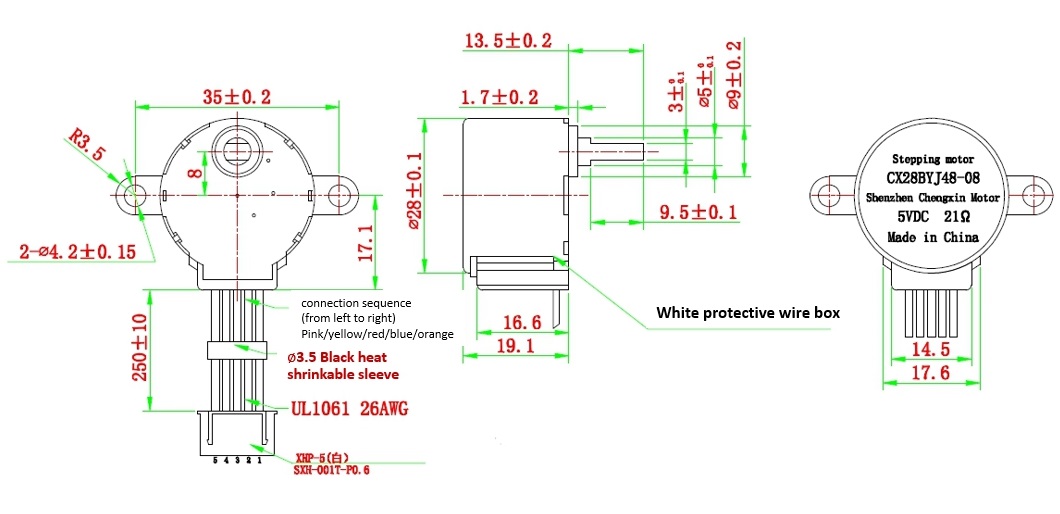
Mechanical drawing
you can click it to see the original picture.
Platforms Supported
| Arduino | Raspberry Pi | |||
|---|---|---|---|---|
The platforms mentioned above as supported is/are an indication of the module's software or theoritical compatibility. We only provide software library or code examples for Arduino platform in most cases. It is not possible to provide software library / demo code for all possible MCU platforms. Hence, users have to write their own software library.
Getting Started
Play With Arduino
Hardware
Materials required
| Seeeduino V4.2 | Gear Stepper Motor Driver Pack | Female-Male jumpers |
|---|---|---|
 |  |  |
| Get One Now | Get One Now | Get One Now |
1 Please plug the USB cable gently, otherwise you may damage the port. Please use the USB cable with 4 wires inside, the 2 wires cable can't transfer data. If you are not sure about the wire you have, you can click here to buy
2 To make the Gear-Stepper-Motor-Driver-Pack work with your Arduino, several Female-Male jumpers is also required. In case you do not have jumpers, you can click here to buy.
- Step 1. Connect the Gear Stepper Motor Driver Board to your seeedunio via jumppers.
| Seeeduino | Gear Stepper Motor Driver Board |
|---|---|
| Digital Pin 8 | IN1 |
| Digital Pin 9 | IN2 |
| Digital Pin 10 | IN3 |
| Digital Pin 11 | IN4 |
| GND | GND |
| VCC_5V | VCC |
| VCC_5V | VM |
You can connect the VM pin to VCC_5V or you can just do not use it as long as you choose the VCC in the switch.
-
Step 2. Plug the stepper motor into the Gear Stepper Motor Driver Board.
-
Step 3. Connect Seeeduino to PC via a USB cable.

Software
If this is the first time you work with Arduino, we strongly recommend you to see Getting Started with Arduino before the start.
- Step 1. Click the icon
 in upper right corner of the code block to copy the following code into a new sketch in the Arduino IDE.
int pwm1=9;
int pwm2=10;
int ctr_a =9;
int ctr_b =8;
int ctr_c =11;
int ctr_d =10;
int sd =6;
int i=0;
int t=1500;

void setup()
{
    pinMode(ctr_a,OUTPUT);
    pinMode(ctr_b,OUTPUT);
    pinMode(ctr_c,OUTPUT);
    pinMode(ctr_d,OUTPUT);
    delay(1);
}


void loop ()
{
   for(i=1500;i>=1;i--)
   {
       digitalWrite(ctr_a,LOW);//A
       digitalWrite(ctr_b,HIGH);
       digitalWrite(ctr_c,HIGH);
       digitalWrite(ctr_d,HIGH);
       delayMicroseconds(t);
       digitalWrite(ctr_a,LOW);
       digitalWrite(ctr_b,LOW);//AB
       digitalWrite(ctr_c,HIGH);
       digitalWrite(ctr_d,HIGH);
       delayMicroseconds(t);
       digitalWrite(ctr_a,HIGH);
       digitalWrite(ctr_b,LOW);//B
       digitalWrite(ctr_c,HIGH);
       digitalWrite(ctr_d,HIGH);
       delayMicroseconds(t);
       digitalWrite(ctr_a,HIGH);
       digitalWrite(ctr_b,LOW);
       digitalWrite(ctr_c,LOW);//BC
        digitalWrite(ctr_d,HIGH);
       delayMicroseconds(t);
       digitalWrite(ctr_a,HIGH);
       digitalWrite(ctr_b,HIGH);
       digitalWrite(ctr_c,LOW);//C
       digitalWrite(ctr_d,HIGH);
       delayMicroseconds(t);
       digitalWrite(ctr_a,HIGH);
       digitalWrite(ctr_b,HIGH);
       digitalWrite(ctr_c,LOW);//CD
       digitalWrite(ctr_d,LOW);
       delayMicroseconds(t);
        digitalWrite(ctr_a,HIGH);
       digitalWrite(ctr_b,HIGH);
       digitalWrite(ctr_c,HIGH);//D
       digitalWrite(ctr_d,LOW);
       delayMicroseconds(t);
       digitalWrite(ctr_a,LOW);
       digitalWrite(ctr_b,HIGH);
       digitalWrite(ctr_c,HIGH);//DA
       digitalWrite(ctr_d,LOW);
       delayMicroseconds(t);

   }
}
- Step 2. Upload the demo. If you do not know how to upload the code, please check How to upload code.
If every thing goes well, you can see the motor run:

Raspberry Pi + Python
Materials required
| Pi Pico | Gear Stepper Motor Driver Pack | Female-Female jumpers |
|---|---|---|
 | | |
| Get One Now | Get One Now | Get One Now |
Background
The stepper motor has 4 separate electromagnets inside which you must power one by one in sequence in order to turn one notch on the gear. The gear has 64 notches, so you need to do this 64 times for one complete revolution of the axle.
You can do this yourself by powering the pins one by one, or using a library such as RpiMotorLib.
Method
-
If you didn't already, follow this guide to get set up with your Raspberry Pi Pico running Python through Thonny + picozero on your computer.
-
Connect the Gear Stepper Motor Driver Board to your Pi Pico using jumpers.
Pi Pico Gear Stepper Motor Driver Board VBUS VCC GND GND GP2 IN1 GP3 IN2 GP4 IN3 GP5 IN4 -
Look closely at your Gear Stepper Motor Driver Board and you'll see a teeny tiny switch which says VCC at one end and VM on the other. This lets you choose whether to power the motor from the same pin as the driver (VCC), or a separate voltage source (VM). For now we'll just use VCC. Make sure the switch is on VCC.
-
Plug your Pi Pico into your computer over USB (or connect to it wirelessly) and load up Thonny.
-
Upload the following code to Thonny and run it.
from gpiozero import Button, LED
from time import sleep

wait = 0.001 # seconds

ctrA = LED(2) # IN1
ctrB = LED(3) # IN2
ctrC = LED(4) # IN3
ctrD = LED(5) # IN4

while True:
  # A
  ctrA.on()
  ctrB.off()
  ctrC.off()
  ctrD.off()
  sleep(wait)

  # AB
  ctrA.on()
  ctrB.on()
  ctrC.off()
  ctrD.off()
  sleep(wait)

  # B
  ctrA.off()
  ctrB.on()
  ctrC.off()
  ctrD.off()
  sleep(wait)

  # BC
  ctrA.off()
  ctrB.on()
  ctrC.on()
  ctrD.off()
  sleep(wait)

  # C
  ctrA.off()
  ctrB.off()
  ctrC.on()
  ctrD.off()
  sleep(wait)

  # CD
  ctrA.off()
  ctrB.off()
  ctrC.on()
  ctrD.on()
  sleep(wait)

  # D
  ctrA.off()
  ctrB.off()
  ctrC.off()
  ctrD.on()
  sleep(wait)

  # DA
  ctrA.on()
  ctrB.off()
  ctrC.off()
  ctrD.on()
  sleep(wait)
What's going on here? The stepper motor has 4 separate electromagnets inside. You are powering them one by one in a loop, which turns the gear by one notch. Do this 64 times very fast and the axle turns one full rotation!
Using a library
You can also use libraries like RpiMotorLib to cut out the hard part:
-
Thonny -> Tools -> Manage packages -> search for
RpiMotorLib-> install -
Follow the same wiring steps from the previous section
-
Replace your code with this:
from RpiMotorLib import RpiMotorLib

GpioPins = [2, 3, 4, 5]
mymotortest = RpiMotorLib.BYJMotor("MyMotorName", "28BYJ")
mymotortest.motor_run(GpioPins, 0.001, 512, False, False, "half", 0.05)
The "28BYJ" bit above refers to the model of stepper motor you're using. You can find explanations for the other arguments in the RpiMotorLib documentation. (this uses a different driver board but most stuff is the same).
Resources
Tech Support & Product Discussion
Thank you for choosing our products! We are here to provide you with different support to ensure that your experience with our products is as smooth as possible. We offer several communication channels to cater to different preferences and needs.