Grove - XBee Carrier
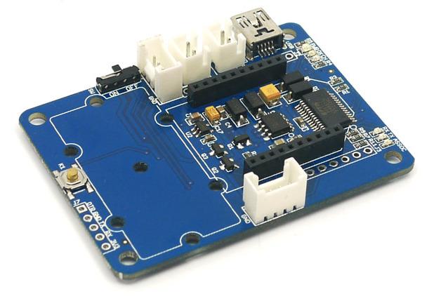
The Grove - XBee Carrier is a Wireless Sensor Network (WSN) base board designed for Bee series and Grove units. It is primarily suitable for standalone Bee Nodes like RFBee, Wifi Bee which have ATMega328 onboard and XBee (Zigbee) modules. It is compatible with RFBee, Wifi Bee, XBee and Bluetooth Bee. Besides a Bee receptacle, there are also two Grove connectors. The board can be powered by a lithium battery or through USB cable. You can use a Wireless charger, Solar Panel or the USB cable to charge the battery. The FT232RL chip onboard helps in downloading the program to Bee Module directly.
Bees which do not have ATMega328 like Bluetooth Bee can only be configured by using on-board FT232RL (USB to UART). Theses Bees are not suitable for standalone applications.
The on-board FT232RL can be used like any other 3.3V USB to UART interface when not connected to any Bee Modules. This is useful for programming a 3.3V MCU through Serial Port.

Features
-
Bees Compatible Receptacle
-
Two Grove Connectors
-
Two Grove Place Holders
-
LEDs for PWR, Charge Indication and UART transmission.
-
Power Switch
-
Reset Button
Application Ideas
-
Wireless Sensor Network with Standalone Bee Node like Wifi Bee.
-
As a configuration aid for Bees using FT232RL.
-
Charger for Lithium Ion Cells using on-board charge controller.
-
As a FT232RL based 3.3v USB-UART.
Cautions
- Insert the Bees in the proper direction. Use the Bee outline on the silk-screen.
Specification
| Item | Min | Typical | Max | Unit |
|---|---|---|---|---|
| Voltage | 3.0 | 3.3 | 3.6 | VDC |
| Charge Controller | CN3063 | |||
| CHARGER (Charging Voltage for LiPo Battery) | 4.4V to 6V (as per CN3063 Spec) | |||
| Charging Current | Max 500mA | |||
| 3.3V LDO | Low Noise and Micropower type. Suitable for Battery Application. | |||
| I/O Logic | 3.3V Logic | |||
Interface Function

U2: RT9167A_33PB IC, 3.3V LDO Lownoise Micropower Regulator U3: CN3083 IC, Charger controller for Lithium batteries (charging using solar panel) U4: FT232RL IC, USB to serial UART interface
Usage
When using an RFBee, the following pinouts of ATmage168 on RFBee apply for using the Arduino IDE
Pin 5 is the Grove connector for I/O - Yellow wire Pin 6 is the Grove connector for I/O - White wire
Pin 16 may need to be driven low to provide enough power to the I/O Grove [via mosfet] Pin 17 may need to be driven low to provide enough power to the I2C Grove [via mosfet]
Note: you can use the x2 Grove cable with the white and yellow wires swapped on one to access both I/O.
Hardware Installation
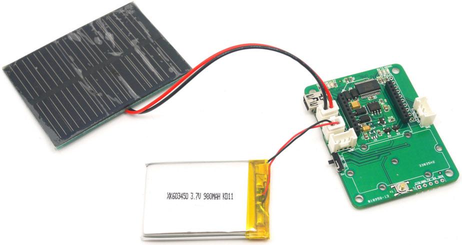
Charging
-
Connect a 3.7v LiPo battery to BAT JST-socket.
-
Connect a power source like Solar Panel to CHARGER JST-Socket.
-
The Battery will be continuous charged. The end of charging would be indicated by LED marked 'OK'.
Working with Standalone Bee Nodes
Bee Nodes are standalone Arduino Compatible Wireless Nodes. SeeedStudio has two such Nodes - Wifi Bee and RFBee.
-
The following image illustrated the connection of WiFi Bee to Grove - XBee Carrier.
-
Any Groves can be connected to the Grove sockets provided.
-
The programming of WiFi Bee's onboard AtMega328P is carried by connecting to PC through USB port. (FT232RL is used)

Bee Stem Connected to Wifi BEE and A Twig.jpg

Bee Stem Connected To RFBee And TwoTwigs.jpg
Working with Bee Modules
This section is about those Bee modules which do not have a MCU pre-programmed with Arduino bootloader. They mostly act just like a wireless trans-receiver. These Bee Modules like Bluetooth Bee, etc.. can communicated with PC as well. In this case, Grove - XBee Carrier acts as a carrier for these Bees providing necessary power, communication interface with PC through FT232RL USB to UART.

-
The communication of Bluetooth Bee and PC is captured with a serial port terminal application.
-
You can see the commands and their reply in the screenshot below.
-
The Bluetooth Bee was put into INQ mode and it even has detected a Bluetooth device in the vicinity.

Programming
/*
  Test code for use with an XBee Carrier & an RF Bee

  Turns on PD5 (eg: grove relay) on for one second, then off for one second, repeatedly.
*/

void setup()
{
    // initialize the digital pin as an output [Pin 5 is the Grove connector for I/O
    pinMode(5, OUTPUT);

    // These lines are needed to ensure that the relay will pull in [provides power to the Grove]
    pinMode(16, OUTPUT);
    digitalWrite(16, LOW);
}

void loop() {
    digitalWrite(5, HIGH);   // set the LED on
    delay(1000);              // wait for a second
    digitalWrite(5, LOW);    // set the LED off
    delay(1000);              // wait for a second
}
Version Tracker
| Revision | Descriptions | Release |
|---|---|---|
| v0.9b | Initial public release | 13th July 2011 |
Schematic Online Viewer
Resources
Tech Support & Product Discussion
Thank you for choosing our products! We are here to provide you with different support to ensure that your experience with our products is as smooth as possible. We offer several communication channels to cater to different preferences and needs.