Grove - 2-Channel Inductive Sensor(LDC1612)

The Grove - 2-Channel Inductive Sensor is based on Texas Instruments(TI) LDC1612, a 28-bit inductance to digital converter(LDC) for inductive sensing solutions. With multiple channels and support for remote sensing, the LDC1612 enables the performance and reliability benefits of inductive sensing to be realized at minimal cost and power. Inductance is an effect caused by the magnetic field of a current-carrying conductor acting back on the conductor. So by sensing the inductance, this sensor can detect the proximity of conductors especially metal nearby.
Feature
- 2 Channels With Matched Sensor Drive
- Easy-to-Use: Minimal Configuration Required
- Multiple Channels Support Environmental and Aging Compensation
- Remote Sensor Position of >20 cm Supports Operation In Harsh Environments
- Coil Parameter: Diameter: 16mm/ Turns: 20
Specification
| Item | Value |
|---|---|
| Supply Voltage | 3.3V / 5V |
| Junction Temperature | -55~150℃ |
| Supported Sensor Frequency Range | 1kHz~10MHz |
| Best Detecting Range | 15mm |
| Interface | I2C |
| I2C address | 0x2B(defult) 0x2A(configurable) |
| Package size | L: 140mm W: 90mm H: 10mm |
| Gross Weight | 12g |
When the ADDR pin is set low, the LDC I2C address is 0x2A; when the ADDR pin is set high, the LDC I2C address is 0x2B.
Typical applications
- Knobs in consumer, appliances, and automotive
- Linear and rotational encoders
- Buttons in home electronics, wearables, manufacturing, and automotive
- Keypads in manufacturing and appliances
- Slider buttons in consumer products
- Metal detection in industrial and automotive
- POS and EPOS
- Flow meters in consumer and appliances
Hardware Overview
Pin Out


1. Set the Rb(resistance unit-kom), L(inductance unit-uH), C(capacitance unit-pf) by the APIs if you don't use the Coil Inductance we provided. Used to calculate and set the corresponding frequency register of the sensor.
2. There is an INT-pad on the sensor board, It turns to the low level when the conversion is complete, overwise stays high, but you should configure the corresponding register of the sensor.
Working Principle
LDC1612 works based on measuring the parameters of the LC oscillator, formed by the PCB copper trace and the capacitor.
LDC1612 is able to measure the amount of energy it needs to provide to maintain the LC oscillation when a conductive object which is magnetically coupled with the LC oscillator approach. As the power loss of the oscillator circuit is proportional to the impedance of the conducting object, and the impedance value is affected by the distance of the object, it can then be used to determine the distance between the object and the LC oscillator. In this case, the PCB copper trace can be seen as an impedance sensor.
Platforms Supported
| Arduino | Raspberry Pi | |||
|---|---|---|---|---|
 |  |  |  |  |
The platforms mentioned above as supported is/are an indication of the module's software or theoritical compatibility. We only provide software library or code examples for Arduino platform in most cases. It is not possible to provide software library / demo code for all possible MCU platforms. Hence, users have to write their own software library.
Getting Started
Play With Arduino
Hardware
Materials required
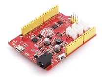
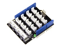
| Seeeduino V4.2 | Base Shield | Grove - 2-Channel Inductive Sensor |
|---|---|---|
 |  |  |
| Get ONE Now | Get ONE Now | Get ONE Now |
1 Please plug the USB cable gently, otherwise you may damage the port. Please use the USB cable with 4 wires inside, the 2 wires cable can't transfer data. If you are not sure about the wire you have, you can click here to buy.
2 Each Grove module comes with a Grove cable when you buy. In case you lose the Grove cable, you can click here to buy.
Step 1. Connect the Grove - 2-Channel Inductive Sensor(LDC1612) to port I^2^C of Grove-Base Shield.
Step 2. Plug Grove - Base Shield into Seeeduino.
Step 3. Connect Seeeduino to PC via a USB cable.

Now, we will demonstrate you how to run the code for coin distance detection, similar procedure if you wish to run other programs.
Software
If this is the first time you work with Arduino, we strongly recommend you to see Getting Started with Arduino before the start.
Step 1. Download the Grove-2-Channel_Inductive_Sensor-LDC1612 Library from Github.
Step 2. Refer to How to install library to install library for Arduino.
Step 3. Restart the Arduino IDE. Open the example, you can open it in the following three ways:
Open it directly in the Arduino IDE via the path: File --> Examples -->Seeed Inductive Sensor LDC1612--> coin_test_demo.

Open it in your computer by click the basic_demo.ino which you can find in the folder XXXX\Arduino\libraries\examples\coin_test_demo\coin_test_demo.ino, XXXX is the location you installed the Arduino IDE.

Or, you can just click the icon
 in upper right corner of the code block to copy the following code into a new sketch in the Arduino IDE.
Coin demo This program allows user to detect the distance from the coin to the copper trace.
#include "Seeed_LDC1612.h"

LDC1612 sensor;
const u32 DISTANCE_00=44000000;  //do not detect
const u32 DISTANCE_00_01=60000000;  // distance:<1mm
const u32 DISTANCE_01_05=45000000;  // distance:1mm~5mm
const u32 DISTANCE_05_10=44250000; // distance:5mm~10mm
const u32 DISTANCE_10_15=44080000; // distance:10mm~15mm
const u32 DISTANCE_15_20=44020000; // distance:15mm~20mm

void setup()
{
    Serial.begin(115200);
    delay(100);
    Serial.println("start!");

    sensor.init();

    if(sensor.single_channel_config(CHANNEL_0))
    {
        Serial.println("can't detect sensor!");
        while(1);
    }


}


void loop()
{
    u32 result_channel1=0;
    u32 result_channel2=0;

    /*shows the status of sensor.*/
    //sensor.get_sensor_status();

    /*Get channel 0 result and parse it.*/
    sensor.get_channel_result(CHANNEL_0,&result_channel1);

    /*Test the distance between the coin and the sensor.
    Note that the accuracy is for reference only.
    Please suspend the sensor during the test! */
    if(0!=result_channel1)
    {
        if(result_channel1<DISTANCE_00)
        {
            Serial.println("There is no coin here!");
        }

        if(result_channel1>=DISTANCE_00_01)
        {
            Serial.println("The distance between the COIN is 0~1mm");
        }

        if(result_channel1<DISTANCE_00_01&&result_channel1>=DISTANCE_01_05)
        {
            Serial.println("The distance between the COIN is 1~5mm");
        }

        if(result_channel1<DISTANCE_01_05&&result_channel1>=DISTANCE_05_10)
        {
            Serial.println("The distance between the COIN is 5~10mm");
        }

        if(result_channel1<DISTANCE_05_10&&result_channel1>=DISTANCE_10_15)
        {
            Serial.println("The distance between the COIN is 10~15mm");
        }

        if(result_channel1<DISTANCE_10_15&&result_channel1>=DISTANCE_15_20)
        {
            Serial.println("The distance between the COIN is 15~20mm");
        }

        if(result_channel1<DISTANCE_15_20&&result_channel1>=DISTANCE_00)
        {
            Serial.println("The distance between the COIN is more than 2mm");
        }

    }

    delay(1000);
}
The library file may be updated. This code may not be applicable to the updated library file, so we recommend that you use the first two methods.
If everything goes well, you will see the following result
The distance between the COIN is 5~10mm
The distance between the COIN is 5~10mm
There is no coin here!
The distance between the COIN is 10~15mm
The distance between the COIN is 5~10mm
The distance between the COIN is 1~5mm
The distance between the COIN is 5~10mm
The distance between the COIN is 5~10mm
Basic demo
Code for basic_demo.ino
#include "Seeed_LDC1612.h"

LDC1612 sensor;


void setup()
{
    Serial.begin(115200);
    delay(100);
    Serial.println("start!");

    sensor.init();

    if(sensor.single_channel_config(CHANNEL_0))
    {
        Serial.println("can't detect sensor!");
        while(1);
    }


}


void loop()
{
    u32 result_channel1=0;
    u32 result_channel2=0;

    /*shows the status of sensor.*/
    //sensor.get_sensor_status();

    /*Get channel 0 result and parse it.*/
    sensor.get_channel_result(CHANNEL_0,&result_channel1);

    /*sensor result value.you can make a lot of application according to its changes.*/
    if(0!=result_channel1)
    {
        Serial.print("result_channel0 is ");
        Serial.println(result_channel1);
    }

    delay(1000);
}
If everything goes well, you will see the following result
start!
17:06:16.418 -> fsensor =3.74
17:06:16.418 -> result_channel0 is 44387993
result_channel0 is 44387847
result_channel0 is 43476136
result_channel0 is 43799295
result_channel0 is 48988429
result_channel0 is 48828492
result_channel0 is 48682647
result_channel0 is 48845443
Multi-Channel demo
This example shows multiple channels measurement and note LDC1612 support two channels.
You may connect coil 1 as shown below:

Code for muti_channel_demo.ino
#include "Seeed_LDC1612.h"
#include "math.h"

LDC1612 sensor;

void setup()
{
    Serial.begin(115200);
    delay(100);
    Serial.println("start!");

    sensor.init();

    /*Enable INT-PIN,Interrupted after measurement is completed.*/
    //sensor.set_ERROR_CONFIG(0x01);

    /*multiple channel use case configuration.*/
    if(sensor.LDC1612_mutiple_channel_config())
    {
        Serial.println("can't detect sensor!");
        while(1);
    }
}


void loop()
{
    u32 result_channel0=0;
    u32 result_channel1=0;

    /*shows the status of sensor.*/
    //sensor.get_sensor_status();

    /*sensor result value.you can make a lot of application according to its changes.*/
    sensor.get_channel_result(0,&result_channel0);
    sensor.get_channel_result(1,&result_channel1);

    if(0!=result_channel0)
    {
        Serial.print("result_channel0 is ");
        Serial.println(result_channel0);
    }
    if(0!=result_channel1)
    {
        Serial.print("result_channel1 is ");
        Serial.println(result_channel1);
    }
    delay(1000);
}
If everything goes well, you will see the following result
start!
17:04:34.063 -> fsensor =3.74
17:04:34.063 -> fsensor =3.74
17:04:34.063 -> result_channel0 is 44399351
17:04:34.063 -> result_channel1 is 43599310
result_channel0 is 44648052
17:04:35.078 -> result_channel1 is 43803483
result_channel0 is 44786926
17:04:36.056 -> result_channel1 is 43990824
result_channel0 is 44266733
17:04:37.069 -> result_channel1 is 43305067
result_channel0 is 44767222
17:04:38.092 -> result_channel1 is 43553768
result_channel0 is 46081099
17:04:39.068 -> result_channel1 is 45089497
result_channel0 is 44681202
17:04:40.083 -> result_channel1 is 43207588
can't detect coil Coil Inductance!!!
17:04:41.098 -> can't detect coil Coil Inductance!!!
can't detect coil Coil Inductance!!!
17:04:42.106 -> result_channel0 is 89478485
can't detect coil Coil Inductance!!!
17:04:43.081 -> result_channel0 is 49469095
result_channel0 is 51374493
17:04:44.113 -> result_channel1 is 49895644
can't detect coil Coil Inductance!!!
17:04:45.090 -> can't detect coil Coil Inductance!!!
can't detect coil Coil Inductance!!!
In basic_demo and muti_channel_demo examples, you may keep in mind that each output is corresponding to the intensity of inductance. There is the functional relationship between the output and the intensity of inductance, if you are interested in further information, you may want to refer to Datasheet LDC1612 provided by Texas Instrument(TI).
Schematic Online Viewer
Resources
[Zip] Grove - 2-Channel Inductive Sensor(LDC1612) Eagle Files
[Zip] Grove - 2-Channel Inductive Sensor(LDC1612) Software Library
[PDF] Datasheet LDC1612
Tech Support & Product Discussion
Thank you for choosing our products! We are here to provide you with different support to ensure that your experience with our products is as smooth as possible. We offer several communication channels to cater to different preferences and needs.
