Grove - 1-Wire Thermocouple Amplifier(MAX31850K)

The Grove - 1-Wire Thermocouple Amplifier (MAX31850K) is a thermocouple-to-digital converters with 14-bit resolution and cold-junction compensation. This module is designed to be used in conjunction with a k-type thermocouple. The thermocouples have a much larger measurement range than thermistors. For example, this k-type thermocouple on our website has a measurement range of -50℃ to +600℃.
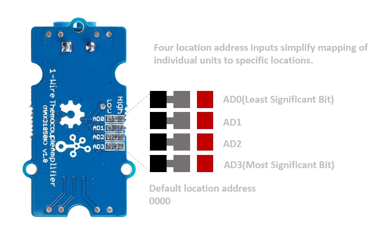
This module is based on the MAX31850K, which integrates amplifier, ADC and 64-bit ROM. Thanks to the 64-bit ROM, each device has a unique 64-bit serial code, which allows multiple units to function on the same 1-Wire bus. Therefore, it is simple to use one microcontroller (the master device) to monitor temperature from many thermocouples distributed over a large area.
Again, this module can't work alone, it must work with a k-type thermocouple, if you do not have one, you can consider Thermocouple Temperature Sensor K Type-1M in our bazaar.

Version
| Product Version | Changes | Released Date |
|---|---|---|
| Grove - 1-Wire Thermocouple Amplifier (MAX31850K) | Initial | Aug 2018 |
Features
- Integrated Cold-Junction Compensation
- Wide Conversion Range: allow readings from -270℃ to +1768℃
- 14-Bit, 0.25℃ Resolution
- Will not work with any other kind of thermocouple except K type
- Detects Thermocouple Shorts to GND or VDD
- Detects Open Thermocouple
Although this module can convert from -270℃ to +1768℃, the temperature measurment range also limited by the thermocouple you use.
Specification
| Item | Value |
|---|---|
| Operating Voltage | 3.3V/5V |
| Temperature Resolution | 14 bits |
| Temperature Accuracy | ± 2℃ |
| Operating Temperature Range | -40℃ to +125℃ |
| Allow Readings Range | -270℃ to +1768℃ |
| Storage Temperature Range | -65℃ to +150℃ |
| Input Jack | DIP Female Blue-2Pin |
| Output Interface | 1-Wire bus |
| Size | L: 40mm W: 20mm H: 18mm |
| Weight | 4.8g |
| Package size | L: 140mm W: 90mm H: 20mm |
| Gross Weight | 11g |
Applications
- Medical
- Appliances
- Industrial
- HVAC(Heating, Ventilation and Air Conditioning)
Hardware Overview
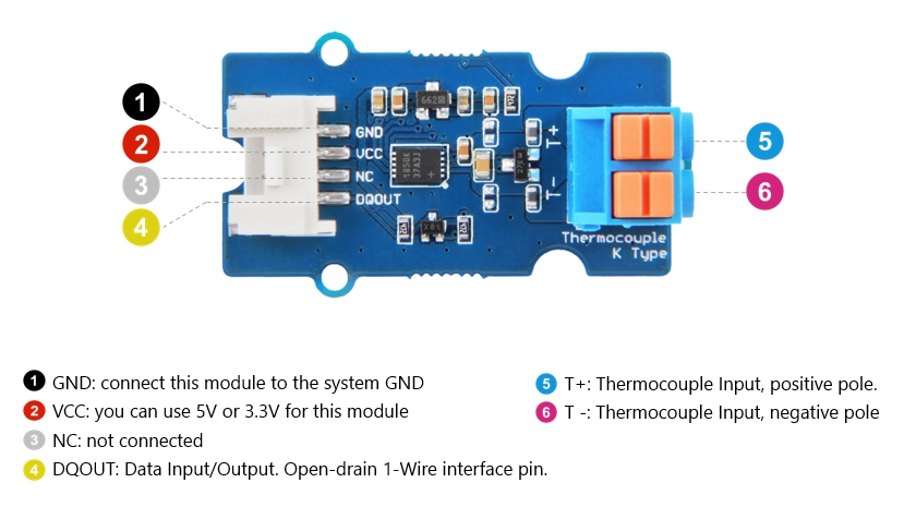
Pin Map
Schematic
Input Jack
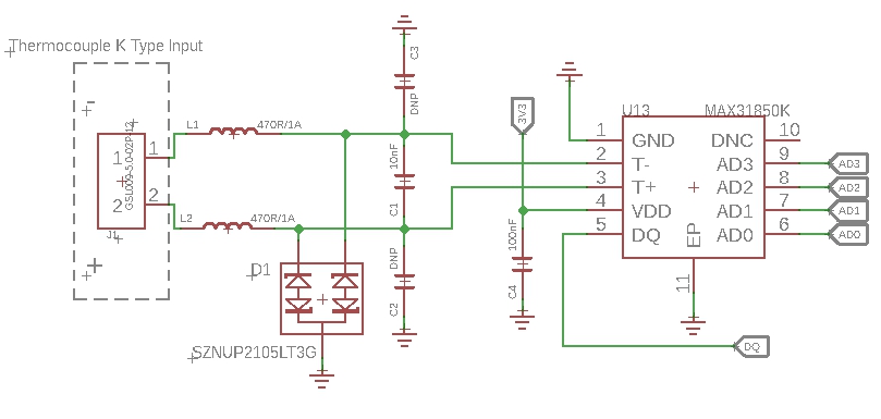
Because of the small signal levels involved, we take a lot measures to filter the noise.
1--L1,L2 We use thermocouple up to 1 meter long. Such long wires can be regarded as antennas, which will receive spatial electric field interference and generate high frequency noise. So we use two inductances to filter the high frequency noise.
2--C1 It is strongly recommended by the chip manufacturer to add a 10nF ceramic surfacemount differential capacitor, placed across the T+ and T- pins, in order to filter noise on the thermocouple lines.
3--D1 We use the SZNUP2105LT3G DUAL BIDIRECTIONAL VOLTAGE SUPPRESSOR to protect this module from ESD(Electro-Static discharge).
Bi-directional level shifter circuit

This is a typical Bi-directional level shifter circuit to connect two different voltage section. The left part, DQ pin of the MAX31850K use 3.3V, if the Arduino use 5V, this circuit will be needed. In the schematic above, Q6 is N-Channel MOSFET 2N7002, which act as a bidirectional switch. In order to better understand this part, you can refer to the AN10441.
In this section we only show you part of the schematic, for the full document please refer to the [Resources](https://wiki.seeedstudio.com/Grove-I2C_High_Accuracy_Temperature_Sensor-MCP9808/#resources)
Assembling Drawing
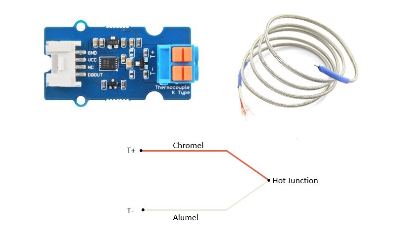
Please insert the Red wire of thermocouple into the **T+** port of the Grove - 1-Wire Themrocouple Amplifier (MAX31850K) , and the White wire into T- port. If you do not use the k-type thermocouple from our bazaar, the color may be different, please make sure the + - with the seller.
Platforms Supported
| Arduino | Raspberry Pi | |||
|---|---|---|---|---|
The platforms mentioned above as supported is/are an indication of the module's software or theoritical compatibility. We only provide software library or code examples for Arduino platform in most cases. It is not possible to provide software library / demo code for all possible MCU platforms. Hence, users have to write their own software library.
Getting Started
Play With Arduino
Hardware
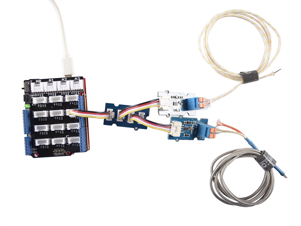
Materials required
| Seeeduino V4.2 | Base Shield | Grove - 1-Wire Thermocouple Amplifier x 2 |
|---|---|---|
 |  |  |
| Get One Now | Get One Now | Get One Now |
| k-type thermocouple x 2 | Grove - I2C Hub |
|---|---|
 |  |
| Get One Now | Get One Now |
1- We've offered two software examples, simple and multiple, the materials requirement above is for the multiple example. If you want to test the simple example, then the Grove - I2C Hub is not necessary, and only one Grove - 1-Wire Thermocouple Amplifier will be enough.
2- We use I2C Hub here not as a I2C interface, but just as a normal one-to-two transfer interface.
Step 1. Insert the red wire of k-type thermocouple into T+, insert the light white wire of k-type thermocouple into T-
Step 2. Connect the Grove - I2C Hub to the D3 port of the Base Shield.
Step 3. Plug the Grove - 1-Wire Thermocouple Amplifier A and B into the Grove - I2C Hub.
Step 4. Plug Grove - Base Shield into Seeeduino.
Step 5. Connect Seeeduino to PC via a USB cable.
If we don't have Grove Base Shield, We also can directly connect this module to Seeeduino as below.
| Seeeduino | Grove Cable | Grove - I2C Hub | Grove - 1-Wire Thermocouple Amplifier |
|---|---|---|---|
| GND | Black | G | GND |
| 5V | Red | V | VCC |
| NC | White | SDA | NC |
| D3 | Yellow | SCL | DQOUT |
Software
If this is the first time you work with Arduino, we strongly recommend you to see [Getting Started with Arduino](https://wiki.seeedstudio.com/Getting_Started_with_Arduino/) before the start
Step 1. Download the Seeed_MAX31850K Library from Github.
Step 2. Refer to How to install library to install library for Arduino.
Step 3. Unzip the library folder, follow the path to find and open Multiple.ino ---> xxxx\Arduino\libraries\Seeed_MAX31850K-master\examples\Multiple. xxxx is the path you installed your Arduino.
This folder \Arduino\libraries\Seeed_MAX31850K-master\examples contains two examples: Multiple.ino and Simple.ino.
Simple.ino--single mode(one host and one slave)
Multiple.ino--multiple mode(one host and multiple slaves,base on rom addressing-one wire search algorithm)
Or, you can just click the icon  in upper right corner of the code block to copy the following code into a new sketch in the Arduino IDE.
#include <OneWire.h>
#include <DallasTemperature.h>

// Data wire is plugged into port 2 on the Arduino
#define ONE_WIRE_BUS 3
#define TEMP_RESOLUTION 9

#define MAX_NUM_OF_DEVICE  10

// Setup a oneWire instance to communicate with any OneWire devices (not just Maxim/Dallas temperature ICs)
OneWire oneWire(ONE_WIRE_BUS);

// Pass our oneWire reference to Dallas Temperature.
DallasTemperature sensors(&oneWire);

// arrays to hold device addresses
DeviceAddress Device_add[MAX_NUM_OF_DEVICE];
DeviceAddress insideThermometer, outsideThermometer;

void setup(void)
{
  // start serial port
  Serial.begin(115200);
  Serial.println("Dallas Temperature IC Control Library Demo");

  // Start up the library
  sensors.begin();

  // locate devices on the bus
  Serial.print("Locating devices...");
  Serial.print("Found ");
  Serial.print(sensors.getDeviceCount(), DEC);
  Serial.println(" devices.");

  Serial.print("Parasite power is: ");
  if (sensors.isParasitePowerMode()) Serial.println("ON");
  else Serial.println("OFF");

  for(int i=0;i<sensors.getDeviceCount();i++)
  {
    if(!sensors.getAddress(Device_add[i],i))
    {
      Serial.println("Find device error!!");
    }
    else
    {
      Serial.print("Device [");
      Serial.print(i);
      Serial.print("] addr =");
      printAddress(Device_add[i]);
    }
    Serial.println(" ");
  }

}

// function to print a device address
void printAddress(DeviceAddress deviceAddress)
{
  for (uint8_t i = 0; i < 8; i++)
  {
    // zero pad the address if necessary
    if (deviceAddress[i] < 16) Serial.print("0");
    Serial.print(deviceAddress[i], HEX);
  }
}

// function to print the temperature for a device
void printTemperature(DeviceAddress deviceAddress)
{
  float tempC = sensors.getTempC(deviceAddress);
  Serial.print("Temp C: ");
  Serial.print(tempC);
  Serial.print(" Temp F: ");
  Serial.print(DallasTemperature::toFahrenheit(tempC));
}

// function to print a device's resolution
void printResolution(DeviceAddress deviceAddress)
{
  Serial.print("Resolution: ");
  Serial.print(sensors.getResolution(deviceAddress));
  Serial.println();
}

// main function to print information about a device
void printData(DeviceAddress deviceAddress)
{
  Serial.print("Device Address: ");
  printAddress(deviceAddress);
  Serial.print(" ");
  printTemperature(deviceAddress);
  Serial.println();
}

void loop(void)
{
  // call sensors.requestTemperatures() to issue a global temperature
  // request to all devices on the bus
  Serial.print("Requesting temperatures...");
  sensors.requestTemperatures();
  Serial.println("DONE");

  for(int i=0;i<sensors.getDeviceCount();i++)
  {
     printData(Device_add[i]);
  }

}
Step 4. Upload the demo. If you do not know how to upload the code, please check How to upload code.
Step 5. Open the Serial Monitor of Arduino IDE by click Tool-> Serial Monitor. Or tap the ++ctrl+shift+m++ key at the same time. Then set the baud rate 115200.
If every thing goes well, you will get the result.
DONE
Device Address: 3B23211800ing temperatures... 77.00
Requesting temperatures...DONE
Device Address: 3B2321180000005C Temp C: 25.00 Temp F: 77.00
Requesting temperatures...Dallas Temperature IC Control Library Demo
Locating devices...Found 2 devices.
Parasite power is: OFF
Device [0] addr =3B4C965D06D80C98
Device [1] addr =3B2321180000005C
Requesting temperatures...DONE
Device Address: 3B4C965D06D80C98 Temp C: 26.25 Temp F: 79.25
Device Address: 3B2321180000005C Temp C: 25.25 Temp F: 77.45
Requesting temperatures...DONE
Device Address: 3B4C965D06D80C98 Temp C: 26.25 Temp F: 79.25
Device Address: 3B2321180000005C Temp C: 25.00 Temp F: 77.00
Requesting temperatures...DONE
Device Address: 3B4C965D06D80C98 Temp C: 26.25 Temp F: 79.25
Device Address: 3B2321180000005C Temp C: 25.25 Temp F: 77.45
Requesting temperatures...DONE
Device Address: 3B4C965D06D80C98 Temp C: 26.00 Temp F: 78.80
Device Address: 3B2321180000005C Temp C: 25.25 Temp F: 77.45
Requesting temperatures...DONE
Device Address: 3B4C965D06D80C98 Temp C: 26.00 Temp F: 78.80
Device Address: 3B2321180000005C Temp C: 25.25 Temp F: 77.45
Schematic Online Viewer
Resources
- [Zip] Grove - 1-Wire Thermocouple Amplifier eagle files
- [Zip] Seeed_MAX31850K Library
- [PDF] Datasheet of MAX31850
Tech Support & Product Discussion
Upgradable to Industrial Sensors
With the SenseCAP S2110 controller and S2100 data logger, you can easily turn the Grove into a LoRaWAN® sensor. Seeed not only helps you with prototyping but also offers you the possibility to expand your project with the SenseCAP series of robust industrial sensors.
The IP66 housing, Bluetooth configuration, compatibility with the global LoRaWAN® network, built-in 19 Ah battery, and powerful support from APP make the SenseCAP S210x the best choice for industrial applications. The series includes sensors for soil moisture, air temperature and humidity, light intensity, CO2, EC, and an 8-in-1 weather station. Try the latest SenseCAP S210x for your next successful industrial project.