Grove - Rotary Angle Sensor
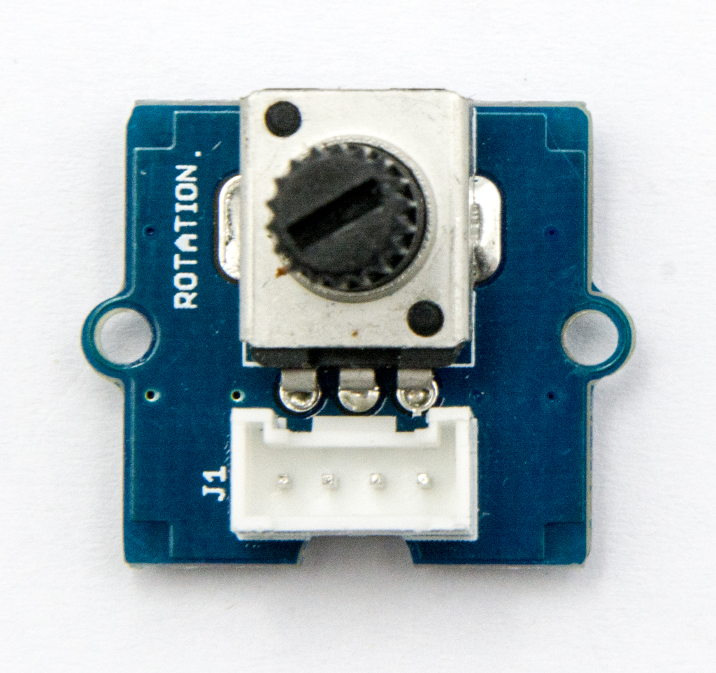
The rotary angle sensor produces analog output between 0 and Vcc (5V DC with Seeeduino) on its D1 connector. The D2 connector is not used. The angular range is 300 degrees with a linear change in value. The resistance value is 10k ohms, perfect for Arduino use. This may also be known as a “potentiometer ”.
![]()
There is another product, Grove - Rotary Angle Sensor(P). What does “P” mean? “P” is for “panel mount” in this product.It is the sister version of Grove - Rotary Angle Sensor. They are identical except the Grove connecter is moved to the back so that you can easily use it as a neat and wire-free human interface device.
 |  |
![]()
Version
| Product Version | Changes | Released Date |
|---|---|---|
| Grove-Rotary Angle Sensor(P) V1.1 | Initial | Jan 2013 |
| Grove-Rotary Angle Sensor V1.2 | Initial | May 2014 |
Features
- Grove Interface
- Easy to Use
- Grove Base Module
More details about Grove modules please refer to Grove System
Specifications
| Item | Min | Typical | Max | Unit |
|---|---|---|---|---|
| Voltage | 4.75 | 5.0 | 5.25 | VDC |
| Rotary Angle | 0 | / | 300 | Deg |
| Dimension | / | 19x19x30.1 | / | mm |
Platforms Supported
| Arduino | Raspberry Pi | |||
|---|---|---|---|---|
The platforms mentioned above as supported is/are an indication of the module's software or theoritical compatibility. We only provide software library or code examples for Arduino platform in most cases. It is not possible to provide software library / demo code for all possible MCU platforms. Hence, users have to write their own software library.
Getting Started
If this is the first time you work with Arduino, we firmly recommend you to see Getting Started with Arduino before the start.
Play With Arduino
Hardware
- Step 1. Prepare the below stuffs:
| Seeeduino V4.2 | Base Shield | Grove-Rotary Angle Sensor | Grove-LED |
|---|---|---|---|
 |  |  |  |
| Get One Now | Get One Now | Get One Now | Get One Now |
- Step 2. Connect Grove-Rotary Angle Sensor to A0 port of Grove-Base Shield.
- Step 3. Connect Grove-LED to D3 port of Grove-Base Shield.
- Step 4. Plug Grove - Base Shield into Seeeduino.
- Step 5. Connect Seeeduino to PC via a USB cable.

If we don't have Grove Base Shield, We also can directly connect Grove-Rotary Angle Sensor and Grove-Led to Seeeduino as below. Grove-Led must be connected to PWM port. For Seeeduino, they are D3,5,6,9,10,11.
| Seeeduino | Grove-Rotary Angle Sensor | Seeeduino | Grove-LED |
|---|---|---|---|
| 5V | Red | 5V | Red |
| GND | Black | GND | Black |
| NC | White | NC | White |
| A0 | Yellow | D3 | Yellow |
Software
- Step 1. Please copy below code to Arduio IDE and upload to arduino. If you do not know how to upload the code, please check how to upload code.
/*macro definitions of Rotary angle sensor and LED pin*/

#define ROTARY_ANGLE_SENSOR A0
#define LED 3  //the Grove - LED is connected to PWM pin D3 of Arduino
#define ADC_REF 5 //reference voltage of ADC is 5v.If the Vcc switch on the seeeduino
                    //board switches to 3V3, the ADC_REF should be 3.3
#define GROVE_VCC 5 //VCC of the grove interface is normally 5v
#define FULL_ANGLE 300 //full value of the rotary angle is 300 degrees

void setup()
{
    Serial.begin(9600);
    pinMode(ROTARY_ANGLE_SENSOR, INPUT);
    pinMode(LED,OUTPUT);
}

void loop()
{
    float voltage;
    int sensor_value = analogRead(ROTARY_ANGLE_SENSOR);
    voltage = (float)sensor_value*ADC_REF/1023;
    float degrees = (voltage*FULL_ANGLE)/GROVE_VCC;
    Serial.println("The angle between the mark and the starting position:");
    Serial.println(degrees);

    int brightness;
    brightness = map(degrees, 0, FULL_ANGLE, 0, 255);
    analogWrite(LED,brightness);
    delay(500);
}
- Step 2. Adjust Grove-Rotary Angle Sensor and we will see the Grove-LED changes the brightness.
Play with Codecraft
Hardware
Step 1. Connect a Grove - Rotary Angle Sensor to port A0, and connect a Grove - Red LED to port D3 of a Base Shield.
Step 2. Plug the Base Shield to your Seeeduino/Arduino.
Step 3. Link Seeeduino/Arduino to your PC via an USB cable.
Software
Step 1. Open Codecraft, add Arduino support, and drag a main procedure to working area.
If this is your first time using Codecraft, see also Guide for Codecraft using Arduino.
Step 2. Drag blocks as picture below or open the cdc file which can be downloaded at the end of this page.

Upload the program to your Arduino/Seeeduino.
When the code finishes uploaded, the brightness of the LED will vary depending on the angle of the sensor, and the angle value displayed in the Serial Monitor.
Play With Raspberry Pi (With Grove Base Hat for Raspberry Pi)
Hardware
- Step 1. Things used in this project:
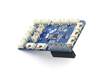
| Raspberry pi | Grove Base Hat for RasPi | Grove - Rotary Angle Sensor |
|---|---|---|
 |  | |
| Get ONE Now | Get ONE Now | Get ONE Now |
- Step 2. Plug the Grove Base Hat into Raspberry.
- Step 3. Connect the rotary sensor to port A0 of the Base Hat.
- Step 4. Connect the Raspberry Pi to PC through USB cable.

For step 3 you are able to connect the rotary angle sensor to any Analog Port but make sure you change the command with the corresponding port number.
Software
If you are using Raspberry Pi with Raspberrypi OS >= Bullseye, you have to use this command line only with Python3.
- Step 1. Follow Setting Software to configure the development environment.
- Step 2. Download the source file by cloning the grove.py library.
cd ~
git clone https://github.com/Seeed-Studio/grove.py
- Step 3. Excute below commands to run the code.
cd grove.py/grove
python3 grove_rotary_angle_sensor.py 0
Following is the grove_rotary_angle_sensor.py code.
import math
import sys
import time
from grove.adc import ADC


class GroveRotaryAngleSensor(ADC):
    def __init__(self, channel):
        self.channel = channel
        self.adc = ADC()

    @property
    def value(self):
        return self.adc.read(self.channel)


Grove = GroveRotaryAngleSensor


def main():
    if len(sys.argv) < 2:
        print('Usage: {} adc_channel'.format(sys.argv[0]))
        sys.exit(1)

    sensor = GroveRotaryAngleSensor(int(sys.argv[1]))

    while True:
        print('Rotary Value: {}'.format(sensor.value))
        time.sleep(.2)


if __name__ == '__main__':
    main()
If everything goes well, you will be able to see the following result
pi@raspberrypi:~/grove.py/grove $ python3 grove_rotary_angle_sensor.py 0
Rotary Value: 932
Rotary Value: 931
Rotary Value: 931
Rotary Value: 931
Rotary Value: 933
Rotary Value: 931
Rotary Value: 742
Rotary Value: 666
Rotary Value: 666
Rotary Value: 549
Rotary Value: 520
Rotary Value: 499
Rotary Value: 430
Rotary Value: 430
Rotary Value: 321
Rotary Value: 286
Rotary Value: 205
Rotary Value: 127
Rotary Value: 88
Rotary Value: 0
Rotary Value: 0
Rotary Value: 0
Rotary Value: 0
Rotary Value: 0
Rotary Value: 0
Rotary Value: 0
^CTraceback (most recent call last):
  File "grove_rotary_angle_sensor.py", line 66, in <module>
    main()
  File "grove_rotary_angle_sensor.py", line 62, in main
    time.sleep(.2)
KeyboardInterrupt
You can quit this program by simply press ++ctrl+c++.
You may have noticed that for the analog port, the silkscreen pin number is something like A0, A1, however in the command we use parameter 0 and 1, just the same as digital port. So please make sure you plug the module into the correct port, otherwise there may be pin conflicts.
Play With Raspberry Pi (with GrovePi_Plus)
Hardware
- Step 1. Prepare the below stuffs:
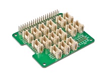
| Raspberry pi | GrovePi_Plus | Grove-Rotary Angle Sensor | Grove-LED |
|---|---|---|---|
|  | | |
| Get ONE Now | Get ONE Now | Get One Now | Get One Now |
- Step 2. Plug the GrovePi_Plus into Raspberry.
- Step 3. Connect Grove-Rotary Angle Sensor to A0 port of GrovePi_Plus.
- Step 4. Connect Grove-LED to D5 port of GrovePi_Plus.
- Step 5. Connect the Raspberry to PC through USB cable.

Software
If you are using Raspberry Pi with Raspberrypi OS >= Bullseye, you have to use this command line only with Python3.
- Step 1. Follow Setting Software to configure the development environment.
- Step 2. Git clone the Github repository.
cd ~
git clone https://github.com/DexterInd/GrovePi.git
- Step 3. Excute below commands to monitor the loudness.
cd ~/GrovePi/Software/Python
python3 grove_rotary_angle_sensor.py
Here is the grove_rotary_angle_sensor.py code.
import time
import grovepi

# Connect the Grove Rotary Angle Sensor to analog port A0
# SIG,NC,VCC,GND
potentiometer = 0

# Connect the LED to digital port D5
# SIG,NC,VCC,GND
led = 5

grovepi.pinMode(potentiometer,"INPUT")
grovepi.pinMode(led,"OUTPUT")
time.sleep(1)

# Reference voltage of ADC is 5v
adc_ref = 5

# Vcc of the grove interface is normally 5v
grove_vcc = 5

# Full value of the rotary angle is 300 degrees, as per it's specs (0 to 300)
full_angle = 300

while True:
    try:
        # Read sensor value from potentiometer
        sensor_value = grovepi.analogRead(potentiometer)

        # Calculate voltage
        voltage = round((float)(sensor_value) * adc_ref / 1023, 2)

        # Calculate rotation in degrees (0 to 300)
        degrees = round((voltage * full_angle) / grove_vcc, 2)

        # Calculate LED brightess (0 to 255) from degrees (0 to 300)
        brightness = int(degrees / full_angle * 255)

        # Give PWM output to LED
        grovepi.analogWrite(led,brightness)

        print("sensor_value = %d voltage = %.2f degrees = %.1f brightness = %d" %(sensor_value, voltage, degrees, brightness))
    except KeyboardInterrupt:
        grovepi.analogWrite(led,0)
        break
    except IOError:
        print ("Error")
- Step 4. Adjust Grove-Rotary Angle Sensor and we will see the Grove-LED changes the brightness.
Play with TI LaunchPad
Reading the Potentiometer (Rotary Angle Sensor)
This example shows how to read the analog output coming from the Grove potentiometer module. We will be combining a few Grove modules in this example! By turning the potentiometer knob, we will display the analog reading value on the Grove 4-digital display.

/*
    Rotary Angle Sensor
    Demonstrates analog input by reading an analog sensor on J16 of the Grove Base BoosterPack. The speed of the red LED on the LaunchPad will change depending on the position of the potentiometer knob. This example will also display the analog reading value on the Grove 4-digital display.

    The circuit:
    * Potentiometer attached to pin 24 (J6 on Grove Base BoosterPack)
    * center pin of the potentiometer to the analog pin
    * one side pin (either one) to ground
    * the other side pin to VCC (3.3V)

    * Note: Because of unstable of the voltage, the value of the rotary angle sensor
            varies slightly from run to run even you don't touch it.

    Created by Oliver Wang

    This example code is in the public domain.

    https://www.seeedstudio.com/wiki/GROVE_-_Starter_Kit_v1.1b#Grove_-_Rotary_Angle_Sensor
    */

#include "TM1637.h"

/* Macro Define */
#define CLK               39                  /* 4-digital display clock pin */
#define DIO               38                /* 4-digital display data pin */
#define ROTARY_ANGLE_P    24               /* pin of rotary angle sensor */

/* Global Variables */
TM1637 tm1637(CLK, DIO);                  /* 4-digital display object */
int analog_value = 0;                     /* variable to store the value coming from rotary angle sensor */

int8_t bits[4] = {0};                     /* array to store the single bits of the value */

/* the setup() method runs once, when the sketch starts */
void setup() {

    /* Initialize 4-digital display */
    tm1637.init();
    tm1637.set(BRIGHT_TYPICAL);

}

/* the loop() method runs over and over again */
void loop() {

    analog_value = analogRead(ROTARY_ANGLE_P);      /* read the value from the sensor */
    memset(bits, 0, 4);                             /* reset array when we use it */
    for(int i = 3; i >= 0; i--) {
        /* get single bits of the analog value */
        bits[i] = analog_value % 10;
        analog_value = analog_value / 10;
        tm1637.display(i, bits[i]);                 /* display by 4-digital display */
    }
    delay(100);
}
Grove - Rotary Angle Sensor(P) v1.1 Schematic File
Grove-Rotary Angle Sensor v1.2 Schematic File
Resources
- [Eagle&PDF] Grove-Rotary Angle Sensor v1.2 Schematic File
- [Eagle&PDF] Grove - Rotary Angle Sensor(P) v1.1 Schematic File
- [Library] Github repository for Rotary Angle Sensor
- [Codecraft] CDC File
Projects
Using Grove-Rotary Angle Sensor(P) to Control Grove LED: Using Arduino/Genuino 101 to control the brightness of an LED through Grove-Rotary Angle Sensor(P).
Rotary Angle Grove module:
Tech Support & Product Discussion
Thank you for choosing our products! We are here to provide you with different support to ensure that your experience with our products is as smooth as possible. We offer several communication channels to cater to different preferences and needs.