Grove Lightning Sensor AS3935
Introduction
The Grove Lightning Sensor is a highly sensitive sensor that detects electric fields free in air and using an internal proprietary algorithm determines if it is caused by the front end of a storm with lightning events. It is very easy to be used as a plug and play device using the Grove standard cable can accept several adjustments to be optimized for the application environment, both indoor or outdoor.
The use is for preventive alert on incoming lightning front of a storm so to avoid injuries to electrical equipment or human and for weather research because can furnish several data on the strength and number of events. This sensor can be fully integrated with other sensors in a forecast weather station and be very useful in agriculture for crop protection in case of incoming storms. Can detect the lightning front of a storm up to 30 – 40 km distance, when is still out of sight.
Features
Extremely compact and easy to use sensor.
Very sensitive to electric fields in air selects only ones that meet the wave form typical of lightning front, other are rejected.
Communication trough I2C protocol with easy interface to Arduino, Seeeduino or Raspberry Pi development boards.
Extremely low consumption, can go in sleep mode to reduce consume and Prolong battery life.
Sends out on an IRQ pin the interrupt signal any time a lightning front is validated. Useful for micro-controller connection and software control.
Grove system fully compatible interface.
Easy integration in weather station or alerting devices to prevent injuries in electronic equipment or humans.
Hardware Overview
Before everything starts, it is quite essential to have some basic parameters of the product. The following table provides information about the characteristics of Grove Lightning Sensor.
Specifications
| Parameter | Range/Value |
|---|---|
| Input Voltage | 5 Volt or 3.3 Volt (select appropriate solder pads) |
| Communication | I2C standard, SPI using the provided output |
| Maximum detection range | 40 km |
| Programmable | Yes, appropriate registers can be programmed to fit the application and environment where the sensor is mounted. |
Getting Started
Module power supply selection
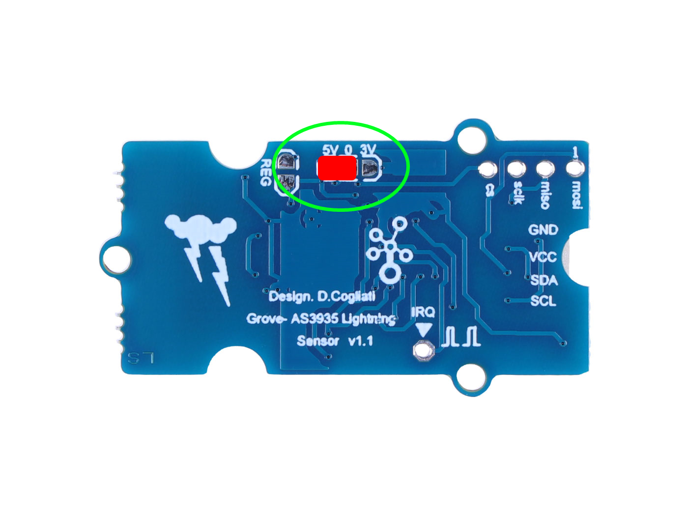
The Grove Lightning Sensor supports two different supply voltages - 5V and 3.3V. You will need to determine your supply voltage and perform simple soldering before using the module.
If you choose for the 5 Volt supply then solder pads (5V) and (0) on the Grove Lightning Sensor together as picture below.
If you choose for the 3.3 Volt supply then solder pads on the Grove Lightning Sensor together as picture below. This is the case if you are using the Seeed Arduino Breakout for Linkt Smart 7688 Duo board that works at 3.3 Volt.
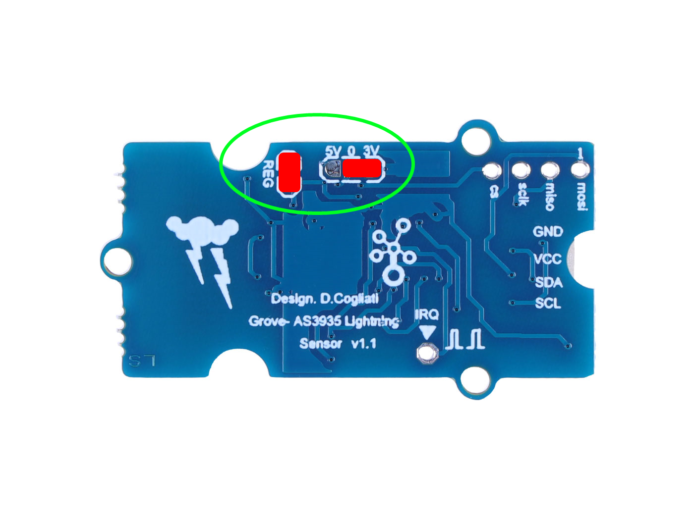
The Grove Lightning Sensor can withstand a hot swap insertion with the boards supply ON but this is not recommended, always turn off supply before connecting the Grove Lightning Sensor to the board connector.
Arduino Example
The Arduino code here furnished permits to dialog with the sensor and to modify all the relevant registers which determines the best behaviour during operation. The sensor is furnished with base values in registers as well described in the code, and this is a good starting point for application. Some work is necessary to get the best fit to application and this is a very challenging job working with the sensor, because shows extremely adaptable to the environment where is used.
Step 1. Launch the Arduino application.
Step 2. Select your development board model and add it to the Arduino IDE.
If you want to use Seeeduino for the later routines, please refer to this tutorial to finish adding.
If you want to use Seeed Studio XIAO SAMD21 for the later routines, please refer to this tutorial to finish adding.
If you want to use Seeed Studio XIAO RP2040 for the later routines, please refer to this tutorial to finish adding.
If you want to use Seeed Studio XIAO nRF52840 for the later routines, please refer to this tutorial to finish adding.
If you want to use Seeed Studio XIAO ESP32C3 for the later routines, please refer to this tutorial to finish adding.
Demo: Using Grove Lightning Sensor on the Seeeduino
Materials Required
| Seeeduino V4.3 | Grove - Lightning Sensor AS3935 |
|---|---|
 | |
| Get ONE Now | Get ONE Now |
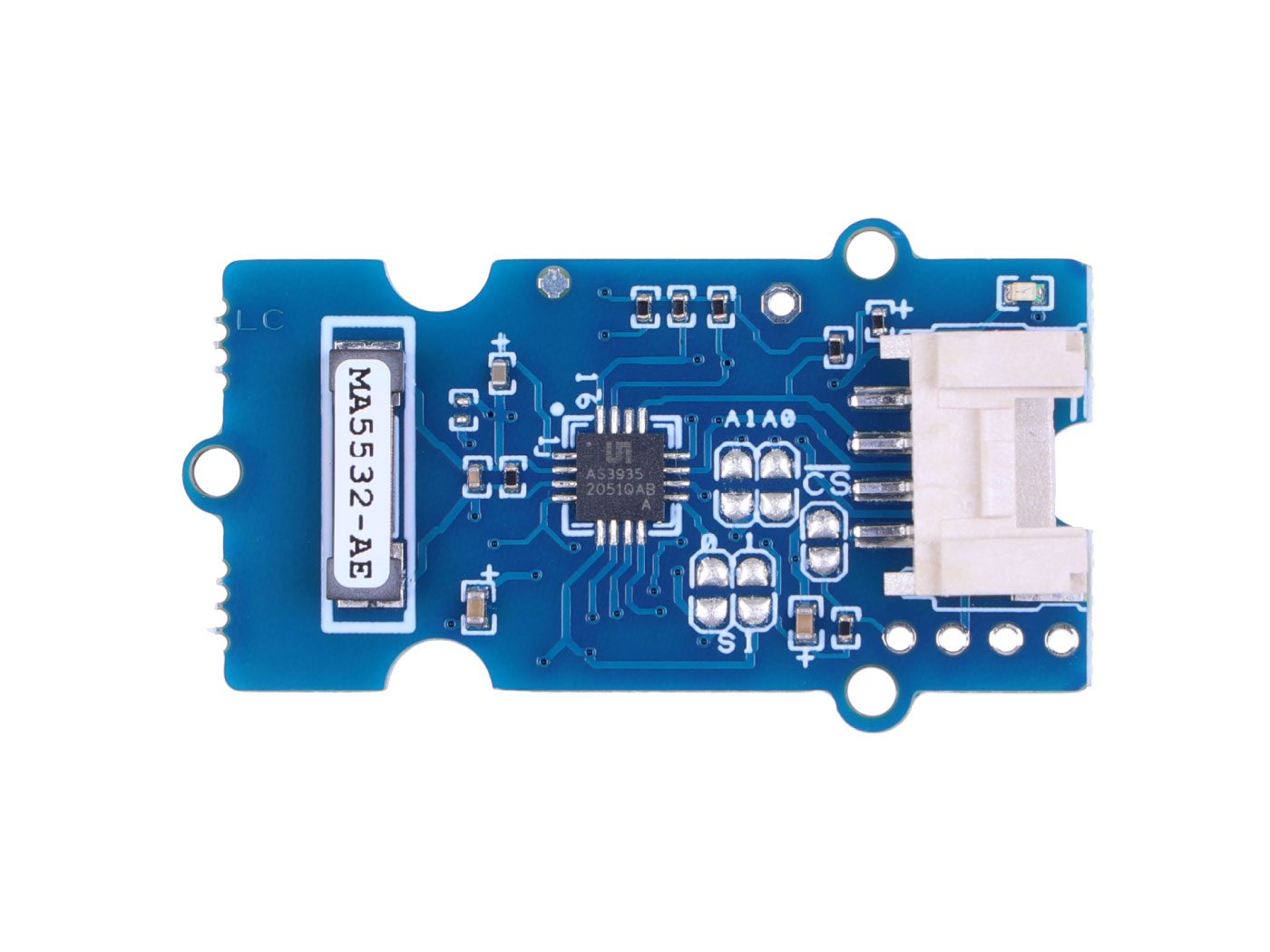
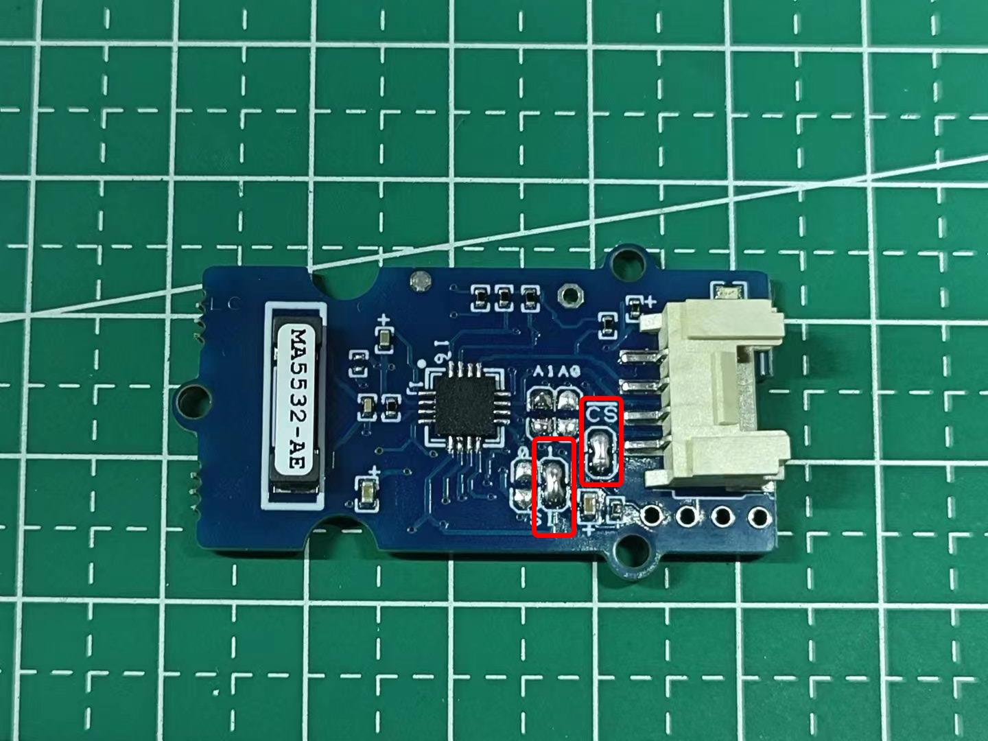
Please check that the front pads of the sensor have been soldered before use. If the position indicated in the picture is not soldered, you may experience problems with the IIC device not being detected when executing the programme later.
Step 3. Connect Grove Lightning Sensor to port I2C of Seeeduino V4.
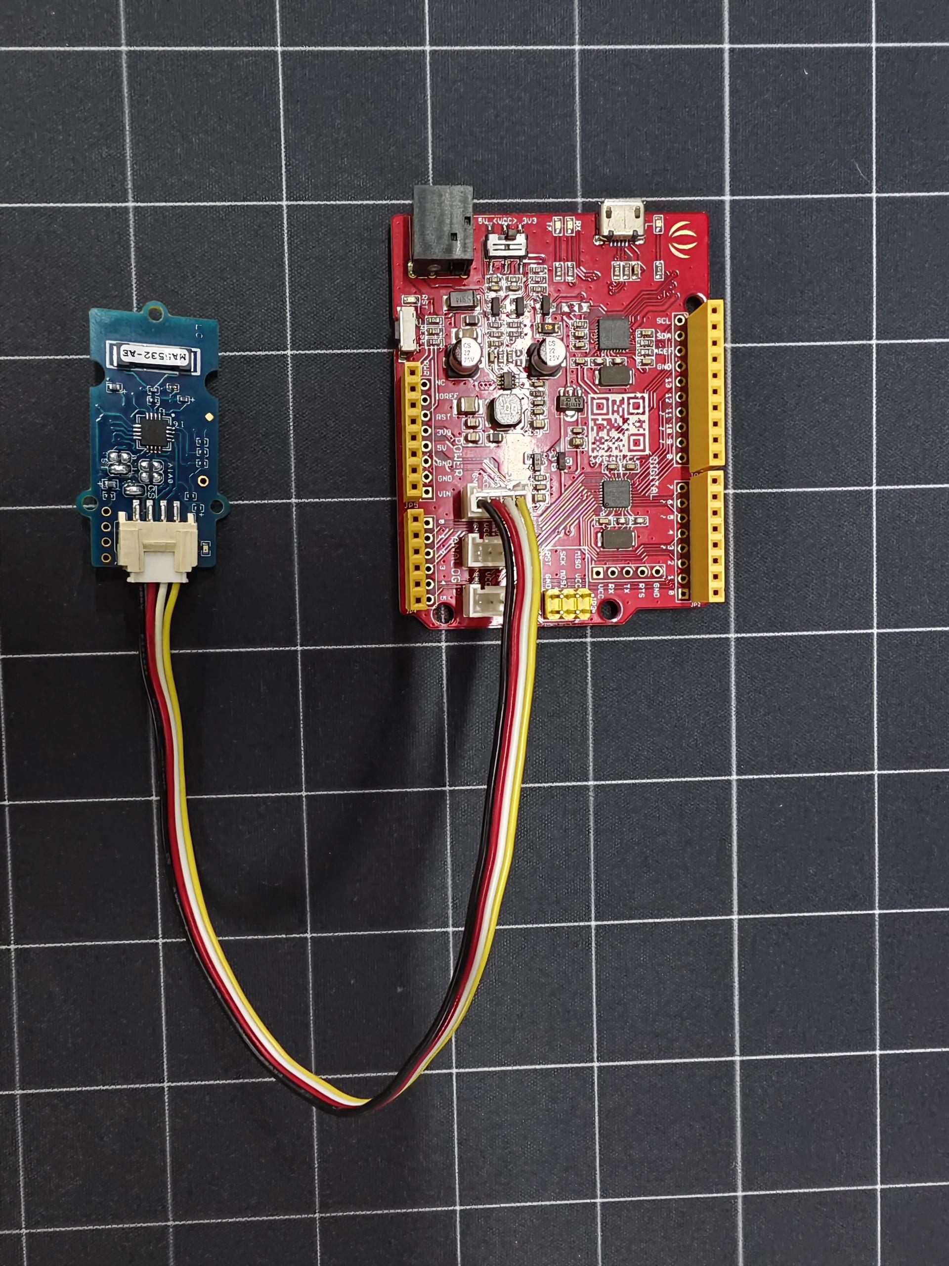
Step 4. Connect Seeeduino to PC via a Micro-USB cable.
Step 5. Upload the following program to Seeeduino.
Click here to preview the full code
//*********************************************************************************
//*************** Designed for Seeed Grove sensor developments *******************
//*************** GROVE FRANKLYN LIGHTNING SENSOR AS3935 *******************
//*************** front of lightning fall detection sensor *******************
//*************** *******************
//*************** first release: 1.0 - 10/15/2022 *******************
//*************** Author: Davide Cogliati *******************
//*********************************************************************************
//
//Abstract on the work:
//------------------------------------------------------------------------------------------------------
//This GROVE Sensor board integrates the AS3935 a programmable fully integrated Lightning
//Sensor IC that detects the approach of lightning activity in the vicinity and provides an
//estimation of distance to the head of the storm. In the AS3935 there is an embedded lightning
//algorithm that checks the incoming signal form during time and rejects the potential man-made
//disturbers as false alarms.
//The AS3935 can also provide information on the noise level and inform the external microcontroller
//in case of high noise conditions, with the noise floor generator and noise floor evaluation blocks.
//These latter functions are programmable via the internal registers to optimize the working on
//field of the sensor itself (INDOOR, OUTDOOR).
//The AS3935 can be programmed via I²C or a 4-wire standard SPI. Also along with I²C it is possible to
//choose among three different addresses (0X01, 0X02, 0X03). Two clocks are internally generated by two different
//RC-Oscillators: TRCO and SRCO and an automatic calibration procedure can be run on command to increase the
//precision of those oscillators any time the sensor is turned ON.
//The board can be supplied by 5 Volt or by an internal 3.3 Volt voltage regulator by choosing the correct settings
//by jumper on the board.
//The board results very sensitive to electromagnetic fields so accidental peaks or false lightnings can be
//revealed, of course the setup of the internal registers can optimize the false triggering events.
//If a microprocessor is connected to the board via the I²C bus and the IRQ pin provided on the board the
//lightning alarms can be managed in the best way achieving also a filtering on the events writing an
//appropriate algorithm.
//This board was tested connecting an oscilloscope on the IRQ pin output and running the SERIAL PLOTTER & SERIAL
//MONITOR of ARDUINO GUI then simulating disturbing actions or simulating lightning so to make the device
//trigger as appropriate.
//Analisis of the experimental result show an extreme sensitivity to events and capability of the internal
//firmware of the AS3935 to capture disturbance or simulated lightnings. Of course during test, modification
//of the internal registers was done in order to watch how the response changed.
//
//-----------------------------------------------------------------------------------------------------
//Sketch philosophy: ---------------------------------------------------------------
//-----------------------------------------------------------------------------------------------------
//This sketch has been designed to give an easy way to get working with the AS3935
//Grove sensor with all in a sketch. This sketch is an example on how to work out
//the sensor functionality in direct way, optimizing the register contents to influence
//the final behaviour of the sensor. Working with this sketch let you manage also in
//way the data ouput that can be in plain text form using the SERIAL MONITOR or in a
//graphical way using the SERIAL PLOTTER in the ARDUINO GUI.
//Only 1 library is needed, the "#include <Wire.h> //FOR I2C MODE COMUNICATION BUS" in order
//to make all very simple, all other Software features are written by hand.
//
//This sketch provides testing of sensor internal registers and an I2C Device Address identification
//routine to test the board soldering A0, A1 taps in order to change device address.
//This sketch doesn't manage the SPI functionality communication port but the the I2C port
//which is the GROVE standard. To work with the SPI port some jumper and soldering taps are
//provided on the board (SI tap) and a 4 way connector pads for SPI connection are
//placed on one side of the board.
//
//This board can work at 5.0 Volt or 3.3 Volt supply to optimize the interfacing to the
//microcontroller supply voltage. To choose one or the other supply a system of easy
//jumper selection is provided on the board, the Standard supply is 5.0 Volt.
//If the SPI communication port will be used the communication instructions of these sketch
//should be modified so to use SPI instead of I2C and the ARDUINO
//free "#include <SPI.h> //FOR SPI MODE COMUNICATION BUS" is to be put instead of the
//"#include <Wire.h>".
//This sketch is to get quickly using the sensor AS3935 without boring on many features
//to understand, but of course all necessary modification can be made to adapt it to final
//use in application.
//----------------------------------------------------------------------------------------------------
//
//********************************************************************************
//********************************************************************************
//********************************************************************************
#include <Wire.h> //FOR I2C MODE COMUNICATION BUS
//------------------------------------------------------------------------------------------------
//bit0= 0 0= power ON ------> SET THIS MANUALLY to POWER OFF STATE the SENSOR !!!
// 1= power OFF
//bit 1..5= AFE (gain) = 10010 (default value)
//Indoor 10010 suggested
//Outdoor 01110 suggested
//-----------------------------------------------------------------------------------------------
#define INDOOR 0b00100100 //power ON bit0= 0
#define OUTDOOR 0b00011100 //power ON bit0= 0
//-----------------------------------------------------------------------------------------------
#define DIRECT_COMMAND 0x96 //write this value in the following registers to operate a command
//---------------------------------
// Action REGISTER
//---------------------------------
// PRESET_DEFAULT 0x3C
// CALIB_RCO 0x3D
//---------------------------------
//--------------------------------------------------
//global variables
//--------------------------------------------------
char REG0X02reset_startup ; //this is used during resetting STATISTICAL in working operation
char REG0X02reset_startup_up ; //this is used to start up the sensor
char REG0X02reset_startup_down ; //this is used to start down the sensor
//-----------------------------------------------------------------------------
//VERY IMPORTANT TO SEE RESULTS OUTPUT WITH ARDUINO SERIAL -----------
//-----------------------------------------------------------------------------
//SET THE DISPLAY MODE WITH ARDUINO:
//select directly in ARDUINO GUI for "SERIAL MONITOR" or "SERIAL PLOTTING"
//----------------------------------------------------------------------------
//+) serial monitor = data flow in legible format and variables readout
//+) serial plotting = show plotting of lightning events and other variables
//--------------------------------------------------------------------------------------------------------
char LITERAL_mode =1; //0= no print data in SERIAL MONITOR, 1= yes print data on SERIAL MONITOR
char GRAPH_mode =0; //0= no graphical data in SERIAL PLOTTER, 1= yes graphical data SERIAL PLOTTER
//--------------------------------------------------------------------------------------------------------
//--------------------------------------------------------------------------------
//I2C ADDRESS SCANNER - FINDER |
//---------------------------------------
//checks the presence of a valid AS3935 sensor online (this part can be omitted
//in final application but use it during setting up for first time the I2C address
//----------------------------------------------------------------------------------
void setup()
{
Serial.begin(9600);
if (LITERAL_mode ==1)
{
Serial.println("AS3935 LIGHTNING SENSOR| i2C SCANNER");
Serial.println("Starting....");
Serial.println("------------------------------------");
delay(1000);
}
Wire.begin();
Wire.setClock(100000); // set I2C speed
}
//------------------------------------------------------------------------------------
//------------------------------------------------------------------------------------
void loop()
{
int c;
int indevice; //device number I2C address, in final application you can assign
//directly the address (for example: indevice = 3;)
//---------------------------------------------------
// read/write functions for I2C mode:
//---------------------------------------------------
//**************************************************************************
//**************************************************************************
int done =1; //flag to start self test on I2C sensor address
indevice = 0; //reset address value
while (done)
{
indevice = indevice +1 ;
if (indevice > 7)
indevice=0;
Wire.requestFrom(indevice, 1); // Request 1 bytes from slave device
if (LITERAL_mode ==1)
{
Serial.print("scanning device = 0x0"); // Print the character
Serial.print(indevice);
Serial.println(" ");
}
delay(250);
//-----------------------------------------------------------
// SCANNED & FOUNF VALID ADDRESS SHOWING REGISTER CONTENT
//-----------------------------------------------------------
//-----------------------------------------------------------
while(Wire.available())
{
c = Wire.read(); // Receive a byte as character
if (LITERAL_mode ==1)
{
Serial.println();
Serial.print("data=.......... valid address .................. "); // Print the character RECEIVED
Serial.println();
Serial.print("found ADDR: 0X0");
Serial.print(indevice);
Serial.print(" --> answer: ");
Serial.print("[ ");
Serial.print((int)c); // Print the character
Serial.print(" ]");
}
//-------------------------------------------------------------------------------------------------
//registers FOR SETTING I2C ADDRESS: A0 & A1 using the soldering TAPS on the GROVE SENSOR A0, A1
//-------------------------------------------------------------------------------------------------
//A0 A1 ADR 0X0
//****************************************************
//SOLDER SOLDER < NOT ALLOWED !!!!> *****
//SOLDER NO 0X01 ;SOLDER TAP A0 *****
//NO SOLDER 0X02 ;SOLDER TAP A1 *****
//NO NO 0X03 ;NO SOLDERED TAPS *****
//----------------------------------------------------
//--------------------------------------------------------------------------------------------
//LIST OF THE SETUP AND RESULT REGISTERS OF THE AS3935 --------------------------------
//--------------------------------------------------------------------------------------------
//AS3935_REGISTER_NAMES | write=W / read=R | reserved bits = x, modifiable bits= a
//--------------------------------------------------------------------------------------------
// AFE_GAIN = 0x00 W/R > XXaa aaaa
// THRESHOLD, = 0X01 W/R > aaaa aaaa
// LIGHTNING_REG = 0X02 W/R > Xaaa aaaa
// INT_MASK_ANT = 0X03 W/R > aaaa Xaaa
// ENERGY_LIGHT_LSB = 0X04 R > -
// ENERGY_LIGHT_MSB = 0X05 R > -
// ENERGY_LIGHT_MMSB = 0X06 R > -
// DISTANCE = 0X07 R > -
// DISP /TUNING CAP = 0X08 W/R > aaaa aaaa
// CALIB_TRCO = 0x3A R > -
// CALIB_SRCO = 0x3B R > -
// PRESET = 0x3C W/R > aaaa aaaa <--YOU CAN SEND DIRECT COMMAND IN THIS REGISTER (set all to default)!!!
// CALIB_RCO = 0x3D W/R > aaaa aaaa <--YOU CAN SEND DIRECT COMMAND IN THIS REGISTER (self calibration) !!!
//--------------------------------------------------------------------------------------------
//
//--------------------------------------------------------------------------------------------
//TUNE UP THE SENSOR & write data to selected register ! ----------------
//--------------------------------------------------------------------------------------------
//for more .... PLEASE REFERE TO DATASHEET AS3935 !!! -----------------
//--------------------------------------------------------------------------------------------
//REGISTER 0X00: bits [0] and bits [1..5]
//----------------------------------------
if (LITERAL_mode ==1)
{
Serial.println();
Serial.print("writing to REGISTER 0x00 ");
}
Wire.beginTransmission(indevice);
Wire.write(0x00);
//------------------------------
//bit0= 0 power ON ------> SET THIS MANUALLY IF WANT TO PUT IN POWER OFF STATE THE SENSOR !!!
//bit 1..5= AFE (gain) = 10010 (default value)
//Indoor 10010 suggested
//Outdoor 01110 suggested
//------------------------------
//BYTE = 00 10010 0 (0x24 hex)
//------------------------------
//INDOOR = if indoor ...
//OUTDOOR = if outdoor...
Wire.write(INDOOR);
Wire.endTransmission(true);
if (LITERAL_mode ==1)
{
Serial.println();
Serial.print("Done ! ");
Serial.println();
}
delay(200);
//------------------------------------------
//REGISTER 0X01: bits [0..3] and bits[4..6]
//------------------------------------------
if (LITERAL_mode ==1)
{
Serial.println();
Serial.print("writing to REGISTER 0x01 ");
}
Wire.beginTransmission(indevice);
Wire.write(0x01);
//-------------------------------------------------
//bit0..3 watchdog threshold = 0010 (default value)
//bit4..6 noise floor level = 010 (default value)
//---------------------------------------------------------------------------------------------------------------------------------------------
// Continuous Input Noise Level |[μVrms] Continuous Input Noise Level REG0x01[6] REG0x01[5] REG0x01[4]
// [μVrms] (oudoor) [μVrms] (Indoor)
//---------------------------------------------------------------------------------------------------------------------------------------------
// 390 28 0 0 0
// 630 45 0 0 1
// 860 62 0 1 0
// 1100 78 0 1 1
// 1140 95 1 0 0
// 1570 112 1 0 1
// 1800 130 1 1 0
// 2000 146 1 1 1
//---------------------------------------------------------------------------------------------------------------------------------------------
//BYTE = 0 010 0010 (0x22 hex)
//-------------------------------------------------
Wire.write(0b00100010);
Wire.endTransmission(true);
if (LITERAL_mode ==1)
{
Serial.println();
Serial.print("Done ! ");
Serial.println();
}
delay(200);
//-------------------------------------
//REGISTER 0X02:
//-------------------------------------
if (LITERAL_mode ==1)
{
Serial.println();
Serial.print("writing to REGISTER 0x02 ");
}
Wire.beginTransmission(indevice);
Wire.write(0x02);
//-------------------------------------------------
//bit0..3 spike rejection = 0010 (default value) ------> greater values gives more rejection
// ------> against disturbance but decreases sensitivity
//bit4..5 number of lightnings = 00 (default value) ------> you can modify these 2 bits as required
//bit6 clear statistics = 1 (default value) ------> clear internal collected data
//BYTE = 0 100 0010 (0x42 hex)
//-------------------------------------------------
REG0X02reset_startup_up = 0b01000010; //this is used during resetting STATISTICAL in working operation
REG0X02reset_startup_down = 0b00000010; //this is used during resetting STATISTICAL in working operation
REG0X02reset_startup = 0b01000010; //this is used at start the sensor
Wire.write( REG0X02reset_startup);
Wire.endTransmission(true);
if (LITERAL_mode ==1)
{
Serial.println();
Serial.print("Done ! ");
Serial.println();
}
delay(200);
//-------------------------------------
//REGISTER 0X03:
//-------------------------------------
if (LITERAL_mode ==1)
{
Serial.println();
Serial.print("writing to REGISTER 0x03");
}
Wire.beginTransmission(indevice);
Wire.write(0x03);
//-------------------------------------------------
//bit5 mask disturber = 0 (default value -> NO MASKING)
//bit6..7 frequency division ratio for tuning = 00 (default value)
//all other bits are reserved or read only !!!
//BYTE = 0 000 0000 (0x00 hex)
//-------------------------------------------------
Wire.write(0b00000000);
Wire.endTransmission(true);
if (LITERAL_mode ==1)
{
Serial.println();
Serial.print("Done ! ");
Serial.println();
}
delay(200);
//-----------------------------------------------------
//REGISTER 0X08:
//-----------------------------------------------------
if (LITERAL_mode ==1)
{
Serial.println();
Serial.print("writing to REGISTER 0x08 ");
}
Wire.beginTransmission(indevice);
Wire.write(0x08);
//-------------------------------------------------
//bit0..3 Internal Tuning Capacitors (from 0 to 120pF in steps of 8pF) = 000 (default value) ---> to get best match to 500 kHz resonance frequency
//------------------------------------
// Here you give the value of the capacitor you want turned on. It accepts up to 120pF in steps of 8pF: 8, 16, 24, 32 etc.The change in frequency is
// somewhat modest. At the maximum value you can lower the frequency up to 22kHz. As a starting point, the products designed in house ship around 496kHz
//(though of course every board is different) putting you within one percenT of a perfect resonance; the datasheet specifies being within 3.5 percent as
// optimal.
//
//
//bit5 Display TRCO on IRQ pin = 0 (default value) ---------> put it to "1" to enable frequency square wave OUT on INT pin of the board !
//bit6 Display SRCO on IRQ pin = 0 (default value) ---------> put it to "1" to enable frequency square wave OUT on INT pin of the board !
//bit7 Display LCO on IRQ pin = 0 (default value) ---------> put it to "1" to enable antenna resonance frequency square wave OUT on INT pin of the board !
//-------------------------------------
//TRCO - Timer RCO Oscillators 1.1MHz
//SRCO - System RCO at 32.768kHz
//LCO - Frequency of the Antenna
//-------------------------------------
//BYTE = 0 000 0000 (0x00 hex)
//-----------------------------------------------------------------------------------------------------------------------------------
//STEPS TO DEBUG HARDWARE THE RESONANCE FREQUENCY OF THE BOARD:
//--------------------------------------------------------------
//1) Observing LCO 500 Khz center resonance frequency requires to connect an oscilloscope probe to the IRQ pin of the Seed Grove AS3935
//2) Then place bit 7= 1 and bit 5=0, bit 6=0;
//3) Then start application after programming with this Sketch.
//4) Finally the frequency measured must be multiplied by the internal DIVISION FACTOR as shown below:
//-----------------------------------------------------------------------------------------------------------------------------------
// Division Ratio REG0x03[7] REG0x03[6]
// 16 0 0
// 32 0 1
// 64 1 0
// 128 1 1
//-------------------------------------------------------------------------------------------------------------------------------
//In this case DIV RATIO= 16, so if the measure is 31.9 kHz this is finally 510.4 kHz 31.9 x 16), and is a 2.0 % variation
//and is OK because the data sheet suggests to stay < 3.5 % to achieve best results with the board.
//--------------------------------------------------------------------------------------------------------------------------------
Wire.write(0b00000000); //to achieve LCO on IRQ pin program (0b10000000)
Wire.endTransmission(true);
if (LITERAL_mode ==1)
{
Serial.println();
Serial.print("Done ! ");
Serial.println();
}
delay(200);
//***************************************************************************
//------------------------------------------------
//OPTIONAL direct command issue to the AS3935
//------------------------------------------------
//-----------------------------------------------------------------------------------------------
// DIRECT_COMMAND 0x96 //write this value in the following registers to operate a command
//---------------------------------
// Action REGISTER
//---------------------------------
// PRESET_DEFAULT 0x3C
// CALIB_RCO 0x3D
//---------------------------------
if (false) //------> write "true" to activate direct command
{
Wire.beginTransmission(indevice);
Wire.write(0x3C);
Wire.write(0x96);
Wire.endTransmission(true);
if (LITERAL_mode ==1)
{
Serial.println();
Serial.print("Done PRESET DEFAULT ! ");
Serial.println();
}
delay(1500);
}
//---------------------------------
if (false) //------> write "true" to activate direct command
{
Wire.beginTransmission(indevice);
Wire.write(0x3D);
Wire.write(0x96);
Wire.endTransmission(true);
if (LITERAL_mode ==1)
{
Serial.println();
Serial.print("Done CALIBRATION RCO ! ");
Serial.println();
}
delay(1500);
}
//***************************************************************************
//-------------------------------------------------------------------------
//SCAN INTERNAL SETTING REGISTERS AND SHOW SETUP SAVED IN I2C !!!
//-------------------------------------------------------------------------
int NOISEFLOOR;
int SPIKEREJECTION;
int WATCHDOGTHRESHOLD;
if (LITERAL_mode ==1)
{
Serial.print("DEVICE REGISTERS [0X00] to [0x08] and [0x3A, 0X3B] ");
}
//indevice = 3;
for (int i=0; i<9; i++)
{
Wire.beginTransmission(indevice);
Wire.write(i); //address to be read
Wire.endTransmission(false); //do not release the line!
if (LITERAL_mode ==1)
{
//Serial.print("DEVICE REGISTERS [0X00] to [0x08] and [0x3A, 0X3B] ");
Serial.println();
Serial.print("REGISTER address = 0x0");
Serial.print(i); // Print the character
}
delay(200);
Wire.requestFrom(indevice,1); // request bytes from register XY
//-----------------------------------------------------------------------
c=0;
while(Wire.available())
{
c = Wire.read(); // Receive a byte as character
if (i== 1)
{
NOISEFLOOR= c;
NOISEFLOOR = NOISEFLOOR & (0b01110000);
NOISEFLOOR = NOISEFLOOR / 16; ; //shift to right 4 bits.
}
if (i== 1)
{
SPIKEREJECTION= c;
SPIKEREJECTION = SPIKEREJECTION & (0b00001111);
}
if (i== 2)
{
WATCHDOGTHRESHOLD= c;
WATCHDOGTHRESHOLD = WATCHDOGTHRESHOLD & (0b00001111);
}
if (LITERAL_mode ==1)
{
Serial.print(" *** REGISTER data= [ "); // Print the character
Serial.print((unsigned int)c);
Serial.print(" ]");
}
}
delay(200);
}
//------------------------------------------------
//OUTPUT OF MAIN SETUP
//------------------------------------------------
if (LITERAL_mode ==1)
{
Serial.println();
Serial.println("*************************************************************************");
Serial.println("* THESE REGISTER INFLUENCE SYSTEM DETECTION FIGURE, MODIFY AS NECESSARY *");
Serial.println("*************************************************************************");
Serial.println();
Serial.print("Noise floor set: ");
Serial.println(NOISEFLOOR,DEC);
Serial.print("Spike rejection is: ");
Serial.println(SPIKEREJECTION,DEC);
Serial.print("WATCHDOG setpoint is: ");
Serial.println(WATCHDOGTHRESHOLD,DEC);
}
//----------------------------------
//----------------------------------
//---------------------------------------------------------------------------------
//special registers SETUP -------------------------------------------------------
//---------------------------------------------------------------------------------
// TRCO = 0x3A calibration state of TRCO
// bit7 = TRCO_CALIB_DONE Calibration of TRCO done (1=successful)
// bit6 = TRCO_CALIB_NOK Calibration of TRCO unsuccessful (1=not successful)
//---------------------------------------------------------------------------------
// SRCO = 0X3B calibration state of SRCO
// bit7 = SRCO_CALIB_DONE Calibration of TRCO done (1=successful)
// bit6 = SRCO_CALIB_NOK Calibration of TRCO unsuccessful (1=not successful)
//---------------------------------------------------------------------------------
if (LITERAL_mode ==1)
{
Serial.println("*****************************************************");
Serial.println("State of calibration of the sensor:");
Serial.println("*****************************************************");
}
Wire.beginTransmission(indevice);
Wire.write(0x3A); //address to be read
Wire.endTransmission(false); //do not release the line!
if (LITERAL_mode ==1)
{
Serial.println(); // carriage return after the last label
Serial.print("REGISTER address = 0x3A"); // Print the character
}
Wire.requestFrom(indevice,1); // request bytes from register XY
//-------------------------------------------------------------------------
c=0;
while(Wire.available())
{
c = Wire.read(); // Receive a byte as character
if (LITERAL_mode ==1)
{
Serial.print(" *** REGISTER data= [ "); // Print the character
Serial.print(c, BIN); // Print the character
Serial.print(" ]");
Serial.println();
c= c & 0b10000000;
if(c > 0)
Serial.print("< TRCO calibration DONE >"); // Print the character
if(c == 0)
Serial.print("< TRCO calibration NOT DONE >"); // Print the character
}
}
delay(200);
//-----------------------------------------------------------
Wire.beginTransmission(indevice);
Wire.write(0x3B); //address to be read
Wire.endTransmission(false); //do not release the line!
if (LITERAL_mode ==1)
{
Serial.println(); // carriage return after the last label
Serial.print("REGISTER address = 0x3B"); // Print the character
}
Wire.requestFrom(indevice,1); // request bytes from register XY
c=0;
while(Wire.available())
{
c = Wire.read(); // Receive a byte as character
if (LITERAL_mode ==1)
{
Serial.print(" *** REGISTER data= [ "); // Print the character
Serial.print(c,BIN); // Print the character
Serial.print(" ]");
Serial.println();
c= c & 0b10000000;
if(c > 0)
Serial.print("< SRCO calibration DONE >"); // Print the character
if(c == 0)
Serial.print("< SRCO calibration NOT DONE >"); // Print the character
Serial.println();
Serial.println("*****************************************************");
}
done =0; //---------> DONE THE CALIBRATION AND INTERNAL REGISTERS SETUP EXIT "while loop"
}
delay(200);
}
delay(1000);
}
//--------------------------------------------------------------------------
//WAITING CYCLE - ENDLESS - LOOKING FOR LIGHTNINGS
//variables from AS3935 during operative cycle
//--------------------------------------------------------------------------
int INT_struck ; //event interrupt register
int N_lightning; //number of lightnings detected
int Av_distance; //average distance extimation
int NOISE; //interrupt for high noise level
int Disturber; //interrupt for disturber detected
int L_struck; //interrupt for lightning detected
int Distance; //estimated hit distance
int Energy_LSB; //energy single event LOW BYTE
int Energy_MSB; //energy single event HIGH BYTE
int Energy_MMSB; //energy single event AV.Energy content
//-------------------------------------------------
//-------------------------------------------------
//GRAPH SCALING MIN-MAX: MODIFY AS YOU LIKE!!!
//-------------------------------------------------
int MAX_scale =30; //setting max Y of plotting
int min_scale =0; //setting min Y of plotting
//-------------------------------------------------
//PRINT OUT METHOD:
//---------------------------------------------------------------------------
// LITERAL_mode =0; //0= no printing data on SERIAL MONITOR
// GRAPH_mode =1; //1= yes print graphical data in SERIAL PLOTTER
//---------------------------------------------------------------------------
//*****************************************
//SET UP THE PLOTTER X-Y READINGS (X= time)
//*****************************************
Serial.print("MAX"); //max line marker
Serial.print(" ");
Serial.print("min");//min line marker
Serial.print(" ");
//*****************************************
//SETUP LABELS NAME
//*****************************************
Serial.print("NOISE");
Serial.print(" ");
Serial.print("Disturber");
Serial.print(" ");
Serial.print("Distance");
Serial.print(" ");
Serial.print("Energy_MSB/20"); //SCALED FACTOR /20
Serial.print(" ");
Serial.print("Energy_MMSB");
//Serial.print(" ");
Serial.println();
//**************************************************
//**************************************************
// STARTING ENDLESS OBSERVATION CYCLE FOR EVENTS
//**************************************************
//**************************************************
while (1)
{
if (LITERAL_mode ==1)
{
Serial.println();
Serial.print(" *** WAITING FOR LIGHTNING - WATCHING "); // Print the character
Serial.println();
}
//------------------------------------------------------------------------
//register OF INTEREST reading !
//------------------------------------------------------------------------
// indevice = 3;
//------------------------------------------------------------------
//CHECK FOR INCOMING INT MESSAGE ON REG 0X03 bit= INT_L ---> "1000"
//------------------------------------------------------------------
Wire.beginTransmission(indevice);
Wire.write(0x03); //address to be read
Wire.endTransmission(false); //do not release the line!
Wire.requestFrom(indevice,1); // request bytes from register XY
c=0;
while(Wire.available())
{
//------------------------
//CLEAN the variables
//------------------------
NOISE =0 ;
Disturber =0;
L_struck =0 ;
Distance =0 ;
Energy_LSB =0 ;
Energy_MSB =0 ;
Energy_MMSB =0 ;
//------------------------
c = Wire.read(); // Receive a byte as character
INT_struck = c;
NOISE =INT_struck & (0b00000001);
Disturber =INT_struck & (0b00000100);
L_struck =(INT_struck & (0b00001000))/8; //this is a flag bit so can be 0 or 1.
}
//------------------------------------------------------------------------------------------------
//DEBUG ALL !!!
//------------------------------------------------------------------------------------------------
// L_struck =1; ---> this show all messages, testing purpose-DEBUG of AS3935 system remove "//"
//
//-------------------------------------------------------------------------------------------------
if ((GRAPH_mode == 1) & (L_struck ==0))
{
//------------------------------------------------
//GRAPH- PLOTTER FORM OF EVENT READINGS
//------------------------------------------------
Serial.print(MAX_scale);
Serial.print(" ");
Serial.print(min_scale);
Serial.print(" ");
//Disturber=20;
//Distance=30;
//Energy_MMSB=40;
//------------------------------------------------
Serial.print(NOISE,DEC);
Serial.print(" ");
Serial.print(Disturber,DEC);
Serial.print(" ");
Serial.print(Distance,DEC);
Serial.print(" ");
//Serial.println(Energy_LSB,DEC);
//Serial.print(" ");
Energy_MSB = Energy_MSB/20; //JUST A SCALING FACTOR TO PLOT !
Serial.print(Energy_MSB,DEC);
Serial.print(" ");
Serial.print(Energy_MMSB,DEC);
Serial.print(" ");
Serial.println();
}
//------------------------------------------------------------------------------
if (L_struck > 0)
{
//----------------------------------------------------------------
//distance estimation - other lightning data - energy calculation
//----------------------------------------------------------------
//DISTANCE:
//---------------
Wire.beginTransmission(indevice);
Wire.write(0x07); //address to be read
Wire.endTransmission(false); //do not release the line!
Wire.requestFrom(indevice,1); // request bytes from register XY
c=0;
while(Wire.available())
{
c = Wire.read(); // Receive a byte as character
Distance = c;
Distance = Distance & (0b00111111);
}
//-------------------------
//ENERGY LSB - MSB - MAIN
//-------------------------
Wire.beginTransmission(indevice);
Wire.write(0x04); //address to be read
Wire.endTransmission(false); //do not release the line!
Wire.requestFrom(indevice,1); // request bytes from register XY
c=0;
while(Wire.available())
{
c = Wire.read(); // Receive a byte as character
Energy_LSB = c;
}
//-------------------------
//ENERGY MSB
//-------------------------
Wire.beginTransmission(indevice);
// Wire.requestFrom(indevice, 1); // Request 1 bytes from slave device
Wire.write(0x05); //address to be read
Wire.endTransmission(false); //do not release the line!
Wire.requestFrom(indevice,1); // request bytes from register XY
c=0;
while(Wire.available())
{
c = Wire.read(); // Receive a byte as character
Energy_MSB = c;
}
//-------------------------
//ENERGY MMSB
//-------------------------
Wire.beginTransmission(indevice);
Wire.write(0x06); //address to be read
Wire.endTransmission(false); //do not release the line!
Wire.requestFrom(indevice,1); // request bytes from register XY
c=0;
while(Wire.available())
{
c = Wire.read(); // Receive a byte as character
Energy_MMSB = c;
Energy_MMSB = Energy_MMSB & (0b00011111);
}
//-------------------------------------------------------------------------
//select type of readout FULL NUMERICAL DATA or GRAPH DATA
//-------------------------------------------------------------------------
if (GRAPH_mode == 1)
{
//------------------------------------------------
//LEGIBILE FORM OF EVENT READINGS
//------------------------------------------------
Serial.print(MAX_scale);
Serial.print(" ");
Serial.print(min_scale);
Serial.print(" ");
//------------------------------------------------
Serial.print(NOISE,DEC);
Serial.print(" ");
Serial.print(Disturber,DEC);
Serial.print(" ");
Serial.print(Distance,DEC);
Serial.print(" ");
//Serial.println(Energy_LSB,DEC);
//Serial.print(" ");
Energy_MSB = Energy_MSB/20; //JUST A SCALING FACTOR TO PLOT !
Serial.print(Energy_MSB,DEC);
Serial.print(" ");
Serial.print(Energy_MMSB,DEC);
Serial.print(" ");
Serial.println();
}
if (LITERAL_mode == 1)
{
//------------------------------------------------
//LEGIBILE FORM OF EVENT READINGS
//------------------------------------------------
Serial.println();
Serial.println("*****************************************************");
Serial.println();
Serial.print("Noise LEVEL detected: ");
Serial.println(NOISE,DEC);
Serial.print("Disturber detected: ");
Serial.println(Disturber,DEC);
Serial.print("Lightining detected: ");
Serial.println( L_struck,DEC);
Serial.println();
Serial.print("Estimated hit distance: ");
Serial.println(Distance,DEC);
Serial.print("LSB single event energy: ");
Serial.println(Energy_LSB,DEC);
Serial.print("MSB single event energy: ");
Serial.println(Energy_MSB,DEC);
Serial.print("MMSB single event energy: ");
Serial.println(Energy_MMSB,DEC);
}
//---------------------------------------------------------------------------------
//-----------------------------------------------------------
//CLEAN UP REGISTERS for OLD DATA activate if required
//for final application
//-----------------------------------------------------------
if (false) //replace with "true" to activate !
{
//-------------------------------------
//REGISTER 0X02:
//-------------------------------------
if (LITERAL_mode == 1)
{
Serial.println();
Serial.print("writing to REGISTER 0x02 ");
}
Wire.beginTransmission(indevice);
Wire.write(0x02);
//-------------------------------------------------
//bit0..3 spike rejection = 0010 (default value) --------> greater values gives more rejection
// --------> against disturbance but decreases sensitivity
//bit4..5 number of lightnings = 00 (default value)
//bit6 clear statistics = 1 (default value)
//BYTE = 0 100 0010 (0x42 hex)
//-------------------------------------------------
//toggle 1-0-1 to reset statistics
//-------------------------------------------------
Wire.write(REG0X02reset_startup_up);
Wire.endTransmission(true);
delay(200);
//--------------------------
Wire.write(REG0X02reset_startup_down);
Wire.endTransmission(true);
delay(200);
//-------------------------
Wire.write(REG0X02reset_startup_up);
Wire.endTransmission(true);
if (LITERAL_mode == 1)
{
Serial.println();
Serial.print("Done ! ");
Serial.println();
}
}
delay(200);
//------------------------------
//------------------------------
//------------------------------
}
delay(1000); // <------------- SCANNING INTERVAL .... MODIFY AS NEEDED !!!
}
}
//-----------------------------------------------------------------------------
//------------------ END OF SKETCH -------------------------------------------
//-----------------------------------------------------------------------------
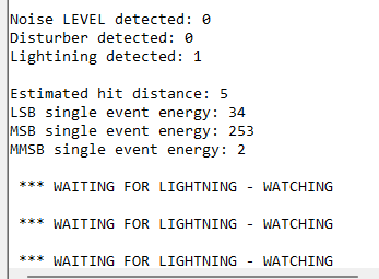
If the sensor detects lightning, then you will see the following results.
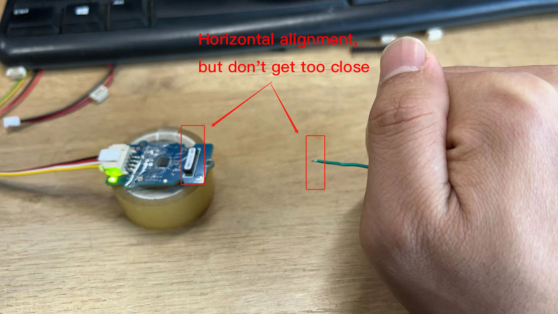
For testing purposes, you can use the lighter's igniter to simulate lightning to check if the sensor is working properly.
Resources
Tech Support & Product Discussion
Thank you for choosing our products! We are here to provide you with different support to ensure that your experience with our products is as smooth as possible. We offer several communication channels to cater to different preferences and needs.