Grove - Human Presence Sensor (AK9753)
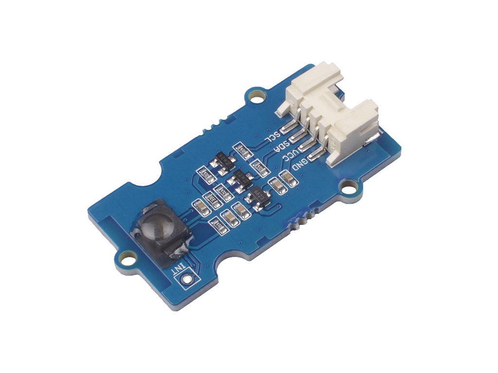
The Grove - Human Presence Sensor can be used to detect the presence of the human body or any other infrared objects. Moreover, it is composed of four quantum IR sensors and an integrated circuit (IC) for characteristic compensation, so it can be used to detect the motion of the IR object and the relative position where the IR object moves. An integral analog-to-digital converter provides 16-bits data outputs. This module is suitable for several feet human detector.
You can find a lot of infrared sensors on our website, this one will be one of the most interesting. With a certain algorithm, it can even achieve gesture recognition. We hope you enjoy it.

Feature
- Quantum-type IR Sensor with Four IR Elements
- 16-bits Digital Outputs to I2C bus
- Integrated temperature sensor
- Interrupt Function
- Low Current Consumption
Specification
| Item | Value |
|---|---|
| Operating Voltage | 3.3V / 5V |
| Operating Temperature | -30℃ ~ 85℃ |
| Human Presence Detect Range | < 3m |
| IR Output Resolution | 16 bit |
| Temperature Measurement Range | -10℃ ~ 60 ℃ |
| Interface | I2C |
| I2C Address | 0x64(default) 0x65 / 0x66(configurable) |
Typical applications
- Human body detect
- Proximity sensor
- Motion detect
Hardware Overview
Pin Out


Schemaitc
Power
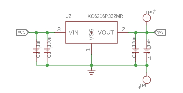
The AK9763 works with a low oprating voltage--1.71~3.63V, so we use the XC6206P332MR chip to provide a stable 3.3V. The input of XC6206P33 ranges from 1.8V to 6.0V, so you can use this module with your Arduino both in 3.3V and 5V.
Bi-directional level shifter circuit

This is a typical Bi-directional level shifter circuit to connect two different voltage section of an I2C bus. The I2C bus of this sensor use 3.3V, if the I2C bus of the Arduino use 5V, this circuit will be needed. In the schematic above, Q1 and Q2 are N-Channel MOSFET 2N7002A, which act as a bidirectional switch. In order to better understand this part, you can refer to the AN10441
Platforms Supported
| Arduino | Raspberry Pi | |||
|---|---|---|---|---|
The platforms mentioned above as supported is/are an indication of the module's software or theoritical compatibility. We only provide software library or code examples for Arduino platform in most cases. It is not possible to provide software library / demo code for all possible MCU platforms. Hence, users have to write their own software library.
Getting Started
Play With Arduino
Hardware
Materials required
| Seeeduino V4.2 | Base Shield | Grove - Human Presence Sensor (AK9753) |
|---|---|---|
 |  |  |
| Get One Now | Get One Now | Get One Now |
1 Please plug the USB cable gently, otherwise you may damage the port. Please use the USB cable with 4 wires inside, the 2 wires cable can't transfer data. If you are not sure about the wire you have, you can click here to buy
2 Each Grove module comes with a Grove cable when you buy. In case you lose the Grove cable, you can click here to buy.
Step 1. Connect the Grove - Human Presence Sensor (AK9753) to port I2C of Grove-Base Shield.
Step 2. Plug Grove - Base Shield into Seeeduino.
Step 3. Connect Seeeduino to PC via a USB cable.

If we don't have Grove Base Shield, We also can directly connect this module to Seeeduino as below.
| Seeeduino | Grove Cable | Grove - Human Presence Sensor (AK9753) |
|---|---|---|
| GND | Black | GND |
| 5V or 3.3V | Red | VCC |
| SDA | White | SDA |
| SCL | Yellow | SCL |
Software
If this is the first time you work with Arduino, we strongly recommend you to see Getting Started with Arduino before the start.
Step 1. Download the Grove_Human_Presence_Sensor Library from Github.
Step 2. Refer to How to install library to install library for Arduino.
Step 3. Now you can find four demo in the Arduino IDE by click File --> Examples --> Grove Human Presence Sensor Library

Example1-BasicReading: This example reads the raw (uint16_t) data of four IR sensors, and print these raw data in the serial.
Example2-PlotDiff: Read the raw data and plot in the serial plotter.
Example3-DetectPresence: Detect the presence of IR object.
Example4-PlotMovement: Detect the movement and plot in the serial plotter.
Or, find them on your computer in the folder C:XXXX\Arduino\libraries\Grove_Human_Presence_Sensor-master\examples, XXXX is the location you installed the Arduino IDE.

- Step 4. Choose one demo, upload the code. If you do not know how to upload the code, please check How to upload code.
Now let's check what will happen then:
Example1-BasicReading:
When you upload the example1 code, Open the Serial Monitor of Arduino IDE by click Tool-> Serial Monitor. Or tap the ++ctrl+shift+m++ key at the same time. Set the baud rate to 9600.
You can see the following results:
Grove - Human Presence Sensor example
1:[432], 2:[288], 3[248], 4:[384], temp[20.87], millis[109]
1:[424], 2:[296], 3[232], 4:[400], temp[20.87], millis[215]
1:[448], 2:[280], 3[224], 4:[360], temp[20.87], millis[319]
1:[424], 2:[280], 3[224], 4:[368], temp[20.87], millis[424]
1:[440], 2:[256], 3[248], 4:[376], temp[20.87], millis[530]
1:[440], 2:[280], 3[224], 4:[384], temp[20.75], millis[634]
1:[464], 2:[296], 3[216], 4:[392], temp[20.75], millis[740]
1:[416], 2:[288], 3[240], 4:[376], temp[20.75], millis[844]
1:[432], 2:[288], 3[216], 4:[392], temp[20.75], millis[950]
1:[440], 2:[296], 3[208], 4:[384], temp[20.75], millis[1055]
1:[424], 2:[248], 3[192], 4:[376], temp[20.75], millis[1160]
1:[432], 2:[264], 3[200], 4:[384], temp[20.75], millis[1265]
1:[440], 2:[248], 3[208], 4:[352], temp[20.75], millis[1371]
1:[400], 2:[256], 3[192], 4:[320], temp[20.75], millis[1475]
1:[368], 2:[208], 3[152], 4:[296], temp[20.75], millis[1581]
1:[608], 2:[384], 3[368], 4:[560], temp[20.75], millis[1686]
1:[1320], 2:[912], 3[736], 4:[960], temp[20.75], millis[1790]
1:[2168], 2:[1664], 3[1336], 4:[1752], temp[20.75], millis[1896]
1:[2544], 2:[2192], 3[2112], 4:[2376], temp[20.75], millis[2001]
1:[2536], 2:[2256], 3[2280], 4:[2520], temp[20.75], millis[2107]
1:[2144], 2:[2064], 3[2168], 4:[2328], temp[20.75], millis[2212]
The 1:[] means the measurement data of IR sensor1, 2:[] means the measurement data of IR sensor2, 3:[] means the measurement data of IR sensor3, 4:[] means the measurement data of IR sensor4. All of those for parameters value range from -32767 ~ 32767. This parameter reflects the intensity of the detected infrared light. The stronger the infrared intensity, the larger the parameter value.
The temp[] means the measurement data of Integrated temperature sensor, range from -10℃ to +60℃.
The millis[109] means the system time since this program started, offered by the Arduino.
Example2-PlotDiff
When you upload the example2 code, Open the Serial Plotter of Arduino IDE by click Tool-> Serial Plotter. Or tap the ++ctrl+shift+l++ key at the same time. Set the baud rate to 9600.
You can see the following results:

This example reads the data of four IR sensors and converts them into current (pA), then plot diff13 and diff24 into the Arduino IDE Serial Plotter.
diff13 = IR1 - IR3 // blue line
diff24 = IR2 - IR4 // red line
Example3-DetectPresence
When you upload the example1 code, Open the Serial Monitor of Arduino IDE by click Tool-> Serial Monitor. Or tap the ++ctrl+shift+m++ key at the same time. Set the baud rate to 9600.
You can see the following results:
Grove - Human Presence Sensor example
o o x o  millis: 16949
o x x o  millis: 17050
x x x x  millis: 17153
x x x x  millis: 17254
x x x x  millis: 17355
x x x x  millis: 17457
This example detects the presence of IR object. The detection is based on the derivative of the sensor value. If the derivative is greater than a threshold, we think that some IR object entered the view of the sensor. The derivative of each channel is calculated by the following formula:
$$ derivativeIR1= \Delta IR1 / \Delta t $$
$\Delta t$ represents the time interval and $\Delta IR1$ represents output value change of IR Sensor1 during the time interval.
In the output, O means no detection, X means detected. The order of the outputs corresponds to the physical location of the IR sensors.
e.g.
o o x o
Means the third IR sensor detected the IR object and the others did not(The IR object may come from the top). You can find the IR sensor physical location at Pin Out
Example4-PlotMovement
When you upload the example4 code, Open the Serial Plotter of Arduino IDE by click Tool-> Serial Plotter. Or tap the ++ctrl+shift+l++ key at the same time. Set the baud rate to 9600.
You can see the following results:

The detection is based on the derivative of the difference value of IR1_IR3 or IR2_IR4. The derivative of IR1_IR3 or IR2_IR4 is calculated by the following formula:
$$ derivativeIR1_IR3=\Delta (IR1-IR3)/\Delta t $$
The meaning of each curve in the figure is:: (in order)
- diff13 // IR1-IR3, blue line
- Movement in the direction 1-3 // derivativeIR1_IR3, red line
(a pulse, positive pulse mean from 1 to 3, otherwise from 3 to 1) - diff24 // IR2-IR4, green line
- Movement in the direction 2-4 // derivativeIR1_IR3, orange line
(a pulse, positive pulse mean from 2 to 4, otherwise from 4 to 2)
Schematic Online Viewer
Resources
[PDF] Datasheet AK9753
[PDF] XC6206 DATASHEET
Tech Support & Product Discussion
Thank you for choosing our products! We are here to provide you with different support to ensure that your experience with our products is as smooth as possible. We offer several communication channels to cater to different preferences and needs.