Grove - Triple Color E-Ink Display 1.54"

The Grove - Triple Color E-Ink Display 1.54'' is a screen that can still be displayed after power off, we call it E-Paper(electronic paper) or E-Ink. The display is a TFT active matrix electrophoretic display, with interface and a reference system design.The 1.54 inch active area contains 152x152 pixels, and has 1-bit white/black and 1-bit red full display capabilities.
Due to the advantages like ultra low power consumption, wide viewing angle, clear display without electricity, it is an ideal choice for applications such as shelf label, industrial instrument, and so on.

Feature
- High contrast
- High reflectance
- Ultra wide viewing angle
- Ultra low power consumption
- On-chip display RAM
##Specification
| Item | Value |
|---|---|
| Supply voltage | 3.3V / 5V |
| Operating temperature | 0~40℃ |
| Storage temperature | -25~60℃ |
| Humidity range | 40~70%RH |
| Display resolution | 152(H) x 152(V) pixel |
| DPI | 140 |
| Interface | UART |
| Baud rate with Arduino | 230400 |
Frequent continuous refresh will cause irreparable damage to E-Ink. It is recommended that the refresh interval be greater than 180s.
Pinout

Platforms Supported
| Arduino | Raspberry Pi |
|---|---|
|
|
Getting Started
Arduino Demo
Hardware
Materials required
| Seeeduino V4.2 | Base Shield | Grove - Triple Color E-Ink Display 1.54'' |
|---|---|---|
|
|
|
| Get ONE Now | Get ONE Now | Get ONE Now |


**1** Please plug the USB cable gently, otherwise you may damage the port. Please use the USB cable with 4 wires inside, the 2 wires cable can't transfer data. If you are not sure about the wire you have, you can click [here](https://www.seeedstudio.com/Micro-USB-Cable-48cm-p-1475.html) to buy

**2** Each Grove module comes with a Grove cable when you buy. In case you lose the Grove cable, you can click [here](https://www.seeedstudio.com/Grove-Universal-4-Pin-Buckled-20cm-Cable-%285-PCs-pack%29-p-936.html) to buy.
Step 1. Plug Grove - Base Shield into Seeeduino.
Step 2. Connect Seeeduino to PC via a USB cable.
Step 3. Download the code, please refer to the software part.
Step 4. Connect the Grove - Triple Color E-Ink Display 1.54'' to port UART of Grove-Base Shield.

  This module communicate with the control board via the UART interface. If you use the Atmega328p board like Arduino UNO or Seeeduino V4.2, you need to unplug this module before download the code, beacause there is only one hardware serial port.
  If this module occupied the UART port, the download program cannot use the serial port. However if you use SAMD board, like seeeduino Lotus, Arduino Mega, there are two or more hardware serial port available. So there is no need to unplug the module before download.
Software
If this is the first time you work with Arduino, we strongly recommend you to see [Getting Started with Arduino](https://wiki.seeedstudio.com/Getting_Started_with_Arduino/) before the start.
Step 1. Download the Demo code from Github.
Step 2. Open the E_ink154_factoryCode.ino file with your Arduino IDE.
Step 3. Upload the demo. If you do not know how to upload the code, please check How to upload code.
If everything goes well, you will see the display flickering, and the the display will show the seeed logo
DIY

It will be a lot fun to display your own image, now, let's show you how to DIY your own E-paper.
Before the start, please check the E_ink154_factoryCode.ino again. You can find the two array easily.
const unsigned char IMAGE_BLACK[] PROGMEM = { /* 0X00,0X01,0XC8,0X00,0XC8,0X00, */
0XFF,0XFF,0XFF,0XFF,0XFF,0XFF,0XFF,0XFF,0XFF,0XFF,0XFF,0XFF,0XFF,0XFF,0XFF,0XFF,
0XFF,0XFF,0XFF,0XFF,0XFF,0XFF,0XFF,0XFF,0XFF,0XFF,0XFF,0XFF,0XFF,0XFF,0XFF,0XFF,
0XFF,0XFF,0XFF,0XFF,0XFF,0XFF,0XFF,0XFF,0XFF,0XFF,0XFF,0XFF,0XFF,0XFF,0XFF,0XFF,
....
....
....
0XFF,0XFF,0XFF,0XFF,0XFF,0XFF,0XFF,0XFF,0XFF,0XFF,0XFF,0XFF,0XFF,0XFF,0XFF,0XFF,
0XFF,0XFF,0XFF,0XFF,0XFF,0XFF,0XFF,0XFF,0XFF,0XFF,0XFF,0XFF,0XFF,0XFF,0XFF,0XFF,
0XFF,0XFF,0XFF,0XFF,0XFF,0XFF,0XFF,0XFF,};
and
const unsigned char IMAGE_RED[] PROGMEM = { /* 0X00,0X01,0XC8,0X00,0XC8,0X00, */
0XFF,0XFF,0XFF,0XFF,0XFF,0XFF,0XFF,0XFF,0XFF,0XFF,0XFF,0XFF,0XFF,0XFF,0XFF,0XFF,
0XFF,0XFF,0XFF,0XFF,0XFF,0XFF,0XFF,0XFF,0XFF,0XFF,0XFF,0XFF,0XFF,0XFF,0XFF,0XFF,
0XFF,0XFF,0XFF,0XFF,0XFF,0XFF,0XFF,0XFF,0XFF,0XFF,0XFF,0XFF,0XFF,0XFF,0XFF,0XFF,
0XFF,0XFF,0XFF,0XFF,0XFF,0XFF,0XFF,0XFF,0XFF,0XFF,0XFF,0XFF,0XFF,0XFF,0XFF,0XFF,
....
....
....
0XFF,0XFF,0XFF,0XFF,0XFF,0XFF,0XFF,0XFF,0XFF,0XFF,0XFF,0XFF,0XFF,0XFF,0XFF,0XFF,
0XFF,0XFF,0XFF,0XFF,0XFF,0XFF,0XFF,0XFF,0XFF,0XFF,0XFF,0XFF,0XFF,0XFF,0XFF,0XFF,
0XFF,0XFF,0XFF,0XFF,0XFF,0XFF,0XFF,0XFF,};
As you can see, the two array is called const unsigned char IMAGE_BLACK[] and const unsigned char IMAGE_RED[],
const unsigned char IMAGE_BLACK[] is used for black image display
const unsigned char IMAGE_RED[] is used for red image display
Actually, to display your own image, you just need to replace those two image array. That is to say, you just need to get your own image array. Luckily, there is a tool Image2LCD, you can google it, it's not difficult to find. Suppose you have downloaded and installed this software. Next, we will show you how to use this software.
- Step 1. Prepare a picture of 152*152 pixels.
The ink screen only supports pictures with gray level of second-order, that is, black and white. If the gray level of the picture is too much, the whole color cannot be completely displayed.
- Step 2. Open the Image2LCD software and click the Open icon to open your picture. You will see the fallowing window.

Please check the corresponding option as shown above.
- Output file type -> *.C
- Scan mode -> Horizon Scan
- BitsPixel -> monochrome
- Max Width and Height -> 152 x 152
- Reverse color: Whether you need to check this option is based on the effect you need to display. For more detail please check the Table 1 below.
- Step 3. After you configure the above options, you only need to click the Save button in the upper left corner to generate the corresponding image array. Then replace the the factoryCode array with your own image array.
As we mentioned above, there are two arrays, you may be cofused: which one to replace? Well, it depends on what display effect do you want. Check the Table 1.
| Display | Black background Red image | White background Red image | Red background Black image | Red background White image |
|---|---|---|---|---|
| Black Array | 00 | FF | 00 | FF |
| Red Array | Image(Reversed) | Image(Reversed) | Image | Image |
| Display | Full screen red | White background Black image | Red background red | Black background White image |
|---|---|---|---|---|
| Black Array | Image(Reversed) | Image(Reversed) | Image | Image |
| Red Array | 00 | FF | 00 | FF |
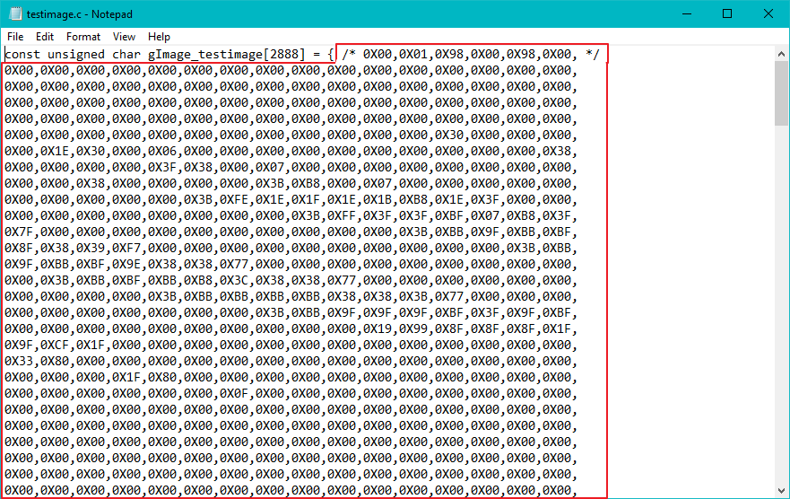
    a.**00** means all elements in the array are 0x00, actually you need 2888 0x00
    b.**FF** means all elements in the array are 0xFF, actually you need 2888 0xFF
    c.**Image(Reversed)** means you need to check the **Reverse color** option in the **Step 2(Figure 4)**
    b.**Image** means do not check the **Reverse color** option in the **Step 2(Figure 4)**
    *Make a 2888 0x00 or 0xFF array?*
    *Don't worry, we feel you pain, you can just click the 0x00.c and 0xFF.c file and copy into your code.*
We consider the original state is full screen white. When updating the image, the black array is updated first, then the red array is updated, and the image of the red array overwrites the black image.
This display is 152 x 152, so there are 152x152=23104 pixels, each pixel is controled by one bit. The element in the array is a two-digit hexadecimal number, like 0xF0. Convert 0xF0 to a binary number we will get 1111 0000. A pixel with a value of 1 will display white, and a pixel with a value of 0 will display the color of the corresponding array (red or black). Which means each element in the image array controls 8 pixels. So you need an array of 23104/8=2888 elements.
Step 4. Download the code into your arduino, then you plug the display module into the arduino board. After blinking for a while, you will see the pattern you set.
Schematic Online Viewer
Resources
Tech Support & Product Discussion
Thank you for choosing our products! We are here to provide you with different support to ensure that your experience with our products is as smooth as possible. We offer several communication channels to cater to different preferences and needs.