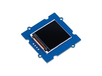
Grove 1.2-inch IPS Display

The Grove-1.2 Inch IPS Display is a meticulously crafted 1.2-inch serial liquid crystal display brought to you by Seeed Studio. Offering a superior resolution of 240x240, this display provides crystal clear, colorful image representation. The design rationale behind this display is to present a simple, high-quality display solution to meet the needs of various DIY or Internet of Things (IoT) projects.
It adopts a serial SPI interface and only requires SCK and SDA for connection to the main controller. This simplifies the user's operations and saves wiring time. The RGB color display further enhances each image with rich and vibrant colors.
Simultaneously, the Grove-1.2 Inch IPS Display employs IPS full-view angle technology. Regardless of the angle from which users view, they can get almost the same visual experience. This means your project will present the best display effect from every angle.
Moreover, we have chosen ST7789 as the driver IC for the display and have prepared an open-source driver library and example code for your convenience. This will enable you to get started quickly with your project development.
Features
- Simplified Interface: The display adopts a serial SPI interface and only requires the SCK and SDA connections to the main controller. This greatly simplifies user operation and saves time on wiring.
- High Resolution: With a high-resolution of 240x240 pixels, the display can provide clear and vibrant images, improving the visual experience of your project.
- Full-view IPS Technology: The Grove-1.2 Inch IPS Display uses In-Plane-Switching (IPS) technology, which offers consistent, accurate color from all viewing angles.
- Rich Color: The display can show up to 65k colors. The RGB color display adds depth and variation to the images, making them more vibrant and lifelike.
- Compact Size: The screen size is 24.76x26.8mm, and the circuit board size is 40x40mm. Its compact size makes it a perfect fit for various DIY or IoT projects.
- Wide Input Voltage Range: The circuit board can accept an input voltage of 3.3V or 5V, offering compatibility with a wide range of power sources.
- Reliable Driver IC: The display uses ST7789 as its driver IC. Its open-source driver library and example code make it easier for users to get started.
- Wide Operating Temperature: The working temperature range of -20 to 70 degrees Celsius makes this display suitable for various environments.
Application Ideas
- DIY Weather Station: The Grove-1.2 Inch IPS Display can be used in a home-made weather station to provide real-time weather information. It can display rich and vibrant icons and data, providing an engaging user experience.
- Personal Digital Art Display: The display can be incorporated into a digital art device, where it can showcase your creative ideas with its high-resolution and colorful display. This makes it an excellent component for art or design projects.
- DIY Gaming Console: Given its high-resolution and full-view display, the Grove-1.2 Inch IPS Display is an excellent choice for homemade gaming consoles. Its vibrant color display will enhance the gaming experience.
- Smart Home Systems: The display can be integrated into smart home systems, providing clear and vibrant visual feedback of various home conditions or system status.
- Educational Projects: In the educational sector, the display can be used in classroom projects to teach students about graphics, coding, and electronics. Its simple interface and easy setup make it ideal for learning environments.
- Industrial Control Panels: In industrial applications, the display can be used in control panels to display important information or statuses, helping operators monitor and control industrial processes. Its wide viewing angle ensures clear visibility from various perspectives.
Hardware Overview
Pin Map

Getting Started
If this is the first time you work with Arduino, we strongly recommend you to see Getting Started with Arduino before the start.
Play With Arduino
Hardware
Materials required
| Seeeduino V4.2 | Base Shield | Grove-1.2 Inch IPS Display |
|---|---|---|
|
|
|
| Get One Now | Get One Now | Get One Now |


1 Please plug the USB cable gently, otherwise you may damage the port. Please use the USB cable with 4 wires inside, the 2 wires cable can't transfer data. If you are not sure about the wire you have, you can click here to buy
2 Each Grove module comes with a Grove cable when you buy. In case you lose the Grove cable, you can click here to buy.
-
Step 1. Connect Grove-1.2 Inch IPS Display to D7(D7/D8) port of Grove-Base Shield.
-
Step 2. Plug Grove - Base Shield into Seeeduino.
-
Step 3. Connect Seeeduino to PC via a USB cable.

If we don't have Grove Base Shield, We also can directly connect Grove-1.2 Inch IPS Display to Seeeduino as below.
| Seeeduino | Grove-1.2 Inch IPS Display |
|---|---|
| 5V | Red (VCC) |
| GND | Black (GND) |
| SDA | White (DTA) |
| SCK | Yellow (SCK) |
Software
- Step 1. Download the Arduino Library from Github.
-
Step 2. Refer to How to install library to install library for Arduino.
-
Step 3. After downloading and installing the library correctly, you can find an example program named ST7789_HelloWorld.ino in the examples folder. This program is designed for the Grove-1.2 Inch IPS Display.
#include <Adafruit_GFX.h>
#include <Arduino_ST7789_Fast.h>

#define SCK   7
#define SDA   8

Arduino_ST7789 lcd = Arduino_ST7789(SCK, SDA);

void setup(void)
{
    lcd.init();
    lcd.fillScreen(BLACK);

    lcd.setCursor(0, 0);
    lcd.setTextColor(RED,BLACK);
    lcd.setTextSize(3);
    lcd.println("HELLO WORLD");
}

void loop()
{

}
- Step 4. You will find Hello World printed on the display.

Fast IO with Arduino UNO
Operating Arduino's I/O pins directly through registers can provide higher efficiency and speed, as opposed to using the standard digitalWrite() function. However, this method generally requires a more in-depth understanding of Arduino hardware and the workings of microcontrollers.
If you wish to utilize faster I/O, you'll need to make some modifications in the Arduino_ST7789_Fast.h file. Firstly, you should change line 20 to: #define FAST_IO 1. Additionally, between lines 23 and 26, write the code to set the IO high and low. Below is an example of using D7/D8:
#define FAST_IO 1

#if FAST_IO
#define LCD_SCK_SET PORTD |= (1 << PORTD7); // SET SCK HIGH
#define LCD_SDA_SET PORTB |= (1 << PORTB0); // SET SDA HIGH
#define LCD_SCK_CLR PORTD &= ~(1 << PORTD7); // SET SCK LOW
#define LCD_SDA_CLR PORTB &= ~(1 << PORTB0); // SET SDA LOW
#endif
Below is a brief tutorial on how to use registers to control I/O pins on Arduino UNO:
Arduino UNO has three ports, labeled as B, C, and D. Each port has a corresponding data register, which are PORTB, PORTC, and PORTD. These registers can be used to directly control I/O pins.
For instance, if you want to set digital pin 13 (corresponding to the 5th bit of PORTB, or PORTB5) to HIGH, you can write as follows:
PORTB |= (1 << 5);
This statement sets the 5th bit of PORTB to 1 without changing other bits. This is achieved via the bitwise OR operator (|=) and the left-shift operator (<<).
Likewise, if you want to set digital pin 13 to LOW, you can write as follows:
PORTB &= ~(1 << 5);
This statement sets the 5th bit of PORTB to 0 without changing other bits. This is achieved via the bitwise AND operator (&=) and the bitwise NOT operator (~).
The following shows all the ports on Arduino UNO and their corresponding registers:
Digital Ports
- Digital ports 0 - 7 correspond to register PORTD, bits PORTD0 to PORTD7
- Digital ports 8 - 13 correspond to register PORTB, bits PORTB0 to PORTB5
** Analog Input Ports **
- Analog input ports A0 - A5 correspond to register PORTC, bits PORTC0 to PORTC5
Analog input ports can also function as digital I/O, corresponding to digital pin numbers 14 to 19. For instance, A0 can also serve as digital pin 14.
Each I/O register also has two related registers to control the mode (input or output) of the pins and the pull-up resistors of input pins. For instance, the control registers for PORTD are DDRD and PIND. The DDRx register is used to set the pin mode, and the PINx register is used to read the pin state.
Before writing to the PORTx register, you should first ensure that the corresponding DDRx register is set correctly. For example, if you want to set PD0 as output and output HIGH, you should set the DDRD register first:
DDRD |= (1 << 0);  // Set PD0 as output
PORTD |= (1 << 0);  // Output HIGH to PD0
This information can be found in the datasheet of ATmega328P, which is the microcontroller of Arduino UNO. If you are using another Arduino model, you may need to refer to the datasheet of the respective microcontroller as different microcontrollers may have different port and register layouts.
When manipulating registers, it is essential to exercise caution, as any erroneous operation may impact the status of other pins or even the function of the microcontroller.
Users who want to use the register operation mode of this product need to understand and implement the above knowledge and skills independently.
FAQ
1. The screen does not work when I reprogram it while the screen is connected
A: If your program is constantly communicating with the screen, reprogramming can interrupt this process, causing the screen to malfunction. You can try turning off the power to restore normal screen operation.
3. What kind of power supply should I use for the display?
A: The circuit board can accept an input voltage of 3.3V or 5V, so you can use a power supply within this range.
4. Can I use the display under extreme temperature conditions?
A: The display has a working temperature range of -20 to 70 degrees Celsius. However, for optimal performance and longevity, it's recommended to operate the display within normal room temperature conditions.
5. The colors on my display do not look right. What could be the problem?
A: Please ensure the display is correctly initialized in your code and you're using the correct color values. If you're still facing issues, there may be a problem with the display or the connecting wires. Please check the connections or try with another display if available.
Schematic Online Viewer
Resources
- [ZIP] Eagle File for Grove-1.2 Inch IPS Display
- [PDF] ST7789 Spec
Tech Support & Product Discussion
Thank you for choosing our products! We are here to provide you with different support to ensure that your experience with our products is as smooth as possible. We offer several communication channels to cater to different preferences and needs.