Wio Extension RTC (Real Time Clock)

The Wio Extension - RTC is an extension board for Wio LTE, it can provide the Real-Time Clock function via the I2C port. This board is based on NXP PCF8523 chip, which can provide year, month, day, weekday, hours, minutes, and seconds information.
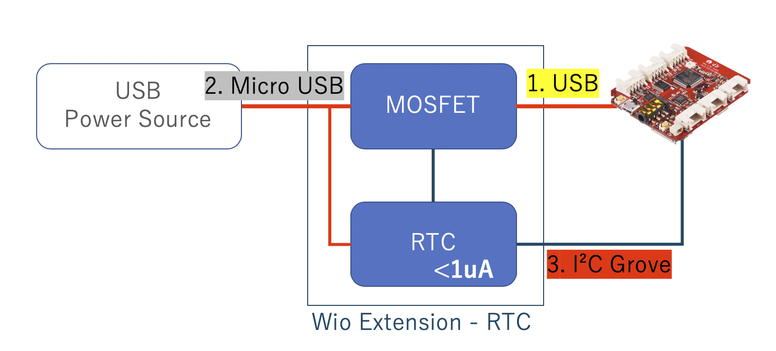
This board is powered by Micro-USB port, communicate with the Wio LTE via I2C port, and we also provide a USB power output which can be turned off/on by a on-board switch, so that you can use the Wio Extension - RTC board to power the Wio LTE. When the power supply to Wio boards ( Like the following picture), the standby current of whole system is less than 1 uA.

Feature
- Extensibility
- Able to supply Wio boards with 3.3 voltage.
Hardware Overview

Platforms Supported
| Arduino | Raspberry Pi | |||
|---|---|---|---|---|
Getting Started
Play With Arduino
Materials required
| Wio LTE Boards | Wio-Extension-RTC | Grove - Buzzer | Grove - Red LED |
|---|---|---|---|
 | | 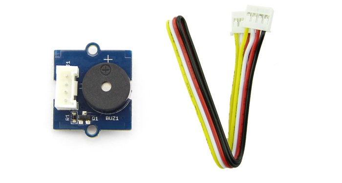 |  |
| Get ONE Now | Get ONE Now | Get ONE Now | Get ONE Now |
Since Wio Extension - RTC just controlling USB power supply set from I2C, you can use this board to manage the power supply almost for every MCU boards powering from USB.
1 Please plug the USB cable gently, otherwise you may damage the port. Please use the USB cable with 4 wires inside, the 2 wires cable can't transfer data. If you are not sure about the wire you have, you can click here to buy
2 Each Grove module comes with a Grove cable when you buy. In case you lose the Grove cable, you can click here to buy.
Hardware
-
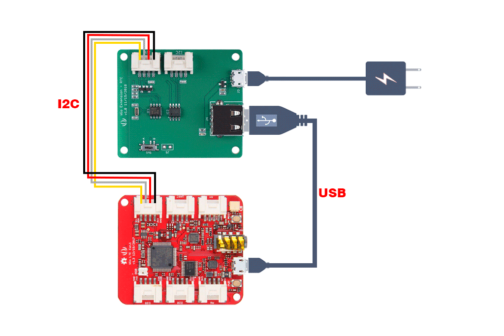
Step 1. Connect the Wio-Extension-RTC to the I2C port of the Wio LTE Boards.
-
Step 2. Connect Wio LTE Boards.to PC via a USB cable.
-
Step 3. Connect Grove - Buzzer or Grove - Red LED to D38 of Wio LTE.
Software
If this is the first time you work with Arduino, we strongly recommend you to see Getting Started with Arduino before the start.The driver of this board is rely on the head file of Seeed STM32F4 Board(JP mirror) by Seeed K.K. , so whether you have installed your wio board with the tutorial of Getting Started with Arduino, you need to do the following step.
Step 1 Install library
Open your Arudino IDE, click on File > Preferences, and copy below url to Additional Boards Manager URLs.
http://www.seeed.co.jp/package_SeeedJP_index.json

Click on Toos > Board > Board Manager, and enter Wio to the text box.

Click Seeed STM32F4 Board(JP mirror) by Seeed K.K. then an Install button appear, click on it to finish the step, this process takes about 5 minutes to half an hour, which depend on the speed of your network.
Click on Tools > Manage Libraries, and enter Wio to the text box.
 Click
Click Wio LTE for Arduino by Seeed K.K. then an Install button appear, click on it to finish the step.
Unzip the sample sketch, and open wiortc-sample.ino with Arduino IDE.
Step2 Download the code
-
Press and hold BOOT button at back side of the Wio LTE and plug the USB to PC.
-
We will see STM BOOTLARDER in device manager.
-
Select Tools→Boards→Wio_Tracker_LTE.

-
Select Sketch→Upload to upload the code to Wio_LTE.
-
Press RST button to enable the COM port. Tips
When you download most Arduino bords, you need to choose a right COM port, but for this board, you must keep the COM configuration to be blank.

- Use Serial monitor to print the serial message.
#include <WioLTEforArduino.h>
#include "WioRTC.h"

////////////////////////////////////////////////////////////////////////////////
// Defines

#define BOOT_INTERVAL   (30)  // [sec.]

////////////////////////////////////////////////////////////////////////////////
// Global variables

WioLTE Wio;
WioRTC Rtc;

////////////////////////////////////////////////////////////////////////////////
// setup and loop

void setup()
{
  delay(200);

  SerialUSB.begin(115200);
  SerialUSB.println("");
  SerialUSB.println("--- START ---------------------------------------------------");

  ////////////////////////////////////////
  // Low-level initialize

  SerialUSB.println("### I/O Initialize.");
  Wio.Init();

  SerialUSB.println("### Power supply ON.");
  Wio.PowerSupplyGrove(true);
  delay(500);

  ////////////////////////////////////////
  // Device initialize

  SerialUSB.println("### Device initialize.");
  Wire.begin();
  Rtc.begin();

  ////////////////////////////////////////
  // Completed

  SerialUSB.println("### Completed.");
}

void loop()
{
  uint8_t val;
  Rtc.EepromRead(0, &val, sizeof(val));
  SerialUSB.print("EEPROM value is ");
  SerialUSB.println(val);

  val++;
  Rtc.EepromWrite(0, &val, sizeof(val));

  SerialUSB.println("Beep.");
  pinMode(WIO_D38, OUTPUT);
  digitalWrite(WIO_D38, HIGH);
  delay(200);
  digitalWrite(WIO_D38, LOW);

  SerialUSB.println("Shutdown.");
  Rtc.SetWakeupPeriod(BOOT_INTERVAL);
  Rtc.Shutdown();
  while (1) {}
}
Schematic Online Viewer
Resources
- [ZIP] Wio-Extension-RTC
- [Sample] Wio-Extension-RTC Sample Code
Tech Support & Product Discussion
if you have any technical issue. submit the issue into our forum. Thank you for choosing our products! We are here to provide you with different support to ensure that your experience with our products is as smooth as possible. We offer several communication channels to cater to different preferences and needs.