MT3620 Mini Dev Board

MT3620 Mini Dev Board is a lite version of Seeed previous Azure Sphere MT3620 Development Kit. For an introduction to Azure sphere, please refer to this link Azure Sphere.
We developed this board to meet the needs of developers who need smaller sizes, are more scalable, and have lower costs. This development board is based on the MT3620 module, which greatly simplifies the difficulty of hardware design. The MT3620 module is developed by our partner AI-Link. Developers can easily reuse this design into their own projects. The development board uses two single-row pin headers for easy plug-in on other motherboards or expansion boards. Unlike the full-featured Azure Sphere MT3620 Development Kit, this development board optimizes the design by reducing some system hardware peripheral resources, and only provides the necessary hardware resources to developers. In terms of hardware specifications, we only support 2.4G Wi-Fi and reduce I2S and some GPIO ports.
What’s new of the MT3620 Mini Dev Board?
- Based on MT3620 module (WF-M620-RSA1)
- Reduce the board size from 50mm80mm16mm to 34mm60mm19mm
- Keep the necessary LED indicator and buttons
- The board form factor is more easier for add-on usage
The figure shows the full-feature dev board and new mini dev board size comparison:

The Azure Sphere operating system is pre-installed on the MT3620 and is designed to work with the Azure Sphere Security Service to create a secured IoT platform. Together the Azure Sphere OS and security service deliver:
- certificate-based device authentication to any web service
- software attestation and secure boot
- threat detection via failure reporting
- ongoing security updates
- an integrated, secured end-to-end IoT solution
MT3620 software development is supported using the powerful Microsoft Visual Studio IDE: Install Visual Studio and the Azure Sphere extension, plug the development board into a PC over USB, and start developing IoT applications with unprecedented levels of security.

-
Return policy: This product can only be activated once. Seeed will not accept return once the package has been opened. Check Warranty & Returns here. If there are any quality issues after opening the package, please contact Seeed Support Team [email protected].
-
Open Source Licenses: The software included in this product contains copyrighted software that is licensed under the GPL, LGPL or other open source licenses, listed ataka.ms/AzureSphereSDK. You may obtain the source code for applicable software from aka.ms/AzureSphereSDK or by sending an email to [email protected].
Features
- Azure Sphere: End-to-end security for IoT devices.
- Wi-Fi 802.11 b/g/n.
- Tri-core microcontroller with on-chip RAM & flash.
- Microsoft Visual Studio development environment.
- Online authentication & updates for device lifetime.
- Expand UART, I2C, SPI, ADC, GPIO resource on pin header.
Specification
Hardware
| Description | Value |
|---|---|
| MCU (using MT3620 module) | 1 *ARM Cortex A7 core @500MHz , 4MB RAM |
| 2* ARM Cortex M4 core @200MHz , 64KB RAM | |
| ISU | ISU 0 configured as SPI0 or UART0 or I2C0, ISU 1 configured as SPI1 or UART1 or I2C1 |
| - I2C runs at up to 1MHz | |
| - SPI runs at up to 40MHz | |
| - UART runs at up to 3Mbps | |
| Connectivity | 802.11 b/g/n Wi-Fi |
| ADC | 3 *12-bit ADC input I/O |
| RTC | 1* RTC with CR1220 3V battery holder |
| USB | 1 *Micro USB port for power supply and debugging, 5V/1A |
| LED | 1* RED LED -> Power |
| 1 *GREEN LED -> FTDI status | |
| 1* GREEN LED -> user controlled (can be configured as Wi-Fi status or other usage) | |
| Button | 1*Reset Button |
| Operating Temperature | -40~85°C |
| Dimensions | L:34mmW:60mmH:19mm |
| Certification | CE / FCC / MIC / RoHS |
Software
| IDE | Visual Studio |
| System | Windows10 |
| Programming Language | C |
Sopports
It is now possible to program all of the followings if building a real-time app.
- I2C
- 2xARM Cortex-M4 with FPU
- ADC
- PWM
- I2S (please refer to M4 with FPU)
If building a high-level OS app,it is possible to use ADC and PWM.
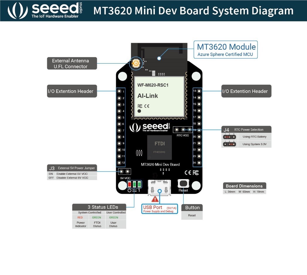
Hardware Overview
Board Diagram
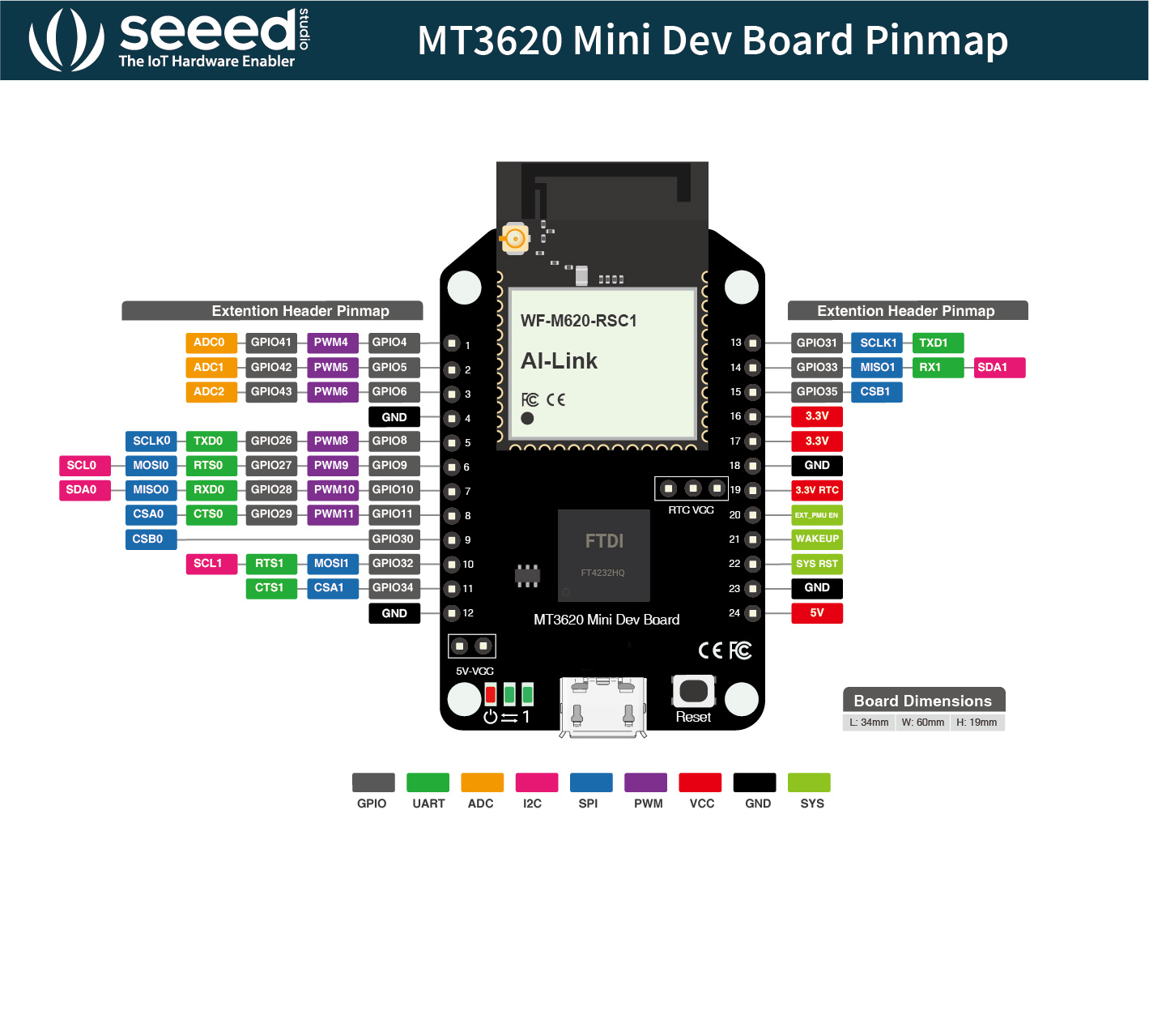
Board Pinmap
Applications
- Home/Building/Facilities
- Automation
- Security
- Equipment Management
- Utilities
- Public Safety
To understand how Azure Sphere works in a real-world setting, consider Contoso, Ltds cenario.
Install Azure Sphere
If you have MT3620 Mini Dev Board that has not yet been used, complete these steps first to get up and running.
MT3620 Mini Dev Board Demos
We build there demoes which combine MT3620 Mini Dev Board and Seeed Grove system.
Demo#1: MT3620 Mini Dev Board performs as an MCU, which connects with Grove-Button and USB to TTL adapter. Then you connect MT3620 Mini Dev Board and the USB to TTL adapter to PC usb ports. After you downloading the code, press Grove-Button and enter "Hello World!" from USB to TTL adapter, you can receive "Hello World!" from Visual Studio Output window.
Demo#2: MT3620 Mini Dev Board performs as an MCU, which connects with Grove-Light Sensor and USB to Grove-Rotary Sensor. Then you connect MT3620 Mini Dev Board to PC usb ports. After you downloading the code, you move your hand on top of the Grove-Light Sensor or rotate the Grove-Rotary Sensor, you can see analog outputs for both sensors from Visual Studio Output window.
Demo#3: MT3620 Mini Dev Board performs as an MCU, which connects with Grove - OLED Display 1.12". Then you connect MT3620 Mini Dev Board to PC usb ports. After you downloading the code, you press Grove-Button and enter "Hello World!" from USB to TTL adapter, you can receive "Hello World!" from Visual Studio Output window.
MT3620 Grove Breakout:MT3620 Mini Dev Board supports SPI, UART, I2C, Digital functions, but does not support the ADC function. So the MT3620 Grove Breakout includes AD7992 chip, which is a 12-bit, low power, successive approximation ADC with an I2C-compatible interface. Then connect to I2C interface of MT3620 Mini Dev Board.

Demo#1 Digital and UART
Part List
| MT3620 Mini Dev Board | MT3620 Grove Breakout | Grove - Button | USB To Uart 5V&3V3 |
|---|---|---|---|
 |  |  |  |
| Get One Now | Get One Now | Get One Now | Get One Now |
Hardware Connection

- Step 1. Connect Grove-Button to D1 of MT3620 Grove Breakout.
- Step 2. Connect USB To Uart adapter to UART0 of MT3620 Grove Breakout through Grove-Cable.
- Step 3. Plug MT3620 Grove Breakout to MT3620 Mini Dev Board.
- Step 4. Connect MT3620 Mini Dev Board and the USB to TTL adapter to PC usb ports.
Please make sure the voltage switch on USB to TTL adapter is turned to 5v. You connect the RX of the USB to ttl adapter to TX of MT3620 Grove Breakout, the TX of the USB to ttl adapter to RX of MT3620 Grove Breakout and GND as well. Do not connect the 5V.
Software
- Step 1. Download Azure Sphere Demo
- Step 2. Open the Samples\UART0 under Azure_Sphere_Demo
- Step 3. Double click UART0.sln
- Step 4. Right-Click the project name of your application, select Properties > C/C++ > General > Additional Include Directories
- Step 5. Click the down arraw > Edit... > New Line icons, modify the path of UART0, click Select Folder > OK > OK
- Step 6. Go to the application project Right-Click References > Add References, select Projets, click the check box of UART0, then click OK
- Step 7. Right-Click the project name of your application, select General > Target API Set, click the check box and set as 1+Beta1902 if you use the Visual Studio Community version and please skip this step if you use the Enterprise version.
- Step 8. Click the Remote GDB Debugger.
- Step 9. Open the COM monitor tool and select USB to TTL adapter serial port
- Step 10, Press the Grove-Button and send "Hello World!" from COM monitor tool.
- Step 11, You can see the below message from Visual Studio output window.
UART received 12 bytes: 'Hello World!'.
UART received 2 bytes: '
'.
UART received 12 bytes: 'Hello World!'.
UART received 2 bytes: '
'.
UART received 12 bytes: 'Hello World!'.
UART received 2 bytes: '
Demo#2 Analog
Part List
| MT3620 Mini Dev Board | MT3620 Grove Breakout | Grove-Light Sensor | Grove - Rotary Angle Sensor |
|---|---|---|---|
| |  |  |
| Get One Now | Get One Now | Get One Now | Get One Now |
Hardware Connection

- Step 1. Connect Grove-Rotary Angle Sensor to A0 of MT3620 Grove Breakout.
- Step 2. Connect Grove-Light Sensor to A1 of MT3620 Grove Breakout.
- Step 3. Plug MT3620 Grove Breakout to MT3620 Mini Dev Board.
- Step 4. Connect MT3620 Mini Dev Board to PC usb port.
Software
- Step 1. Download Azure Sphere Demo
- Step 2. Open the Samples\AD7991_I2C under Azure_Sphere_Demo
- Step 3. Double click AD7991_I2C.sln
- Step 4. Right-Click the project name of your application, select Properties > C/C++ > General > Additional Include Directories
- Step 5. Click the down arraw > Edit... > New Line icons, modify the path of AD7991_I2C, click Select Folder > OK > OK
- Step 6. Go to the application project Right-Click References > Add References, select Projets, click the check box of AD7991_I2C, then click OK
- Step 7. Right-Click the project name of your application, select General > Target API Set, click the check box and set as 1+Beta1902 if you use the Visual Studio Community version and please skip this step if you use the Enterprise version.
- Step 8. Click the Remote GDB Debugger, you move your hand on top of the Grove-Light Sensor or rotate the Grove-Rotary Angle Sensor, you can see analog outputs for both sensors from Visual Studio Output window.
A0: 192 A1: 2646
A0: 162 A1: 2644
A0: 1489 A1: 2647
A0: 621 A1: 2644
A0: 227 A1: 2648
A0: 33 A1: 2644
A0: 0 A1: 2647
A0: 0 A1: 2647
A0: 0 A1: 2647
A0: 0 A1: 2644
A0: 373 A1: 2643
A0: 885 A1: 2646
A0: 1717 A1: 2647
A0: 2057 A1: 2647
Demo#3 I2C
Part List
| MT3620 Mini Dev Board | MT3620 Grove Breakout | Grove-OLED Display 1.12'' V2 |
|---|---|---|
| |  |
| Get One Now | Get One Now | Get One Now |
Hardware Connection

- Step 1. Connect Grove-OLED Display 1.12'' V2 to I2C of MT3620 Grove Breakout.
- Step 2. Plug MT3620 Grove Breakout to MT3620 Mini Dev Board.
- Step 3. Connect MT3620 Mini Dev Board to PC usb port.
Software
- Step 1. Download Azure Sphere Demo
- Step 2. Open the Samples\SeeedOLED_I2C under Azure_Sphere_Demo
- Step 3. Double click SeeedOLED_I2C.sln
- Step 4. Right-Click the project name of your application, select Properties > C/C++ > General > Additional Include Directories
- Step 5. Click the down arraw > Edit... > New Line icons, modify the path of SeeedOLED_I2C, click Select Folder > OK > OK
- Step 6. Go to the application project Right-Click References > Add References, select Projets, click the check box of SeeedOLED_I2C, then click OK
- Step 7. Right-Click the project name of your application, select General > Target API Set, click the check box and set as 1+Beta1902 if you use the Visual Studio Community version and please skip this step if you use the Enterprise version.
- Step 8. Click the Remote GDB Debugger, you will see the info display on oled.
Remote debugging from host 192.168.35.1
Seeed oled 96*96 demo.
Door Remote Control Project
This is the Azure Sphere Secure Lock Demo. We build this Box with the new MT3620 Mini Dev Board and its Grove Breakout board. The MT3620 works as a device micro-controller and provides secure access to the cloud.

1. Let's find out how the hardware works:
On top of the box , there is a warning light ,which will flash when the door is open. The MT3620 reads the micro switch status and knows the door is open or not. The door is locked by an electromagnet switch. There are two relays, they are both driven by MT3620‘s GPIOs. One relay controls the electromagnet power source, by opening the relay, the electromagnet will be opened. The other relay controls the warning light.


2. MT3620 Mini Dev Board
- Step 1. Download Azure Sphere Demo.
- Step 2. Follow Quickstarts for Azure Sphere to open the Azure_Sphere_Demo\Demostrations\RemoteControlDoor\RemoteControlDoor.sln project.
- Step 3. Open the main.c under Source Files.
- Step 4. Modify wifiSsid and wifiPsk @line28 and 29.
- Step 5. Connect the demo to Azure IoT.
- Step 6. Click Build -> Rebuild Solution directly to the device.
- Step 7. Use the Remote Debug Tool to access the device.
- Step 8. Follow the video to operate the example in 3 different ways.
Resource
- [Product] Welcome to Azure Sphere
- [Library] Azure Sphere Demo Library
- [PDF] MT3620 Mini Dev Board Schematic
- [DataSheet] MediaTek MT3620 Product Brief
- [DataSheet] WF-M620 RSC1 datasheet
- [FAQ Web] Azure Sphere Forum
- [FAQ Web] Azure Sphere Github issues
Tech Support & Product Discussion
Thank you for choosing our products! We are here to provide you with different support to ensure that your experience with our products is as smooth as possible. We offer several communication channels to cater to different preferences and needs.